Aluminum Surface Finishing Corrosion Causes and Troubleshooting
In this paper, a review of several process solutions, examining coolants, solvent cleaning, alkaline clean/etch and deoxidizing/desmutting, listing intended and unintended chemical reactions along with possible mechanisms that would favor corrosion formation.
by W. John Fullen, Boeing Research and Technology & Jennifer Deheck, Boeing, Seattle, Washington, USA
Editor’s Note: This paper is a peer-reviewed and edited version of a presentation delivered at NASF SUR/FIN 2014 in Cleveland, Ohio on June 10, 2014. A printable PDF version is available by clicking HERE.
ABSTRACT
Aluminum corrosion is commonly encountered when performing chemical process operations involving surface finishing, predominantly in preparation for paint application. The protective oxide film of aluminum is only stable in a pH range of 4.5 -8.5. However, many process solutions intentionally exceed this pH range for the purpose of cleaning, metal removal and subsequent smut removal. These process solutions are formulated so as not to cause deleterious pitting or preferential etching. However, the susceptibility of aluminum to pitting depends on many extraneous factors, such as chloride ion concentration, pH control and initial surface condition. Electrochemical measurements via potentiodynamic scans have been shown to be an effective tool in analyzing the propensity of certain process solutions to contribute to observed pitting conditions. In this paper, a review of several process solutions, examining coolants, solvent cleaning, alkaline clean/etch and deoxidizing/desmutting, listing intended and unintended chemical reactions along with possible mechanisms that would favor corrosion formation. Further explanation is provided for the role of incoming water that is used for process solution make-up and the myriad of rinse tanks. Recommendations are provided for electrolytic processes that might be prone to stray currents affecting auxiliary equipment and thereby introducing deleterious contaminants into process solutions as a result of the corrosion products of compromised piping, fittings and fasteners from heating and cooling units. Strict adherence to process specification controls, regular monitoring of suspect contaminants, sound housekeeping and part handling best practices can alleviate many aluminum part processing corrosion occurrences.
Keywords: aluminum, aluminum surface finishing, corrosion causes, corrosion troubleshooting
Introduction
A protective oxide film of aluminum is only stable in a pH range of 4.5 to 8.5.1 Chemical operations for the metal surface of aluminum include many process solutions that intentionally exceed this pH range for cleaning, metal removal and subsequent smut removal. These process solutions are formulated to avoid deleterious pitting or preferential etching. However, the susceptibility of aluminum to pitting depends on many factors, such as chloride ion concentration, pH, dissolved oxygen in the corrosion environment and surface condition.2 Furthermore, aluminum alloys themselves can contribute to pitting problems due to preferential etching. For instance, aluminum 7075, which contains magnesium and zinc, is more prone to pitting than aluminum 2024 even though the primary alloying element is copper.3 The purpose of this paper is to highlight the major areas of aluminum corrosion that can be encountered during metal finishing operations with the benefit of effectively troubleshooting these occurrences when they inevitably happen.
Electrochemical measurements
Pitting potential is a term used to describe the likelihood of a metal to pit when electrochemically analyzed using a potentiodynamic scan of the metal and process solution system. A Boeing R&D effort was initiated to develop a usable test method that quantifies the pitting potential of a process solution relative to a selected alloy. The scope of the research has been limited to metalworking fluids and a degreasing solution, but the test method could be applied to other chemical process solutions.
For this electrochemical potentiodynamic method, potential (volts) versus current density (amps/cm2) is evaluated. The voltage starts cathodic (negative) and is slowly ramped up while measuring current. Two key voltage levels are marked on the scan. The first is corrosion potential (ECORR), which is the potential at electronic neutrality, also known as the open circuit potential. The other key voltage level is breakdown potential (Eb), which is the potential at which the anodic polarization curve shows a marked increase in current density, leading to breakdown of the passive film and pit initiation. Consequently, the closer Eb is to ECORR, the greater the probability that pitting will occur (Fig. 1).

Figure 1 - Pitting potential scan.
The benefit of this type of measure is that the value can be compared to other process solutions or to new-versus-aged processes to determine the likelihood that a process solution contributes to pitting. It is possible, then, that pitting potential values, where EPIT = Eb − ECORR, may be determined for reference materials. These values could enable the proactive dumping of tanks before the onset of corrosion issues. For instance, this test method has conclusively demonstrated that chloride ion concentration in the range of 100 to 150 ppm in conjunction with other interacting ion contaminants could contribute to pitting. And, chloride ion concentration greater than 150 ppm would most likely cause pitting.
Incoming material
Pitting problems can be the direct result of incoming materials, and often spot discoloration is the result of airborne contamination, incomplete degreasing and mill residue on as-received material.4 Alloying materials compromise the passivity of aluminum, as evidenced by pitting potentials that vary based on the alloying element. Any chemical processing of a particular aluminum alloy will exacerbate areas of highly concentrated second-phase particles.5 It is known that pitting will start at the flaw in an oxide film, especially when the flaws are already present before being immersed in an aggressive solution.6 For instance, in 7075 aluminum, two major types of constituent particle are present. The first is iron-containing (Cu2FeAl7) which acts as a cathode due to its higher electrochemical potential. The other major constituent particle is the magnesium-containing laves phase (MgZn2), which is anodic relative to the aluminum matrix. These types of flaws can be readily identified since they tend to cluster in a line along the rolling direction and can significantly shorten the fatigue life of parts so affected.7
Incoming spot discoloration can be the result of airborne contamination, incomplete degreasing and mill residue. For these reasons, careful inspection of metallic raw materials is crucial since follow-on chemical processing usually only leads to exacerbating the flaws instead of improving the existing condition.
Metalworking fluids
It has been reported that more than half of all occurrences of metallic corrosion have been related to contact with microorganisms.8 In metal finishing operations, coolants that are not well maintained are often first noticed when they emit an odor similar to rotten eggs. This is attributable to small amounts of hydrogen sulfide released as a byproduct of the enzymatic action of sulfate-reducing bacteria (SRB).9 Further evidence of coolants that are not well maintained is analysis of the coolant concentration using a Brix refractometer. A reading that fails to show a clear line is an indication the coolant is inundated with tramp oils (Fig. 2).
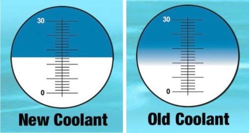
Figure 2 - Tramp oil makes reading a Brix Refractometer difficult.
Disregarding the pure synthetics, most coolants have an oil emulsion base. Left unchecked, microorganisms assimilate organic material and produce organic acids including oxalic, lactic, acetic and citric. Furthermore, biofilm formation is generally considered more of a problem in the summer months because higher temperatures increase the rate of biological processes.10 The mechanism by which microbial corrosion of aluminum occurs is thought to be the result of microorganisms removing phosphate and nitrate more rapidly than calcium or iron from the media in which they grow. By means of this selective and differential utilization of ions, microorganisms make the medium in which they grow progressively more corrosive. This concept is consistent with the relative quantities of calcium, iron, nitrogen and phosphorus found in the microbial cell.11 This phenomenon is important to realize because nitrate is known to inhibit the formation of hydrogenase, which encumbers the corrosion of aluminum.12
Effective coolant cleanout measures have made use of peroxyacetic acid (PAA). PAA is a product used commonly in the food industry and is actually an equilibrium mixture of PAA, water, acetic acid and hydrogen peroxide:
CH3COOOH + H2O ⇔ CH3COOH + H2O2
This chemical has found favored use because the kill dose is achieved at relatively low concentrations (2 to 9 ppm)13 and short contact times (1 to 3 hours). Unlike other biocides, PAA is not affected by pH and water hardness.14 Furthermore, its decomposition products of acetic acid, water and oxygen are innocuous and environmentally acceptable. Other biocides would potentially require treatment before release to a publicly-owned municipality. For metalworking fluids, the use of PAA would be just before a dump. However, at Boeing this chemical has been incorporated for in situ use for chemical process operations, such as hard-metal acid etching in the rinse tanks.15 PAA is typically sold in a much diluted concentration. One such product is Purisan, which is commonly used in the food industry.
To estimate the amount of PAA needed, a helpful mathematical expression is:
Vb = 3.785[VTρpCd/Cnρb]
where
Vb = volume of the Purisan to be added in liters
VT = volume of the tank in gallons
ρp = specific gravity of the rinse water or process solution
Cd = concentration of the intended dilute biocide (~1×10⁻⁵)
Cn = neat concentration of PAA in the Purisan (0.052)
ρb = specific gravity of the Purisan (1.12)
Another mechanism of metalworking-fluid induced corrosion can be caused by coolant that is allowed to dry on the part, causing a condition in which a differential oxidation cell can form (Fig. 3).16 The corrosion pattern typically resembles a halo on the part surface.

Figure 3 - Formation of differential oxidation cell.
Finally, chloride contamination in coolant alone can be enough to cause pitting corrosion directly.17
Solvent cleaning
Although relatively uncommon, aluminum corrosion can be caused by using acetone to solvent-clean parts in ambient light.18,19 Aluminum alloys that are copper rich such as 2024 are photoreactive. The mechanism is that the acetone, in the presence of water, is converted to acetic acid when in contact with the copper intermetallics:20

Consequently, solvent cleaning with acetone of 2024 aluminum should be avoided.21
Incoming water
The most efficient means of rinsing makes use of a double countercurrent rinse (DCCR) system (Fig. 4).22 Because two rinse tanks are used, the most abundant process solution is water, which can contribute significantly to aluminum pitting issues.
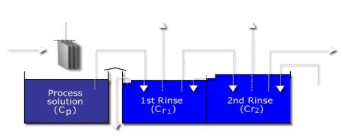
Figure 4 - Double countercurrent rinse.
At Boeing, seasonal variations of pitting occurrences have been noticed. This has been attributed to increased manganese concentration in the incoming water supply, caused by manganese dioxide being deposited by chemical and biological oxidation of dissolved manganese that occurs naturally in surface and ground waters throughout the United States. Consequently, the direct galvanic action of manganese can promote severe localized attack by promoting pitting and crevice corrosion through a combination of electrochemical effects, caused by galvanic coupling between manganese dioxide and the underlying metallic surface.23 Natural levels of chlorination in municipal waters are sufficiently high that manganese reacts with diatomic chlorine to form harmful chloride ions, which are well known to be deleterious to metals.24
MnO2 + 2Cl2 + 2H2O ⇒ MnO4- + 4H+ + 4Cl- - e-
Metal ion hydrolysis acidifies the nucleation site:
Al+3 + H2O ⇔ H+ + Al(OH)+2
This attracts charge-neutralizing counter-ions (chloride) that further disrupt the oxide structure:
Al(OH)+2 + Cl- ⇒ Al(OH)Cl+
Then, with water producing acidic conditions,
Al(OH)Cl+ + H2O ⇔ Al(OH)2Cl + H+
this self-sustaining process leads quickly to stable pitting corrosion.25
Since pitting corrosion will only occur in the presence of aggressive anionic species, ubiquitous chloride ions should be monitored. They alone can cause pitting corrosion26 because chloride ions are relatively small anions with high diffusivity that can interfere with passivation.
Other ions to monitor in rinse waters are copper and carbonate, since these cations have been known to increase the number and depth of aluminum pits.27
Alkaline process solutions
Typically the first tankline process solution is either an emulsion degreaser or alkaline cleaner.
Emulsion degreaser
Since aluminum is only stable in a pH range of 4 to 9, these types of process solutions need to have a corrosion inhibitor package as part of their formulation. Sodium metasilicate (Na2SiO3) is commonly used, but as the solution ages and is continuously exposed to process temperatures above ambient (115° to 170°F), these silicates irreversibly precipitate, leaving the parts vulnerable to alkaline attack (Fig. 5).28
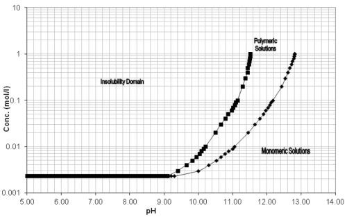
Figure 5 - pH versus concentration of silicates.
The basic mechanism is as follows:
STTP + heat → lower pH → loss of silicates in solution → corrosion
Sodium tripolyphosphate (STTP) is an alkalinity builder constituent, and over time with heat in a hydrolysis reaction, it releases free acid. The free acid release lowers the solution pH. The lowered pH affects the corrosion-inhibitor package component (sodium metasilicate), putting it into a phase of irreversible precipitation (Fig. 6).

Figure 6 - Corrosion caused by alkaline degreaser with depleted silicates.
To prevent the scenario that leads to the phase of irreversible precipitation, the solution pH should be monitored and maintained with the addition of hydroxide (NaOH or KOH) at a pH level dependent on the solution concentration.29
In a production setting, corrosion is at times mistakenly attributed to the emulsion degreaser tank, when in fact the cause is contaminants getting on parts upstream of the tankline. In a recent study, Boeing Research and Technology (BR&T) was asked to identify contaminants that contribute to corrosion in Brulin 815 GD (aqueous degreaser) tanks. The study30 examined the effects of processing various degrease contaminants in Brulin solutions containing varying levels of sodium metasilicate. A key finding was that the following combination of conditions causes corrosion:
- Solid stick Boelube (Boeing proprietary cetyl alcohol-based lubricant), causing solution entrapment.
- A large inclusion.
- A difference in grain structure.
- An old Brulin solution with a low level of corrosion inhibitor.
The fact that several conditions in addition to the use of the proprietary lubricant need to be met to initiate corrosion demonstrates the difficulty sometimes faced when trying to identify the cause of corrosion on a part (Fig. 7).

Figure 7 - Corrosion at hole edge.
Following the alkaline process solution is a rinsing operation. If part rinsing is not performed well, silicate residues that remain on the surface and then enter an acid solution could form an insoluble salicylic acid that might contribute to spot corrosion. This type of surfactant contamination is more likely when a difference in solution surface tension is noted, or perhaps if foaming is observed to be more than usual. Surfactant types can be anionic, cationic or nonionic, so these observations are dependent on the surfactant type used in the cleaner formulation.
Even if an alkaline cleaner is pristine, a poor part load choice can create a galvanic cell, such as when a large basket is used to process a small part load (Fig. 8).
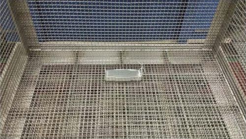
Figure 8 - Small part in large basket.
Alkaline etch
Alkaline etch cleaning has a much higher pH and is intended to perform aluminum metal removal using predetermined etch rates combined with process recipe immersion times. This process involves intended and unintended chemical reactions that need to be understood so that contamination as a result of part processing is known. Below are likely balanced mechanistic chemical reactions for aluminum parts when processed with a formulated alkaline solution containing sodium sulfide.
It also is known that aluminum and copper react with caustic at different rates, potentially leaving loose copper loose containing intermetallic particles on the surface that may lead to galvanic attack in the following rinsing operation. In a similar manner, small amounts of laves phase (MgZn2) on the part surface can lead to a defect known as galvanizing or spangling on 6063 alloys. For this reason, alkaline etch cleaners are commonly formulated with additives such as sodium sulfide (Na2S) to prevent this from occurring. Any added constituent of an etch solution needs to be measured and monitored.31
Caustic with aluminum. First, the naturally occurring aluminum oxide surface is breached yielding sodium aluminate:
2Al2O3 + 2NaOH + Na2S ⇒ 4NaAlO2 + H2S(g)
The reaction with the base aluminum yields more sodium aluminate. The bubbling coming off the part is predominantly hydrogen gas, but the characteristic sulfurous odor of hydrogen sulfide indicates that this gas also is being emitted:
2Al + Al2O3 + NaOH + Na2S + 11H2O ⇒ 3Na[Al(OH)4] + Al(OH)3 + H2S(g) + 3H2(g)
6Al + 2NaOH + Na2S + 9H2O ⇒ Al2O3 + 4NaAlO2 + H2S(g) + 9H2(g)
The resulting sodium aluminate combines with water to form a hydrate, returning to the solution some of its alkalinity:
8NaAlO2 + 16H2O ⇒ 8NaOH + 4Al2O3•3H2O(s)
Caustic with copper-containing phases. Aerospace aluminum is commonly an alloy, and a formulated alkaline solution containing sodium sulfide will likely react with the alloying element. In the case of 2000-series aluminum, the main alloying element is copper. Its sulfides contribute to the formation of a characteristic nearly-black smut layer on the part surface. This likely reaction of the alkaline solution with copper follows. The black smut layer is also a spectral effect of the aluminum base metal being etched around the lesser affected intermetallic particles.
The alloying copper phase is breached, yielding base metals:
Al2Cu ⇒ 2Al + Cu
The reaction with metallic copper yields copper sulfide, and gases:
2Cu + OH- + S-2 +H2O ⇒ Cu2S + 2OH- + H2(g)
These copper oxides remain on the surface of the part and are dark in color, accounting for why aluminum parts are nearly black when coming out of the alkaline-etch rinse tank.
Undesirable etch tank reactions. In the course of part processing, undesirable reactions are unavoidable, such as the production of sodium thiosulfate:
2Na2S + 2O2 + H2O ⇒ Na2S2O3 + 2NaOH
Excessive sodium thiosulfate production will eventually lead to the formation of free sulfur, which can accumulate visibly on the solution surface:
6Al2O3 + 3Na2S2O3 + 3H2O + Na2S + 2NaOH ⇒ 2Al(OH)3 + 3SO2 + 3S + 10NaAlO2 + H2S(g)
Furthermore, alkaline etch process solutions are prone to irreversible hydration of aluminum hydroxide. When the solution is unintentionally cooled, it could result in alumina scale:
2Al(OH)3 ⇒ 2Al2O3 + 3H2O
2AlO(OH) ⇒ Al2O3 + H2O
If there is a sudden drop in aluminum concentration, the likely cause is the precipitation of aluminum oxide along with an increase in alkalinity. High alkalinity would then lead to preferential etching.
Therefore, during times of planned or inadvertent shutdowns, alkaline etch solutions need to be fully measured for all monitored constituent concentrations, etch rate and pH before the restart of part processing.
Deoxidizing
Following alkaline processing is a deoxidizing or desmut operation, depending on whether the prior operation was alkaline cleaning or alkaline etching. These acid solutions are commonly nitric-, sulfuric- or chromic-acid based. As was covered for alkaline etch processing, deoxidizing involves intended and unintended reactions that need to be known, so that contamination from part processing is understood. As an example, below are likely balanced mechanistic chemical reactions for aluminum parts when processed with a nitric-acid based deoxidizing solution.
Nitric acid (HNO3) with aluminum
The aluminum oxides and alloying element smut-layer compounds are made soluble by being converted into their respective nitrate forms:
Al2O3 + 6HNO3 ⇒ 2Al(NO3)3 + 3H2O
Al(OH)3 + 3HNO3 ⇒ Al(NO3)3 + 3H2O
The base aluminum further reacts, producing more soluble aluminum nitrate and hydrogen gas:
2Al + 3HNO3 + 3H2O ⇒ Al(NO3)3 + Al(OH)3 + 3H2(g)
Hydrofluoric acid (HF) with aluminum
The hydrogen fluoride component in this type of deoxidizer solution has numerous mechanisms that produce soluble aluminum fluoride, hydrogen gas, and aluminum hydroxide:
2Al +6HF ⇒ 2AlF3 + 3H2(g)
8Al + 6HNO3 +24HF ⇒ 8AlF3 + 3N2O(g) + 15H2O
Some of the aluminum hydroxide reacts, further producing a duo-anionic solid:
2Al +2HNO3 + 2H2O ⇒ 2Al(OH)3 + 2NO(g)
2Al(OH)3 + AlF3 ⇒ 3AlOF(s) + 3H2O
Hydrogen fluoride is consumed with the production of soluble ammonium nitrate.
Al +3HF + HNO3 ⇒ AlF3 + NH4NO3
Nitric acid and hydrofluoric acid with copper
Similar reactions of nitric acid on the smut layer and copper portion of the intermetallic phases produce soluble copper nitrate and gases:
CuS + 2HNO3 ⇒ Cu(NO3)2 + H2S(g)
Cu + 4HNO3 ⇒ Cu(NO3)2 + 2NO2(g) + 2H2O
To a lesser degree than with aluminum, the hydrogen fluoride is consumed producing copper fluoride and hydrogen gas:
Cu + 2HF ⇒ CuF2 + H2(g)
One of the more interesting aspects in the listing of these desmutting reactions is the large amounts of hydrogen fluoride being consumed. Thus, it is understood that as a desmut tank ages, hydrogen fluoride must be replenished on a regular basis. Failing to do so can (and has) led to incomplete removal of the smut layer. The parts would come out of the following rinse tank and appear to be clean, and actually would have a water-break-free surface. However, a low level of smut layer can remain and become a loose top layer of the following anodic oxide.
Undesirable desmut tank reactions
Although quite rare, one undesirable desmut tank reaction can occur because of sodium thiosulfate drag-out from an aged alkaline etch tank, resulting in elemental sulfur being formed:
Na2S2O3 + 2HNO3 ⇒ S(s) + H2O + SO2 + 2NaNO3
Also, loss of free fluoride can be attributed to drag-out of sodium aluminate from the etch tank:
3NaAl(OH)4 + 6HF ⇒ 2Al(OH)3 + 6H2O + Na3AlF6
Loss of available fluoride
Adding to the importance of hydrogen fluoride in the desmut process is the knowledge that aluminum fluoride tends to form dialuminum hexafluoride, and thereby a loss of free fluoride occurs:
AlF3 ⇒ Al2F6
This larger compound will passivate the aluminum surface if the pH is too high. Thus, older deoxidizer tanks need more nitric acid to counteract this Al2F6 formation effect.
Oftentimes, penetrant inspection indications are the first to notice that a problem may exist with the deoxidizer process solution in the form of contamination or incomplete smut removal. At Boeing, process perturbation experiments led to the conclusion that the combination of short deoxidizer immersion time and long rinse immersion times can cause incomplete smut removal. This condition is not readily apparent during processing, since a water-break-free surface is achieved and the part has no visible discoloration. However, if incomplete smut removal is suspected, the parts could be simply inspected by white-glove hand wiping of the part surface to check for loose nonvisible smut. Of course, possibly of more concern is that this condition left unabated could lead to catastrophic paint adhesion failures (Fig. 9).
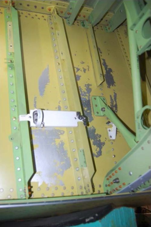
Figure 9 - Paint adhesion failure during assembly.
Deoxidizer process solutions also are prone to anionic (chloride, Cl-) and cationic (copper, Cu+1, Cu+2) contamination that directly results in pitting. For this reason, the copper concentration for several process solutions is required to be measured and monitored.32 Some deoxidizers have additive products, called toners, to counteract the inevitable increase in copper contamination. For those that do not have additive products, the current prescribed remedy is to monitor and dump when approaching the copper limit.
At Boeing, process experience has led to the realization that chromium-based deoxidizers are superior to iron-based deoxidizers when used before chromate conversion coatings.33 The reasoning for this awareness follows.
For iron-based deoxidizers, ferric sulfate is present to oxidize the cuprous (Cu+1) residue that develops on aluminum after alkaline etching to cupric (Cu+2) sulfate. The cuprous is insoluble, whereas the cupric is soluble. As part of the reaction, the soluble ferric will convert to the insoluble ferrous. The nitric present in the product is there to convert the ferrous back to ferric, allowing it to continue oxidizing the copper. In addition, nitric can deoxidize the aluminum, but it will be consumed very quickly:
Fe+3 + Cu+1(s) ⇒ Fe+2(s) + Cu+2
HNO3 + Fe+2(s) ⇒ Fe+3
The ferrous that is not converted back will settle in the tank, or be circulated as an insoluble particle, and if enough of this material is present, it will carry over to the rinse tank. If the rinse is not properly maintained, it will carry over to the conversion coating tank, affecting salt spray performance.
If sodium sulfide (Na2S) is allowed to enter the deoxidizer bath from the alkaline etch, the sodium sulfide will compete with the ferric sulfate. Since the sodium sulfide is not as strong an oxidizing agent, it will not convert as much of the cuprous to cupric, thus allowing copper to remain on the surface of the aluminum and thereby negatively affect salt spray performance of the conversion coating.
Electrolytic processes: stray current
The term stray current often is misused when an investigator is trying to capture some factors that cause problems such as pitting, burning or arcing. Stray and leakage current refer to those electrical currents that flow along paths other than between the cathodes and the parts. The most relevant use of that phrase is as it relates to powered equipment, where the current is no longer confined to the unit. However, standard electrical protocols relating to use of grounding and dielectric unions should mitigate current leakage of this sort.34 Testing can be done using a clamp-on ammeter to measure the stray current levels in the safety ground network at selected points throughout the facility.
Auxiliary equipment should be protected from stray current by the following guidelines.35 Water and steam connections to heat exchangers (and to any other electrically conducting immersion heater) should contain dielectric unions in both the inlet and outlet lines, and use nonconductive bolt washers and sleeves on mounting hardware to avoid making an electrical ground through which stray current will pass. As an example, steam coils can be cathodically protected by making good connection to tank walls. Use of a dielectric union is recommended to prevent stray current from flowing to adjacent equipment. Evidence of auxiliary equipment stray current is usually manifested in the associated piping, and not the parts but the resulting corrosion products will contaminate the process solution with soluble and insoluble iron (Fig. 10).
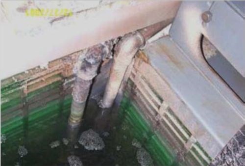
Figure 10 - Evidence of auxiliary equipment stray-current protocols being violated.
In the design and construction of an electrolytic process, consideration should be given to isolation of the tank itself. As an example, plating process specifications36 have flagnotes specific to this issue such as “Tank may be lined with insulation material to prevent stray current. Use a lining material that is chemically inert.”
Apart from defective equipment, another cause of unwanted electrical currents is known to be errant acid on tank lipboards and tank sides, known as operator-induced stray and leakage currents. These acid coated surfaces can provide a preferred current path other than through the electrolyte. This problem is not always readily detected. One observation of this problem is as follows:37
A load of parts are immersed in the tank and the power is activated. The voltage climbs to the normal hard anodizing voltage, initially about 20 to 25 V, and the estimated current is being drawn. After a few minutes or less, the voltage drops to about 15 V or less, yet the current remains constant. The rack is withdrawn from the solution. All electrical contacts are tight. After thoroughly rinsing all the non-conductive buss bar supports and the tank lipboard, the unexpected voltage drop is eliminated. Therefore, to avoid operator induced stray and leakage currents, the shop should at least daily rinse all tank surfaces and related facility components which are exposed to acid spray from the process.
All tank facilities used for electroprocessing need to use electrical ground connections. The integrity of these connections should be checked regularly. The detrimental effects of uncontrolled currents are especially pronounced in high voltage processes such as hard anodizing.
Electrolytic processes: anodize
Boric-sulfuric acid anodizing (BSAA)38 replaced chromic acid anodizing (CAA)39 for commercial aircraft applications in the mid-1990s. Because of reformulation40 (incorporation of organic additive sodium benzoate), this process solution was made more resistant to biocontamination, especially from the fungal matter of Alternaria species.41 A side benefit is that this additive can form a stable complex with aluminum ions and the part is then theoretically further protected from direct pitting attack by chloride contamination.42
Part handling
Part handling is an all-too-often-ignored part of the process that also can directly cause corrosion problems. Ungloved hands are a prevalent source of FOG (fat, oil, grease) laden contaminants that entrain anionic contaminants such as chloride. Also, placing parts that are still slightly wet onto clean Kraft paper in an attempt to keep freshly processed parts clean can lead to sulfate contamination. All papers are manufactured using a sulfuric-acid digestion process and when wetted, a small amount of that acid is leached from the paper that is in direct contact with the part.
Summary
Aluminum corrosion is commonly encountered when performing chemical process operations involving surface finishing, predominantly in preparation for paint application. Prior research and development efforts have established electrochemical measures using potentiodynamic scans to be an effective tool in analyzing the propensity of certain process solutions to contribute to pitting conditions.
Oftentimes it is only during chemical process operations that flaws of incoming materials are revealed. However, when the part details are pristine, many process operations in the tankline can be problematic. Typically, the first process fluids encountered are coolants, followed by solvent cleaning, alkaline clean/etch and deoxidizing/desmutting. Several of the tankline operations involve intended and unintended chemical reactions. Mechanistic evaluations of these processes were provided so that the propensity for aluminum corrosion can be better understood.
Further explanation was provided for the role of incoming water that is used for process solution make-up and the myriad of rinse tanks. Seasonal variation can account for mineral contamination of plant water used, and chemical reactions were provided as possible causal conditions for observed pitting.
When electrolytic processes are employed, stray current can affect auxiliary equipment, thereby introducing deleterious contaminants into process solutions because of the corrosion products of these piping, fittings and fasteners for heating and cooling units.
Finally, improper part handling can cause aluminum corrosion problems such as when wet parts are placed on brown Kraft paper.
Strict adherence to process specification controls, regular monitoring of suspect contaminants and sound general housekeeping best practices will alleviate many aluminum part processing corrosion occurrences.
References
1. J.D. Minford, Handbook of Aluminum Bonding Technology and Data, M. Dekker, New York, 1993; p. 110.
2. A.M. Beccaria & G. Poggi, British Corrosion Journal, 21 (1), 19-22 (1986).
3. W.B. Engel, Proc. Conf. Nat’l. Assoc. Corros. Eng., 1970; pp. 588-596.
4. J.W. Dunn, “Spot Discoloration on 7000 Series Aluminum Alloys,” Boeing (1963).
5. G.E. Kiourtsidis, et al., Corrosion Science, 41 (6), 1185-1203 (1999).
6. J.R. Galvele, in Passivity of Metals, R.P. Frankenthal & J. Kruger, Eds., The Electrochemical Society, Princeton, NJ, 1978: pp. 285-387.
7. N. Birbilis & R.G. Buchheit, J. Electrochem. Soc., 152 (4) B140-151 (2005).
8. A.A. Gerasimenko, Zashchita Metallov, 15 (4) (1979) (in Russian).
9. S.G. Choudhary, Hydrocarbon Processing, 77 (5), 91-102 (1998).
10. B. Little, P. Wagner & F. Mansfield, International Materials Review, 36 (6), 253-272 (1991).
11. G.C. Blanchard & C.R. Goucher, Developments in Industrial Microbiology, 6, 95-104 (1964).
12. Air Force Aero Propulsion Laboratory, “Mechanism of Microbiological Contamination of Jet Fuel and Development of Techniques for Detection of Microbiological Contamination,” Technical Documentation Report No. APL-TDR-64-70, Part I (1964).
13. J.F. Kramer, Proc. NACE Corrosion/1997, Paper No. 404, NACE International, Houston, TX, 1997.
14. ibid.
15. W.J. Fullen, Plating & Surface Finishing, 90 (5), 10-15 (2003).
16. See Note 9.
17. E.W. Pfaff & F. Luke, Boeing Manufacturing Development Report (MDR) 2-41051, “Pitting Corrosion Problem of 7000 Al Alloys Production Parts,” (1990).
18. C.R. Clayton, G.P. Halada & S.V. Kagwade, in Proc. Symposium on Critical Factors in Localized Corrosion III, Jerome Kruger 70th Birthday Symposium, The Electrochemical Society, Pennington, NJ, 1999; pp. 223-233.
19. S.V. Kagwade, et al., J. Electrochem. Soc., 47 (11), 4125-4130 (2000).
20. S.V. Kagwade & C.R. Clayton, in Passivity and Its Breakdown, P.M. Natishan, et al., Eds., The Electrochemical Society, Pennington, NJ, 1998; p. 631.
21. S.V. Kagwade & C.R. Clayton, Electrochimica Acta, 46 (15), 2337-2342 (2001).
22. J.K. Unangst & W.J. Fullen, Plating & Surface Finishing, 91 (12), 44-49 (2004).
23. W.H. Dickinson & R.W. Pick, Proc. NACE Corrosion/2002, Paper No. 02444, NACE International, Houston, TX, 2002.
24. J. Tverberg, K. Pinnow & L. Redmerski, Proc. NACE Corrosion/1990, Paper No. 151, NACE International, Houston, TX, 1990.
25. Z. Szklarska-Smialowska, Corrosion Science, 41 (9), 1743-1767 (1999).
26. G.S. Frankel, J. Electrochem. Soc., 145 (6), 2186-2198 (1998).
27. D. Wong & F.H. Cocks, Study of Aluminum Corrosion in Aluminum Solar Heat Collectors Using Aqueous Glycol Solution for Heat Transfer - Annual Technical Progress Report July 30, 1979 – July 31, 1980, U.S. Department of Energy (1980).
28. C. Saunders, K. Evans & N. Sagers, Wash Solution Bath Life Extension for the Space Shuttle Rocket Motor Aqueous Cleaning System, Thiokol Corporation, Brigham City, UT, 1991.
29. Boeing Process Specification BAC5763, revision L, “Emulsion Cleaning and Aqueous Degreasing” (Nov. 27, 2013).
30. Boeing Summary Report (SR) 12724 (Nov. 28, 2011).
31. Boeing Process Specification BAC5786, revision L, “Etch Cleaning of Aluminum Alloys” (Aug. 2, 2011).
32. Boeing Process Specification BAC5765, revision V, “Cleaning and Deoxidizing Aluminum Alloys” (Nov. 14, 2011).
33. W.J. Fullen, Metal Finishing, 104 (12), 34-42 (2006).
34. Boeing Standard D38201-12, “Grounding and Shielding” (Aug. 4, 1999).
35. Boeing Standard D38512-19, “Chemical Heat Exchangers, In-Tank, Heat Exchanger/Plate” (Oct. 13, 2006).
36. Boeing Process Specification BAC5722, revision E, “Copper Plating” (June 3, 2008).
37. Boeing MDR 2-36249, “Hard Anodize Process Problems” (1981).
38. Boeing Process Specification BAC5632, revision D, “Boric Acid − Sulfuric Acid Anodizing” (Aug. 3, 2004).
39. Boeing Process Specification BAC5019, revision U, “Chromic Acid Anodizing” (June 3, 2005).
40. J.C. Oleund, W.J. Fullen & D.L. Crump, U.S. patent 6,149,795 (2000).
41. W.J. Fullen, See Ref. 15.
42. Y. Isobe, S. Tanaka & F. Hine, Corrosion, 46 (10), 798-803 (1990).

About the authors
W. John Fullen has been with the Boeing Company for more than 29 years, at present in the Boeing Research and Technology (BR&T) organization, first in advanced composites but predominantly in chemical technology in support of tankline operations and the Boeing supply base. Prior to that, he worked at H.B. Fuller Co. in the area of adhesives. He holds a B.S. in Chemical Engineering from the University of Minnesota.
Jennifer Deheck was employed at Boeing during the course of this study and worked as a Chemical Process Engineer.
Related Content
A Chromium Plating Overview
An overview of decorative and hard chromium electroplating processes.
Read MoreHow to Address Declining Powder Coating Coverage Over Time
Fine particles from reclaim could be to blame for powder coating problems that emerge over time. Avoid problems by keeping hooks clean, maintaining guns and using reclaim powder quickly to avoid accumulation of fines.
Read MoreRead Next
A ‘Clean’ Agenda Offers Unique Presentations in Chicago
The 2024 Parts Cleaning Conference, co-located with the International Manufacturing Technology Show, includes presentations by several speakers who are new to the conference and topics that have not been covered in past editions of this event.
Read MoreEducation Bringing Cleaning to Machining
Debuting new speakers and cleaning technology content during this half-day workshop co-located with IMTS 2024.
Read MoreDelivering Increased Benefits to Greenhouse Films
Baystar's Borstar technology is helping customers deliver better, more reliable production methods to greenhouse agriculture.
Read More


.jpg;maxWidth=300;quality=90)
