A Microscopic Study of Chromium Plating (1964)
This 1964 paper describes the first time that anyone had been able to photograph work of this type on chromium - the direct microscopic observation of the deposition of chromium on nickel and other basis metal surfaces. This classic study provided information on the effect of the surface condition of the substrate and plating variables on the initial stages of deposition, covering the growth to form a coherent deposit, and the later development of the cyclic pattern of cracking with its associated hydrogen gas evolution.
by
M.H. Jones & J. Saiddington
Department of Chemistry
Ontario Research Foundation
Toronto, Ontario, Canada
Technical Editor’s Note: From time to time, it has been our intent to present seminal papers from past issues of NASF/AESF journals that are of such significance that, decades later, they bear another look. It is hoped that our rich and illustrious heritage might inspire others to reinvigorate the technological prowess of our industry. This paper last ran in the AESF Journal of Applied Surface Finishing in 2007 [JASF, 2 (3), 174-184 (2007)], and was part of AES Research Project No. 14, It was originally presented at the AES 48th Annual Convention, Boston, Massachusetts, June 18-23, 1964 and published in the Technical Proceedings of the American Electroplaters Society, 48, 32-40 (1964).
As noted by J. Douglas Thomas (GM Research Laboratories, Electrochemistry Dept., Warren, MI), Session Chair at the Boston Convention, “This has been the first time, to our knowledge, that anyone has been able to photograph work of this type on chromium. ∙∙∙ trying to get a light near your plating cell is quite an achievement.” The work turned out to be a significant study from the AES Research Program. The paper was delivered when electrodeposited chromium was of paramount interest to the surface finishing industry. Decorative chromium finishes were the most significant segment at the time, particularly in the automotive industry. The original objective of AES Research Project #14 was to determine basis metal effects in plating, with emphasis on the influence of the properties and preparation of a basis metal on electrodeposit durability. In light of the times, the work eventually concerned itself with chromium, specifically the corrosion protection afforded by decorative chromium over nickel. However, this particular phase of the work excited those in the field, as it afforded the first in situ look at an electrodeposit forming and growing. The paper was illustrative of the caliber of results coming from the AES Research Program and from the Ontario Research Foundation. A printable version of this paper and a transcript of the discussion following the presentation at the Boston Convention are available by clicking HERE.
ABSTRACT
An apparatus is described for the direct microscopic observation of the deposition of chromium on nickel and other basis metal surfaces. The study has provided information on the effect of the surface condition of the substrate and plating variables on the initial stages of deposition, covering the growth to form a coherent deposit, and the later development of the cyclic pattern of cracking with its associated hydrogen gas evolution. This work constitutes an extension of the preliminary investigation of Brittain and Smith and the microscopic observations are considered in relation to the mechanism of chromium plating.
Introduction
During the past few years there has been considerable commercial interest in the influence that the chromium layer can have on the corrosion performance of decorative nickel-chromium deposits. It has been clearly demonstrated by a number of groups1-5 that by increasing the chromium thickness in the crack-free condition, or by the use of the so-called micro-cracked chromium or duplex chromium, a remarkable increase in outdoor durability can be obtained.
To provide more basic information on this system, AES Research Project No. 14 has undertaken a study of the factors that influence the initial deposition of chromium on nickel surfaces and the subsequent growth pattern. For this purpose, a technique has been developed which permits direct observation of the progress of plating under the microscope. Such an approach is not new6-8 but in the present case emphasis has been placed on providing continuity of operation so that the condition of the basis metal before and after chemical treatment, and the plating process, can be followed without interruption.
This report is concerned with plating from a chromium bath (250 g/L) in which sulfuric acid only has been used as the catalyst. The effect of varying the type of basis metal, its activation treatment and the plating conditions such as temperature, ratio and current density have been studied in exploratory experiments. As these variables appear to show little effect on the relationship between the initial stages of deposition and the subsequent progress of plating after a coherent deposit has formed, observations made on the two phases are discussed separately.
Experimental
Since the objective was to follow the complete plating process under the microscope, the major consideration in the design of the plating cell and its auxiliary equipment was to provide versatility in operation.
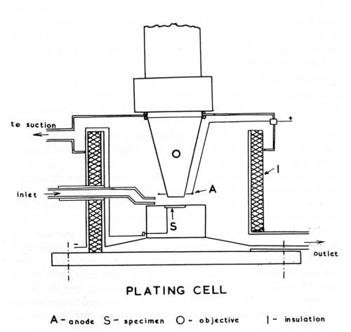
Figure 1 - Schematic diagram of plating cell.
The cell, which is illustrated diagramatically in Fig. 1, consisted of a Pyrex glass vessel of approximately 100 cc capacity (internal diameter 5 cm, height 5 cm) and was furnished with two inlet and two outlet tubes. In order not to make the cell cumbersome by the incorporation of thermostat controls and heating elements, the problem of maintaining constant temperature was approached by using a constant flow of an externally heated solution. By this means a temperature control of ± 1°C was achieved. For rapid evacuation of the plating solution, the cell was provided with a tapered bottom and a second outlet to bypass the constant level overflow. By arranging for the solution to be delivered close to the surface of the specimen, a cross current flow was maintained which provided agitation and permitted elimination or control of the obscuring effect of gas bubble formation during plating. The various solutions such as the alkaline cleaner, acid etch, plating solution, distilled water, etc. were kept at the required temperature in four-liter Pyrex containers and connected to the delivery tube of the plating cell by a common manifold. Provision was made for the recirculation of solution during long plating sequences and the microscopic equipment was protected from acid fumes by a cover for the cell which was connected to an exhaust system.
The cell was mounted on a heavy base plate which, in turn, was attached to the stage of a Leitz Panphot microscope that permitted adjustment in three planes for accurate leveling of the surface under view. Microscopic observation and photomicrography were made through an accessory immersion lens which permitted a working distance of up to 8 mm and a magnification up to 200×. For single shot photography a 35 mm camera attachment was employed and, where a continuous record of transient changes was required, a Kodak Cine Special camera was used.
Direct current was supplied from lead storage batteries and the anode consisted of a platinum wire wound in the form of a spiral around the objective extension. A general view of the setup is shown in Fig. 2.
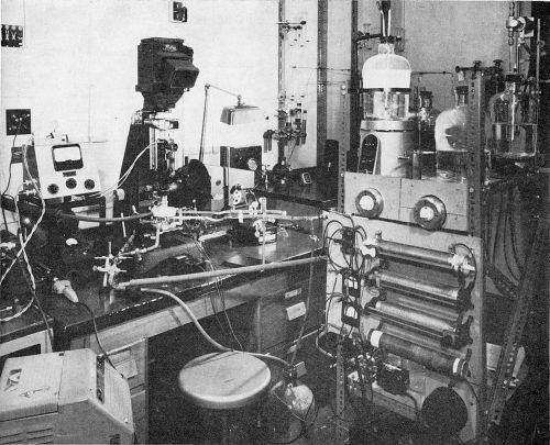
Figure 2 - General view of arrangement for plating under the microscope.
Specimens ranging in size from one cm square to one mm in diameter were mounted in cold setting Araldite resin (No. 502) and, in most cases, were metallographically polished to produce the flat mirror type surfaces necessary for satisfactory microscopic observation. Experiments with a Watts and a bright nickel in the as-plated condition showed essentially the same pattern as for equivalent polished surfaces although observation was considerably more difficult.
Chromium plating solutions were prepared from reagent grade chemicals and were not dummied as this practice darkened the solutions sufficiently to make visual observations impractical. They were usually discarded after one or two experiments. Preplating treatments such as anodic or cathodic alkaline cleaning (NaOH, 45 g/L; Na2CO3, 30 g/L) and etching in sulfuric acid (8% H2SO4; 1 g/L KI) and hydrochloric acid (20% HC1) were carried out in the plating cell so that the same area of observation on a specimen could be followed through the complete cycle of operations.
Microscopic observations
The visual observations made on the course of a number of plating experiments covering a range of chromic acid to sulfuric acid ratios, bath temperatures, current densities and different basis metals and surface activation treatments are summarized in Table I. The effect of these variables on the initial stages of deposition and the growth stage after a coherent deposit has established are discussed separately.
Table 1 - Details of plating experiments.
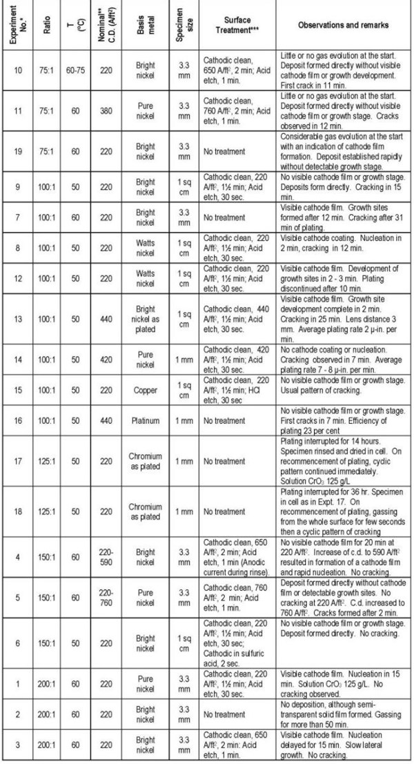
* The Expt. Nos. refer to the order in which they were performed. The tabulation groups the experiments by CrO3 to H2SO4 ratio.
** Current density in observation areas approximately 80% of these values.
*** Cathodic clean: NaOH, 45 g/L; Na2CO3, 30 g/L; Temperature, 70-75°C. Acid etch: 8% H2SO4; 0.1% KI; Temperature, 20-25°C.
Initial stages of deposition
The pattern observed in the initial stages of deposition is very dependent upon the plating conditions and the activity of the basis metal surface. The time required to establish a continuous deposit may vary from a few seconds, when no intermediate steps can be distinguished, to several minutes when a visible cathode film forms and chromium deposition takes place at isolated locations and grows laterally. With a slow growth stage, general nucleation over the whole surface may occur before the final formation of a coherent deposit.
The most important variables affecting this change in pattern are the chromic to sulfuric acid ratio, the surface condition of the base and, to a lesser extent, the current density. Very rapid establishment of the deposit during which no visible cathode film can be detected is observed with low ratios, an active base and moderate to high current densities (Expt. Nos. 9, 10, 11, 12, 14 and 15). Also, at the lowest ratio, 75:1, there is little gassing from the surface when the current is applied.
As the bath ratio is increased above 100:1, and particularly when the substrate is inactive, a well defined cathode film develops under which nucleation of chromium occurs at a few isolated points, the deposit spreading slowly over the surface. This cathode film, which is solid and semi-transparent, is specific to the nucleation phase on an unreceptive surface and is different from the fluid type film that is generally observed in chromium plating and which is not discernible by the present technique. Vigorous gas evolution from the surface is a concomitant factor with the appearance of a solid film. At sufficiently high ratios and with no surface activation (Expt. No. 2), the solid cathode film forms without being followed by chromium deposition.
At intermediate ratios (100:1 to 150:1), the importance of the surface condition is very pronounced and the formation of growth sites and their development to a continuous deposit can occupy a period varying from seconds to 20 minutes or more. This effect, with nickel as the basis metal, is clearly demonstrated by Expt. Nos. 4, 5 and 6. In this series the only variable is the surface treatment and it is apparent that an efficient cathodic alkaline cleaning followed by an acid etch (Expt. No. 5) results in the rapid formation of a deposit without any visible intermediate steps. However, when the nickel surface was inadvertently made anodic during a water rinse (Expt. No. 4), the surface condition created, presumably the formation of a nickel oxide film, was so unfavorable to the chromium deposition reactions that only hydrogen evolution was observed for 20 minutes. A subsequent increase in current density led to the development of the solid cathodic film followed by nucleation and deposit growth.
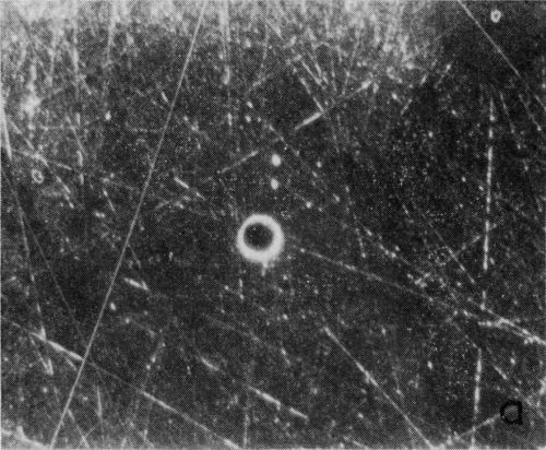
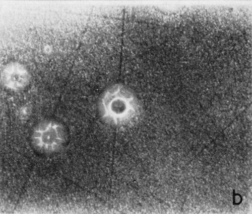
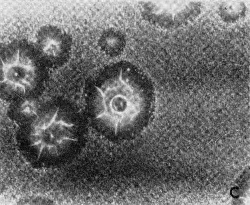
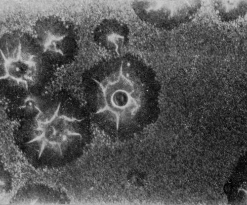
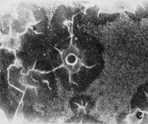
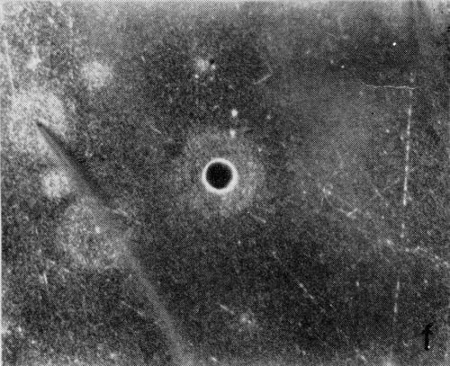
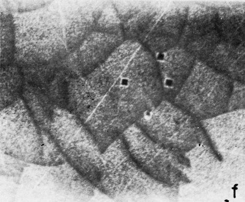
A typical series of photomicrographs illustrating the phenomenon of delayed nucleation and the slow development of growth sites is shown in Fig. 3. These were taken during plating from a chromium bath with a 100:1 ratio which was operated at 60°C and where there was no activation of the nickel base (Expt. No. 7). The first photomicrograph (Fig. 3a) shows the nickel surface before plating and the small circle in the center is an indentation mark made for reference purposes. The initial growth sites and the cathodic film, which largely obscures the polishing marks on the original surface, can be seen in Fig. 3b, and it was generally noted that for this type of condition nucleation occurred at defects on the basis metal surface. The subsequent lateral growth from these sites is clearly illustrated in Figs. 3c, 3d and 3e, the latter showing actual peeling of the cathode film. The last photomicrograph (3f), taken after 23 minutes of plating, is an illustration of the appearance after the formation of a coherent deposit. Hydrogen gassing from one of the original growth sites can be detected, indicating that it has acted as a center for the development of a gas pit.
(a)
(b)
(c)
(d)
(e)
(f)
Figure 3 - Development of growth sites during initial stages of deposition. Magnification 75×. Expt. No. 7: (a) original surface; (b) 14 min of plating; (c) 14½ min of plating; (d) 15½ min of plating; (e) 16 min of plating; (f) 23 min of plating.
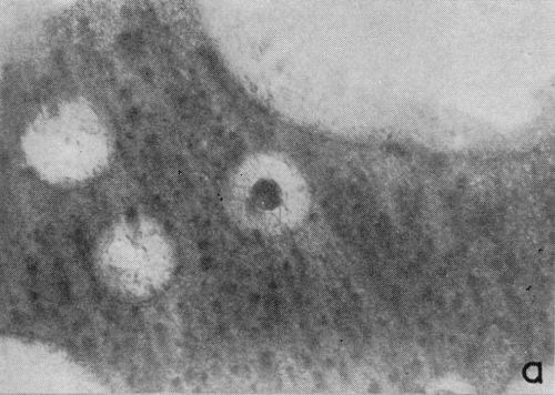
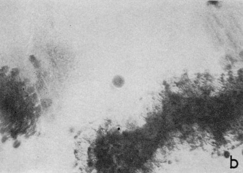
One particular observation that was made for plating conditions yielding a well defined cathodic film is that gas evolution occurs preferentially from the film as opposed to the chromium deposit, even when there are only fragments remaining on the surface. This suggests that the film has a lower hydrogen overvoltage or provides the condition for nucleation of gas bubbles. The effect is illustrated in the two photomicrographs shown in Fig. 4 which were taken with oblique lighting during plating from a 200:1 ratio bath (Expt. No. 3). In the first (Fig. 4a), a continuous deposit has already formed under the non-metallic film and the original growth sites are visible due to its partial removal. The small dark spots represent gas bubble generating sites and their almost complete absence from the exposed chromium surface is more distinct in Fig. 4b where little of the solid cathode film remains.
(a)
(b)
Figure 4 - Residual cathode film, oblique illumination. Magnification 100×. Expt. No. 3: (a) 18 min of plating; (b) 25 min of plating.
Later stages of plating
Once a continuous deposit is formed, the progress of plating follows a definite course which is dependent on the sulfate ion concentration, temperature and current density. The conditions occurring during the initial phase of deposition do not appear to exert any gross effect on the subsequent plating pattern.
One of the features of chromium plating is the cracking pattern that develops at certain combinations of bath ratio and temperature (for example, a ratio of 100:1 and a temperature of 60°C or less) once the deposit thickness exceeds a threshold level of approximately 35 micro-inches. Current density also has an influence on whether cracking will occur but its effect is of less importance than the other variables. Brittain and Smith7 have shown that cracking is a cyclic phenomenon, new sets of cracks occurring at regular time intervals within a very restricted area, their formation being accompanied by vigorous hydrogen evolution which slowly subsides until there is no visible bubble formations from the surface before the next series of cracks develop. These observations have been confirmed in the present work and it has also been established that the density of cracks increases progressively with each cycle. Initially, within a localized area, a single crack line appears and branched cracks of greater density develop in successive cycles until a maximum level of branching is reached which depends upon the plating conditions.
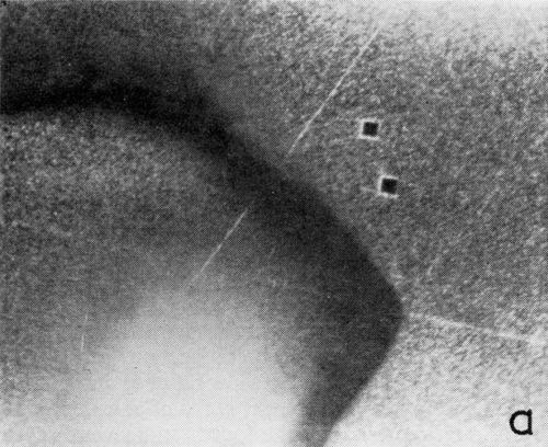
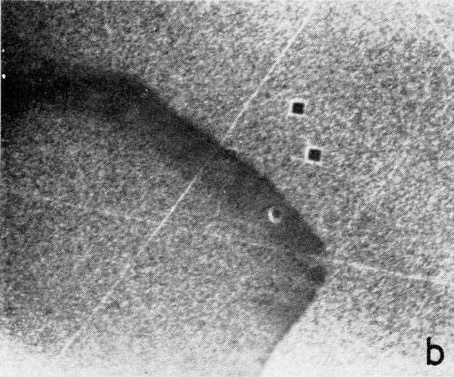
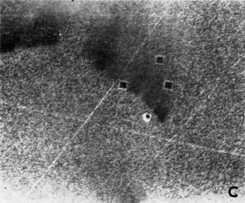
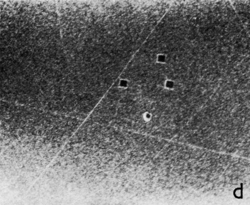
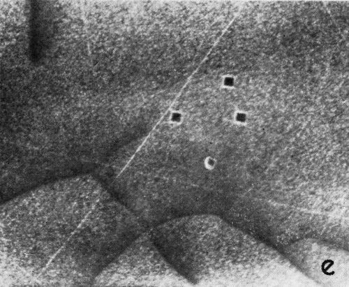
A series of photomicrographs illustrating the relationship between crack formation and hydrogen evolution for the first cracking cycle and the subsequent increase in crack density is shown in Fig. 5. These observations were made during plating from a 75:1 ratio bath operated at 60°C (Expt. No. 10) and, again, the small squares are indentations made in the surface of the basis metal for identification. The first four photomicrographs (5a thru d), taken at 10 to 15 second intervals, show the sequence of events for the initial crack cycle. Healing of the crack at certain points with the cessation of hydrogen evolution from these locations can be seen (5b and 5c), and it is followed by a period of quiescence (5d) before the development of the next series of cracks. Later stages of cracking, representing the fourth and seventh cycles respectively, are illustrated in Figs. 5e and 5f. In this experiment the time between successive cycles was approximately 3 minutes and gassing from the cracks lasted for 30 to 40 seconds. Generally, it was found that the duration of gas evolution and the time between cycles is inversely proportional to current density. Also, it was noted that the hydrogen evolution, at least qualitatively, appears to increase as the density of cracking increases.
(a)
(b)
(c)
(d)
(e)
(f)
Figure 5 - Relationship between cracking and gas evolution. Magnification 75×. Expt. No. 10: (a) initial cracking at 11th min of plating; (b) 11 min, 10 sec; (c) 11 min, 20 sec; (d) 11 min, 35 sec; (e) 23 min of plating; (f) 31 min of plating.
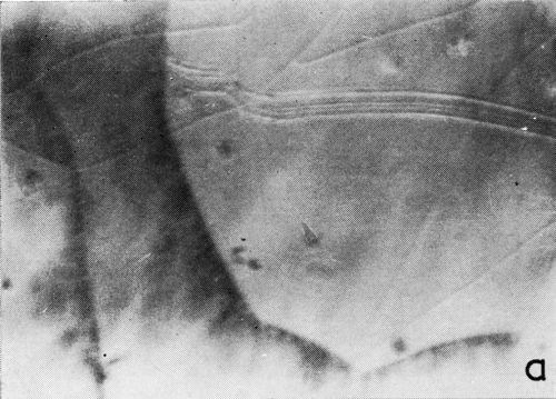
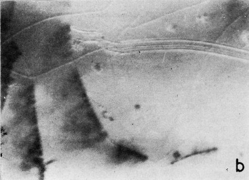
A clearer illustration of the fact that gas is evolved from the cracks and the progress of healing is shown in the two photomicrographs of Fig. 6. These were taken at a 5 to 7 second interval under oblique illumination of an early cracking cycle (Expt. No. 9).
(a)
(b)
Figure 6 - Gas evolution from cracks; oblique illumination. Magnification 75×. Expt. No. 9.
To obtain a better understanding of the mechanism of hydrogen evolution at the crack locations a number of experiments were carried out and these are listed in Table 2. Perhaps the most significant observation is that hydrogen evolution from the cracks commences immediately when the current is applied after a cracking cycle is interrupted, and that this occurs even if the specimen is washed and the solution replaced. The implication is, therefore, that this phenomenon is not the result of a nucleation effect causing desaturation of the solution or the cathode film. Similarly, the fact that the cyclic pattern is independent of the type of basis metal, including steel, various forms of nickel, copper and platinum, and that gassing can be initiated after long periods of current interruption, indicates that the origin of the hydrogen evolved at the moment of cracking is not that which has diffused into the deposit or the base. The evidence suggests that it is due to a low hydrogen overvoltage within the cracks and that it ceases as the result of bridging by the chromium deposit. A similar conclusion was reached by Brittain and Smith.7
Table 2 - Experiments on hydrogen gas evolution at cracks.
|
Type of Experiment |
Observation |
Remarks & Inference |
|
1. Interruption of current during gassing from cracks. |
Gassing continues for the usual length of time after resumption of the current. |
Cracks - a source of bubble generating spots. |
|
2. Variation of current density. |
The duration of hydrogen gas evolution from the cracks is inversely proportional to the current density. |
Healing action by deposition of chromium at the crack edges. |
|
3. Reversal of current for brief period (10 sec) during gassing. |
No marked difference. Gassing continues for approximately the same length of time after resumption of current. |
The reversal of current for short period attacks primarily the edges of the cracks. |
|
4. Reversal of current for longer period (1 min). |
Gassing from the whole surface for long periods (up to 10 min) on resumption of current. Cracks develop when gassing subsides. |
Anodic stripping results in formation of new surface on which the deposition process starts from the beginning. |
|
5. Removal of cathodic film by rinsing the surface with distilled water. |
Gas evolution at the cracks after switching the current on. |
Hydrogen discharge at the cracks not associated with cathode film. |
|
6. Deposition on a surface in which cracks were revealed by anodic stripping. |
Gas evolution at the cracks lasting longer period of time than within a cyclic sequence. |
Longer period required to bridge larger cracks. |
|
7. Substitution of chromium solution by sulfuric acid at sequence of cracking. |
Gas bubble generation at the cracks for long period of time (10 - 15 min). |
Low hydrogen overvoltage at the cracks. |
|
8. Cathodic charging of the surface in sulfuric acid at the sequence of cracking. |
Deposition commences from the beginning followed by usual cyclic pattern of gassing and quiescence. |
Cathode charging alters surface characteristics and deposition starts as if on a new specimen |
Each set of cracks occurs in discrete areas of approximately 1 sq mm and, if a specimen of this size is employed, exactly the same sequence of events is observed. In following the current/voltage characteristics on such specimens, where only one crack cycle can occur at a time, it was found that there are no major changes in current or voltage between periods of quiescence and crack formation. A small jump in current representing 0.2 to 0.3% of the total was observed to coincide with the burst of gassing from freshly formed cracks. This is probably due to a decrease in hydrogen overvoltage or an increase in conductivity of the cathode layer through the stirring effect in the solution.
As might be expected, for high ratio baths (150:1 to 200:1), and even for low ratio baths at a sufficiently high temperature, which give crack-free deposits, the cyclic phenomenon is not observed. Hydrogen evolution occurs continuously from discrete points on the surface throughout plating and, on one occasion, it was noted that the locations of gas bubble formation did not change significantly over a considerable period of time. This provides additional evidence for the cause and effect relationship between cracking and hydrogen evolution which is further substantiated by the observations made on transversing the transition region between cracked and crack-free plating. In one experiment (Expt. No. 10), the temperature of plating was gradually increased from 60 to 75°C after the cyclic pattern of cracking had been well established. It was observed that the length of the cycles progressively increased, together with the period of gassing from the crack locations, until a stage was reached when there was a complete absence of the quiescent phase, hydrogen evolving continuously from a number of points on the surface. In part, this increase in length of the cycle may reflect a decrease in cathode efficiency with temperature. The condition of crack-free plating was maintained for approximately 30 minutes and, on slowly lowering the temperature, the cracking cycle reappeared in isolated areas on the edge of the specimen and gradually spread towards the center. During this period the unusual condition existed in which there were two distinct regions, one showing continuous gassing with no cracking and the other following the cyclic pattern of cracking and hydrogen evolution.
Discussion
The more important observations covering the influence of the chromic to sulfuric acid ratio on the initial phases of deposition and the subsequent cracking phenomenon are summarized briefly in Table 3. These form the basis of the following discussion.
Table 3 - Summary of observations on initial and later stages of deposition.
|
Ratio of CrO3:SO4- |
Initial Stages |
Later Stages |
|
|
Well-activated Surface |
Inactive Surface |
|
|
|
75:1 |
No visible cathode film. Rapid deposition. Little hydrogen evolution. |
Indication of cathode film but rapid establishment of deposit. Considerable hydrogen evolution. |
Cyclic cracking pattern. No cracking at very high temperatures. |
|
100:1 |
No visible cathode film. Rapid deposition. Moderate hydrogen evolution. |
Solid cathode film. Delayed nucleation and slow growth stage. Considerable hydrogen evolution. |
Cracking at high and moderate current densities. |
|
150:1 |
No visible cathode film. Rapid deposition. Moderate hydrogen evolution. |
Solid cathode film. Delayed nucleation and slow growth stage. Considerable hydrogen evolution. |
Cracking at high but not moderate current densities. |
|
200:1 |
Solid cathode film forms. Delayed nucleation and slow development of growth sites. Considerable hydrogen evolution. |
Very high rate of hydrogen, evolution. Slow development of solid cathode film. No deposit formed. |
No cracking. |
Initial stages
The two factors which have the greatest effect on the initial pattern of chromium deposition are the sulfate concentration and the condition of the basis metal surface. These appear to be interrelated since a high sulfate content and no activation of the base give a similar pattern to that obtained at low sulfate concentrations when there has been an efficient activation treatment. In effect, both a low catalyst level and an inactive substrate lead to delayed nucleation of chromium, with a slow development of growth sites, and result in solid cathode films which are semi-transparent. These solid films occur only in the initial stages, breaking into fragments and dispersing once a continuous deposit is established. The reduction in sulfate concentration also causes a marked increase in the hydrogen evolution during this phase and an analogous effect due to the substrate condition was observed.
It is well known that chromium is not deposited from pure chromic acid, the cathode reaction being essentially 100% hydrogen discharge, and a number of suggestions9-12 have been made for the role played by the catalyst. The supposition that the sulfate ion controls the nature and extent of the cathode film10-12 such that the diffusion of chromate ions to the electrode surface is hindered, while the penetration of hydrogen ions is still permitted, is consistent with the present observations. However, it is evident that the nature of the basis metal surface must also affect the electrode reactions favoring those that give rise to hydrogen discharge and to the formation of the insoluble chromium compounds which constitute the solid cathode film. In addition, much higher rates of hydrogen evolution occur during this stage as compared to that when a coherent deposit has formed, which may indicate that hydrogen atoms are involved, at least in part, in the reduction reactions producing the film. Snavely9 has shown that hydrogen atoms reduce hexavalent chromium to the trivalent state.
Later stages
The discontinuous nature of the hydrogen evolution pattern for plating conditions that give cracked deposits is the most important factor. As hydrogen evolution occurs for only 15 to 20% of the time interval between successive cycles, and the overall efficiency for chromium deposition was shown to be 20% by anodic stripping, it follows that the discharge of chromium ions to give metallic chromium cannot be the sole cathode reaction taking place during periods of quiescence. Thus, during this period, the current efficiency for the production of other reduced species, such as trivalent chromium, must increase or hydrogen atoms must disappear by some route other than the formation of molecular hydrogen. If the essential constancy of the current and voltage during a cracking cycle implies that the distribution of current between electrode reactions involving hydrogen ions and chromium ions does not change significantly, then the latter is more likely.
There are three possible routes for the disappearance of hydrogen atoms:
- Diffusion into the deposit.
- Co-deposition with chromium.
- Reduction reactions in the cathode film.
Consequently, quantitative data on the rates of hydrogen evolution and the formation of trivalent chromium should throw considerable light on the electrode reactions. Such information must be obtained over single cycles to avoid averaging effects. In addition, there is the effect of increased hydrogen evolution with cracking density to be taken into consideration.
It has been reported7,13 that chromium has a banded structure which appears to correspond to the cracking cycles and it is probable, therefore, that the nature of structure of the deposit changes with the hydrogen evolution pattern. An optical and electron microscopic study of deposits prepared under different plating conditions is contemplated to provide more information on this phenomenon.
Acknowledgements
The authors are indebted to Mr. S.J. Majka, Department of Metallurgy, for many valuable suggestions during the development of the microscopic technique.
Acknowledgement is also due to the AES Research Committee: Dr. D.G. Foulke, Sel-Rex Corporation, Chairman; Dr. H.J. Wiesner, The Bendix Corporation, Vice Chairman; and J.D. Thomas, General Motors Corporation, District Supervisor; and the Project Committee: W.M. Tucker, Eastman Kodak Company, Chairman; A.J. Adams, Armalite Company; E.P. Blandy, Canadian Arsenals Limited; C.F. Nixon, General Motors Corporation; Dr. J.V. Petrocelli and H. A. Skelton, International Nickel Company; Dr. J. Stareck, Metal and Thermit Company; Dr. R.B. Saltonstall, Udylite Corporation; Dr. L. Weisberg and Kergan Wells, W.W. Wells Limited; for their continued interest and many contributions to this work.
This investigation forms part of the Group Research Project sponsored jointly by the American Electroplaters Society and the Province of Ontario through its Department of Planning and Development.
References
1. R. Dow & J.E. Stareck, Proc. Am. Electroplaters' Soc., 40, 53 (1953).
2. E.J. Seyb, A.A. Johnson & A.O. Tulumello, Proc. Am. Electroplaters' Soc., 44, 29 (1957).
3. H.A. Brown, M. Weinberg & R.J. Clauss, Plating, 45, 144 (1958).
4. W.H. Safranek, H.R. Miller, R.W. Hertz & C.L. Faust: Plating, 47, 405 (1960); Proc. Am. Electroplaters' Soc., 47, 96 (1960).
5. E.J. Seyb, Proc. Am. Electroplaters' Soc., 47, 209 (1960).
6. H.J. Pick, Nature, 176, 693 (1955).
7. C.P. Brittain & G.C. Smith, Trans. Inst. Met. Finishing, 33, 289 (1956).
8. H.J. Pick & J. Wilcock, Trans. Inst. Met. Finishing, 35, 298 (1958).
9. C.A. Snavely, Trans. Electrochem. Soc., 92, 537 (1947).
10. E. Muller, Arch. fur. Metallkunde, 2 (4), 110 (1948).
11. D. Reinkowski & C.A. Knorr, Zeit. fur. Elektrochem., 58, 709 (1954).
12. M. Kappel & H. Gerisher, Zeit. fur. Elektrochem., 64, 235 (1960).
13. H. Fry, Trans. Inst. Met. Finishing, 32, 107 (1955).
TRANSCRIPT from Educational Session A
CHAIRMAN J. DOUGLAS THOMAS (GM Research Laboratories, Electrochemistry Dept., Warren, Mich.): This has been the first time, to our knowledge, that anyone has been able to photograph work of this type on chromium. Considering some of the problems involved in getting proper lighting into a chromium solution and the type of equipment that is required, trying to get a light near your plating cell is quite an achievement. I think the gentlemen are to be highly commended for the work they have presented to this group today.
If we have any questions, the paper is now open for discussion.
DR. HAROLD J. WIESNER (The Bendix Corporation, Bendix Products Division, South Bend, Ind.): I, too, want to congratulate the authors on the fine work which they have done. My only question to Mr. Saiddington is, what is the approximate separation between the microscope and the sample?
MR. SAIDDINGTON: The distance between the objective and specimen can be adjusted from 2 to 8 mm in the present arrangement.
ARTHUR W. Logozzo (The Nutmeg Chrome Corporation, West Hartford, Conn.): What is the concentration of the chromic acid in the chromium plating solution?
DR. JONES: Practically all the experiments were carried out with 250 g/L of CrO3. Some experiments were carried out with a 125 g/L bath, but to try to make this more applicable to normal deposition, we used the higher concentration in most cases.
MR. LOGOZZO: What were the lighting tricks used to make that solution look so clear?
DR. JONES: I think Mr. Saiddington should answer that.
MR. SAIDDINGTON: As mentioned by Dr. Jones, we used 250 grams chromic acid, but some of the experiments were made with 125 g/L of chromic acid, which permits greater light transmission through the solution. One of the major factors is to avoid the development of high concentrations of trivalent chromium which reduce light transmission to an extent that observation is almost impossible. For this reason solutions were only used once or twice and were not dummied before use. We used a Leitz Panphot microscope with an auxiliary immersion lens which extended below the surface of the solution. There are not any extra tricks that I can recommend.
MR. LOGOZZO: You just take them for granted, I guess. Is it true that this film showed the crack pattern developing over nickel?
MR. SAIDDINGTON: Yes.
MR. LOGOZZO: Would you assume that the same type of crack pattern would develop if this deposition were over steel instead of nickel because we know that nickel develops a more rapid crack pattern in the chromium.
MR. SAIDDINGTON: Yes, there does not seem to be any difference attributable to the type of basis metal. We have done plating on copper, platinum and steel as well as nickel. The same effect is observed once a coherent deposit is established, the cracking phenomenon depending on the plating conditions such as temperature, ratio of chromic to sulfuric acid and current density. This, of course, applies to the cracking pattern that occurs during the actual plating process.
MR. LOGOZZO: When you hit those voids of gas would you assume that perhaps you were getting less hydrogen embrittlement in the deposit?
MR. SAIDDINGTON: We do not know anything about the question of deposit embrittlement. So far we have not done any hardness or other tests on the deposit.
MR. LOGOZZO: What happened to the oxygen from the anode or was the camera set so that you observed gas evolution from the cathode?
MR. SAIDDINGTON: The camera was set in such a way we were photographing through the spiral anode.
DR. JONES: If we may have the first slide, I think this will illustrate clearly where the gas evolution was coming from. (Slide was shown)
MR. SAIDDINGTON: The arrangement we used was to wind the spiral anode around the objective extension so any gas from the anode obviously goes up. It does not interfere with any observations you make at the actual surface.
MR. LOGOZZO: Thank you. I would like to add my congratulations to both of you.
Communicated Discussion following the Technical Conference:
C.L. ALDERUCCIO: (Solvay Process Division, Allied Chemical Corporation, Syracuse, NY): What are the optics used regarding the corrosion resistance of the glass?
DR. JONES: Only the extension cone to the objective is in contact with the plating solution and other solutions used in the chemical or electrochemical treatment of the basis metal. The rest of the optical system is protected by a cover on the plating cell which is fitted to the cone by an “O” ring seal. The cones are supplied by Leitz, are of crown glass and readily replaceable. We have not observed any significant corrosion of the cones by hot chromic acid when used intermittently over a period of several months. With regard to the optical system, an Ultro-pake-Leitz Illuminator was employed which is specifically designed for use with these immersion cones.
About the authors

Dr. Maurice H. Jones is a graduate of The University of London, England, where he obtained a B.Sc. in chemistry in 1947 and a Ph.D. degree in 1950. He spent two years as a postdoctorate research fellow at the National Research Council, Ottawa, and returned to England in 1952 on an appointment as research associate at The University of Birmingham. In 1954 he joined the staff of the Ontario Research Foundation as an assistant director in the Department of Chemistry and for the past six years has directed the Canadian AES Research Project 14. His main research interest is in the field of physical chemistry, including electroplating, corrosion and polymerization. Dr. Jones is a member of the AES, the Faraday Society, the Institute of Metal Finishing and the Canadian Institute of Chemistry.

Joseph Saiddington received his M.Sc. degree in 1956, from the University of Toronto, where he was actively engaged for a period of two years on chemical plant design problems. He studied in London, England, where he graduated as a chemical engineer, and has served as the research associate of AES Research Project No. 14 since 1955. He is a member of the AES, Toronto Branch.
Related Content
Highlights from SUR/FIN 2023
Products Finishing offers a recap of some of the topics that were top of mind at the SUR/FIN 2023 finishing industry trade show.
Read MoreOSHA, DOT and EPA Penalties Increase for 2023
The Department of Labor to revise civil penalty amounts for employer OSHA violations.
Read MoreSUR/FIN 2023 Registration Is Now Open
The National Association for Surface Finishing SUR/FIN 2023 surface finishing industry trade show will take place June 6-8, 2023 in Cleveland, Ohio.
Read MoreElectroplating in the Context of Worldwide Nanotechnology Initiatives: A Heritage Paper
In the first part, a summary is presented on recently established nanotechnology initiatives in various countries around the world. Program funding levels and core activities will be compared to provide a basis for assessing business opportunities for various industries. The second part of the paper looks at specific examples of nanostructures made by electrochemical methods currently at various stages in their development, or already in use.
Read MoreRead Next
A ‘Clean’ Agenda Offers Unique Presentations in Chicago
The 2024 Parts Cleaning Conference, co-located with the International Manufacturing Technology Show, includes presentations by several speakers who are new to the conference and topics that have not been covered in past editions of this event.
Read MoreEducation Bringing Cleaning to Machining
Debuting new speakers and cleaning technology content during this half-day workshop co-located with IMTS 2024.
Read MoreDelivering Increased Benefits to Greenhouse Films
Baystar's Borstar technology is helping customers deliver better, more reliable production methods to greenhouse agriculture.
Read More


