Non-cyanide alkaline silver plating, mobile app
Published

Development of Ni-Based High Wear Resistance Composite Coatings

Final Report - AESF Research Project #R-116

Hard chromium has been used in automotive, aerospace, mining and general engineering industries due to its excellent wear resistance and low coefficient of friction.

Prabhu Ganesan, Department of Chemical Engineering, University of South Carolina

Share


Introduction


Hard chromium has been used in automotive, aerospace, mining and general engineering industries due to its excellent wear resistance and low coefficient of friction.  However, hexavalent chromium-based coatings are under severe regulations owing to their toxicity and research and development of alternate coatings are in progress.1 Ni-P and Ni-B graded coatings have been proposed as possible replacement coatings for the existing hard chromium coatings.

Engineering components are subject to failure through surface degradation processes such as wear, oxidation, corrosion and fatigue under varied circumstances.  Different techniques, such as physical vapor deposition (PVD), chemical vapor deposition (CVD), etc., are widely used for engineering the surface to impart desirable mechanical properties.  Electrodeposition and electroless plating processes have received widespread acceptance owing to their less complex nature and cost-effectiveness.  Alloying of phosphorus or boron along with nickel has improved hardness, corrosion resistance and wear resistance.2-5 


In addition to Ni-P and Ni-B graded composite coatings, Ni-SiC and Ni-Co/SiC coatings are under development to replace hard chromium in many applications.6-13 Bi-layer Ni-SiC composite coatings were prepared by electrodeposition using a mixture of nickel chloride and nickel sulfamate as the nickel source.  SiC particles of sizes varying from 1.2 to 20 µm were dispersed in the electrolyte for the preparation of Ni-SiC coatings with improved wear resistance.6 Besides Ni-SiC, Ni-WC and Ni-W composite coatings have also received technological interest due to their improved wear and mechanical properties.14,15 Other coatings such as Ni-Al2O3 are also under development with high wear resistance and improved hardness.16,17
 
Zinc offers good sacrificial properties and also offers good barrier properties when nickel is included in smaller amounts (~10-15 wt%).  The drawback to the use of pure zinc coatings is that it shows a higher potential difference when coupled with iron due to its electronegativity (-0.760 VSHE).  The large potential difference exerts a driving force for rapid zinc dissolution and the underlying steel substrate is protected only for a short period of time.  In the case of Zn-Ni alloys, the life of the coating is enhanced by the presence of nickel, which offers good barrier protection.  However, due to the high zinc content in the deposit, these alloys exhibit a more negative potential than cadmium and hence dissolve rapidly in corrosive environments.  However, Zn-Ni alloys do not offer corrosion protection for longer time without having chromium-based chemical conversion coatings as a post-treatment.18,19
 
Chromate conversion coatings are widely used to protect stainless steel or zinc-coated steel substrates.20,21 These coatings are deposited from hexavalent chromium-based solutions, which are highly toxic and carcinogenic.  In order to replace the chromate conversion coatings, colloidal silicate coatings are under extensive research.  Silicate conversion coatings can be deposited from environmentally-friendly silicate-containing solutions by a dip-coating method, followed by drying and heat-treatment at high temperature.20-22
 
Silica-silicate coatings have been obtained from alcoholic silica sol that are either derived from hydrolyzed alkoxysilanes,23,24 aqueous silica/silicate sol22,25-37 or aqueous silicate solution containing organosiloxane polymers.21 Most of these studies were performed on zinc or zinc-plated steel22,25-31,35-38 and the presence of the silica-silicate coatings increased the corrosion resistance.  It was reported that the corrosion protection resulted from silicate adsorption on the pits, which caused suppression of anodic as well as cathodic processes at the zinc surface and additionally produced a diffusion barrier for the corrosive species.25,35 In one of our earlier studies, we found that silicate layers can be formed on zinc under anodic polarization conditions,26 which causes the pH to increase at the interfacial region resulting in polymerization of silicates on the surface. This polymerization process of the surface-bonded silicates leads to SiO2 formation.21
 
Silicate coatings were also deposited from solutions that contain silica,30,31,34 silicates26-30,34 and metasilicates.31 Some researchers have added either organic or inorganic compounds to the bath to improve the corrosion protection or the quality of the silicate film.30,31,34-38 Earlier, our research group developed high corrosion-resistant silica coatings for zinc and Zn-Ni substrates by different methods.26-29 In this report, we present the deposition of alkaline Zn-Ni coating using sulfate electrolyte and surface modification followed by the silica conversion coating process.  The corrosion properties of the Zn-Ni-SiO2 coating were evaluated in 5% NaCl solution and the results are compared with Zn-Ni coated steel.
 
The overall objective of our work is to develop electrolytic processes for plating dense, high wear-resistant Ni-(P, B, WC or SiC)-based nano-composite coatings for metal finishing industries in the USA.  Considering the need for non-toxic alloys with superior coefficient of friction, hardness, ductility, strength and solderability, this work has enormous significance, since it will develop environmentally-benign processes for producing coatings that can be potential replacements for conventional hard chromium coatings.
 
The specific objectives are to develop novel plating processes for deposition of: (1) nanostructured coatings of Ni-P, Ni-B binary coatings and (2) Ni-Zn-X, (X=SiO2) ternary composite coatings by using DC and pulse deposition techniques.
 
The objectives of the research are:
 
  • To develop a galvanostatic and potentiostatic DC and pulse plating method for the deposition of environmentally-benign Ni-P and Ni-B composite coatings.
  • To study the deposition process as a function of parameters such as electrolyte composition, deposition current density/applied potential, deposition temperature and electrolyte agitation conditions.
  • To determine the effect of the concentration of the particulates such as organic additives in the solution on the deposition process and mechanical properties.
  • To study the mechanical and corrosion properties of Ni-P and Ni-B coatings.
  • To prepare Ni-P-X and Ni-Zn-X (X=SiO2) composite coatings and to study their corrosion and mechanical properties including wear resistance, hardness, coefficient of friction etc.
 
Standard specifications for electrodeposited coatings of hard chromium were used to compare the properties of the new coatings.
 
This report covers the preparation, physical and electrochemical characterization of Ni-P coatings prepared by electrodeposition process.
 
Studies on Ni-P coatings

Experimental

Preparation of Ni-P coatings
 
Ni-P coatings with varying phosphorus contents (between 7 and 11 wt%) were prepared using an acidic electrolyte containing nickel sulfate, phosphoric acid, phosphorous acid and sodium citrate.  The bath composition is given in Table 1.  Prior to plating, the carbon steel surface (low carbon, Q-Panel, 25 cm2) was polished using #600 and #1800 sandpapers until a mirror finish was obtained.  The surface was then cleaned with soap solution followed by rinsing in tap water.  Finally, the steel samples were pickled in 10% HCl solution for 1 min, followed by rinsing in running tap water and DI water.  The specimen was then carefully introduced into the plating solution.  The deposition was carried out galvanostatically using a potentiostat.  The deposition current density was varied from 10 to 20 mA/cm2 and the deposition temperature was varied between room temperature and 60°C to study the respective parameters on the nickel and phosphorus composition in the final deposit.
 
 
Table 1 - Electroplating bath composition for preparing Ni-P deposits.
 
Bath constituents
Ni-P
NiSO4•6H2O
NiCl2
H3PO3
H3PO4
Citric acid
pH
Temperature (°C)
Current density (mA/cm2)
100 - 195 g/L
2 - 13 g/L
3.5 - 24.8 g/L
1.8 - 23.6 ml/L
45 - 125 g/L
3.25
60
20
 
Physical and electrochemical characterization
 
The composition of the Ni-P and Ni-Co-P deposits was determined by using an x-ray fluorescence spectrometer (Fischer XDAL) and the surface morphology was studied using a scanning electron microscope (SEM, ESEM Quanta FEI 200).
 
A variety of electrochemical techniques such as linear polarization and Tafel polarization were used to evaluate the barrier resistance properties of the coating.  The coating thickness was kept constant at 3 µm for all the electrochemical characterization studies.  The electrochemical characterization was done using an EG&G PAR model 273A potentiostat/galvanostat interfaced with a computer and a three-electrode setup in 0.5M sodium sulfate and 0.5M boric acid (pH=7) solution.  The steel substrate with the coating was used as the working electrode and a platinum mesh was used as the counter electrode.  A saturated calomel electrode (SCE) was used as the reference electrode.  All potentials in this study are referenced to the SCE.

Results and discussion
 
Figure 1 shows the effect of the deposition current density on the nickel and phosphorus contents of the Ni-P coatings. The phosphorus content in the deposit increased from 7% to 11% as the deposition current density was increased from 10 to 20 mA/cm2.  Deposition currents below 10 mA/cm2 produced non-uniform coatings with a very low deposition rate.  Based on the results, a deposition current density of 15 mA/cm2 was selected to prepare Ni-P coatings with 11% P in the deposit with a deposition rate of 10 µm/hr.  
 
The effect of deposition temperature was also studied by varying the solution temperature from 20 to 60°C.  The deposition temperature had no influence on the phosphorus content up to 40°C and the phosphorus content changed from ~6% to 9% and 11% at 50 and 60°C respectively.  Based on these studies, 60°C was selected since the desired Ni-P composition and deposition rate were achieved at this temperature.  In addition, deposition at the higher temperature will reduce the stress developed in the deposit.
 
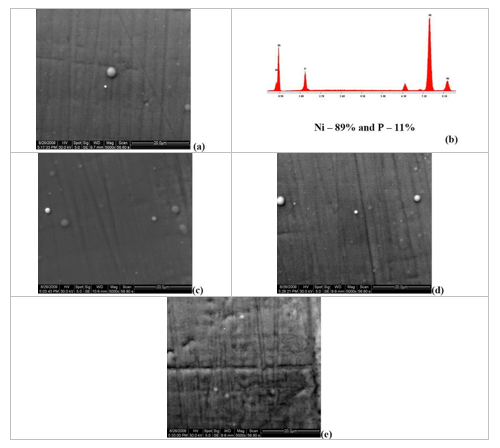
Nanostructured composite coatings offer physical and mechanical property advantages over conventional metals. The most important change resulting from a reduction of grain size to the nanometer level is the increase in the ductility, strength and hardness. Figure 2 shows the scanning electron microscope image and EDAX analysis of Ni-P coating prepared using a current density of 15 mA/cm2 which showed a composition 89% nickel and 11% phosphorus. For comparison, other Ni-P deposits prepared at 10, 12 and 20 mA/cm2 are shown in the figure. As can be seen from the SEM images, the surface is very uniform, dense and smooth with no blisters arising from hydrogen evolution are noticed for the Ni-P deposit prepared at 15 mA/cm2. On the other hand, the Ni-P deposit prepared at 20 mA/cm2 showed rough and non-uniform surfaces due to excess hydrogen evolution during deposition. The Ni-P deposits prepared at 10 and 12 mA/cm2 showed a smooth surface but the deposition rate was less than 10 µm/hr and were not considered for further characterization.
 
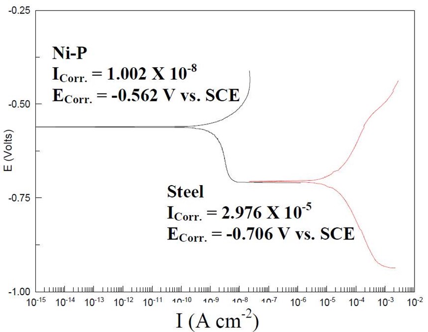
Figure 3 shows the Tafel plots of bare and Ni-P coated steel samples.  The corrosion characteristics and Vickers hardness numbers (VHN) of both the samples are given in Table 2.  As can be seen from the table, Ni-P showed three orders of magnitude lower corrosion current (1.002×10⁻⁸ A/cm2) when compared to the bare steel substrate (2.976×10⁻⁵ A/cm2).  The Stern-Geary relationship was used to calculate the corrosion rate of Ni-P (0.0044 mpy) and bare steel (13.57 mpy).  The Vickers hardness test was performed on a 3-µm thick coating which was not subjected to further heat treatment.  The VHN for Ni-P (HV100 = 173) was higher than that of bare steel (HV100 = 141).
 
Table 2 - Properties of bare steel and Ni-P coatings.
 

Coating

Corrosion potential

(VSCE)

Corrosion current density

(A/cm2)

Corrosion rate

(mpy)

Hardness

(HV100)

Steel

-0.706

2.97 × 10⁻⁵

13.57

141

Ni-P

-0.562

1.002 × 10⁻⁸

0.0044

173


Conclusion
 
Dense and uniform Ni-P coatings containing 7 to 11% phosphorus were successfully deposited onto low carbon steel by a DC electroplating process using acid electrolytes. Corrosion studies in 0.5M boric acid + 0.5M sodium sulfate solution indicated that the coatings have superior corrosion resistance.
 
Studies on Ni-B coatings

Experimental

Preparation of Ni-B coating
 
Ni-B coatings were prepared using an acidic electrolyte (pH=2.0) containing nickel sulfate, nickel chloride, sodium borohydride and sodium citrate. The bath composition is given in Table 3. Prior to plating, the carbon steel surface (low carbon, Q-Panel, 25 cm2) was polished using #600 and #1800 sand papers until a mirror finish was obtained. The surface was then cleaned with soap solution followed by rinsing in tap water. Finally, the steel samples were pickled in 10% HCl solution for 1 min followed by rinsing in running tap water and DI water. The specimen was then carefully introduced into the plating solution. The deposition was carried out galvanostatically using a potentiostat at 60°C. The deposition current density was varied from 10 to 20 mA/cm2.
 

Table 3 - Electroplating bath composition for preparing Ni-B deposits.


Bath constituents

Ni-P

NiSO4•6H2O

NiCl2

Sodium borohydride

Citric acid

pH

Temperature (°C)

Current density (mA/cm2)

75 - 165 g/L

28 -52 g/L

6.8 - 9.2 g/L

115 - 125 g/L

2.0

60 ± 5

10 - 20


Physical and electrochemical characterization
The surface morphology was studied using scanning electron microscope (SEM, ESEM Quanta FEI 200). A variety of electrochemical techniques such as linear polarization and Tafel polarization were used to evaluate the barrier resistance properties of the coating. The coating thickness was kept constant at 3.0 µm for all the electrochemical characterization studies. The electrochemical characterization was done using an EG&G PAR model 273A potentiostat / galvanostat interfaced with a computer and a three-electrode setup in 0.5M sodium sulfate and 0.5M boric acid (pH=7) solution. The steel substrate with the coating was used as the working electrode and a platinum mesh was used as the counter electrode. A saturated calomel electrode (SCE) was used as the reference electrode. All potentials in this study are referenced to the SCE.
 
Results and discussion
 
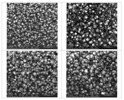
Figure 5 shows the SEM images of Ni-B deposits prepared at current densities of 10, 12, 15 and 20 mA/cm2. As can be seen from the images, the deposits are compact and dense and the grain size increased with increasing current density. Low magnification images (not shown here) did not show any cracks on the surface. The composition of the Ni-B deposits could not be determined using x-ray fluorescence or energy dispersive analysis of x-rays, as these instruments are only capable of determining elements whose atomic weights are six or higher. However, the Vickers hardness values with current density, confirming that the deposit contains boron. The VHN for the deposit prepared at 10 mA/cm2 is 615 and it increased to 728 at a current density of 20 mA/cm2. Both values are higher than those of electroless deposited Ni-P coatings (VHN = 450-600).
 
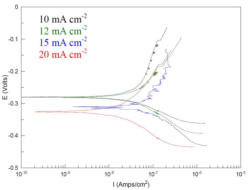
Figure 6 shows the Tafel polarization of the Ni-B coatings prepared using different current densities. The Ecorr value of the Ni-B deposit prepared using a current density of 10 mA/cm2 is ­0.280 VSCE which confirms that the deposit contains predominantly nickel. The potential shifted to more negative values as the deposition current density increased, which shows that the deposit has other elements such as boron, which affects the Ecorr. Similarly, the corrosion current also increased as the deposition current density increased. The Ni-B deposit prepared using 20 mA/cm2 showed Icorr = 8.21×10⁻⁷ A/cm2. The linear polarization results show that the polarization resistance of the Ni-B deposits increases with increasing current density. The polarization results tabulated in Table 4 indicate that these deposits possess higher corrosion resistance under industrial exposure conditions such as the one simulated in this study.
 
Table 4 - Tafel and LP characteristics of Ni-B coatings.
 
Ni-B
LP
(Ω/cm2)
Icorr
(A/cm2)
Ecorr
(VSCE)
Βa
(mV)
Βc
(mV)
10 mA
1.24×10⁵
1.31×10⁻⁸
-0.280
163.45
77.49
12 mA
3.71×10⁵
2.10×10⁻⁸
-0.281
168.05
94.258
15 mA
4.94×10⁵
6.54×10⁻⁷
-0.310
227.2
110.2
20 mA
8.77×10⁵
8.21×10⁻⁷
-0.325
194.71
84.54
 
 
Conclusion
 
In this study, Ni-B coatings were prepared using acidic electrolyte containing nickel salts and sodium borohydride as nickel and boron sources.  Vickers hardness measurements and polarization studies indicated that the hardness and corrosion resistance increased, respectively, as the deposition current density increased.  It is assumed that the increase in both the hardness and corrosion resistance by increasing the deposition current density is because of the inclusion of boron in the deposit.  Further studies such as atomic absorption spectroscopy or inductively-coupled plasma / atomic emission spectroscopy are needed in order to confirm the presence of boron in the deposit.
 
Studies on alkaline Zn-Ni and Zn-Ni-SiO2 coatings

Experimental

Preparation of alkaline Zn-Ni deposits
 
The electrodeposition of Zn-Ni was carried out on 6” × 3” steel plates obtained from Q-panels.  Before electrodeposition, the steel surface was mechanically polished using #500 and #1500 sandpapers followed by cleaning with soap solution.  The polished surface was pickled in 10 vol% hydrochloric acid for 60 sec and rinsed with de-ionized water prior to plating.
 
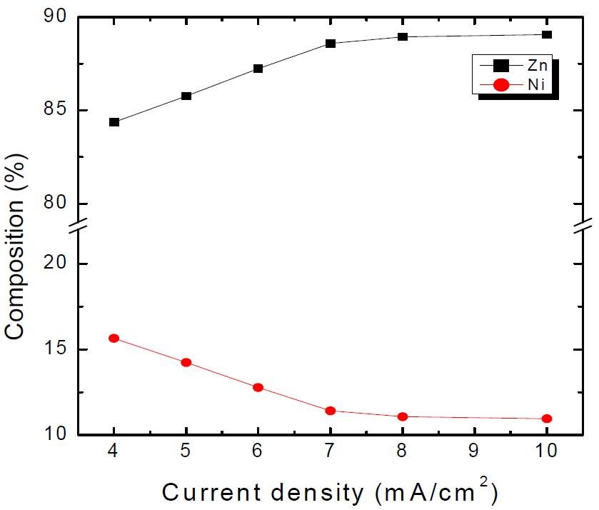
Zn-Ni coated steel panels were prepared using an alkaline bath consisting of respective sulfate salts of zinc and nickel metals and additives (pH 9.3 - 9.5) at room temperature.  The composition of the bath and plating conditions are presented in Table 5.  Ammonium hydroxide was used to adjust the pH of the bath and as a complexing agent to prevent the precipitation of metal ions as hydroxides.  The plating current density was varied from 4 to 10 mA/cm2 in order to prepare Zn-Ni alloy deposits containing 87% Zn and 13% Ni.
 
Table 5 - Bath composition for alkaline Zn-Ni deposition.
 
Ingredients
Concentration (g/L)
NiSO4•6H2O
120
ZnSO4•7H2O
180
Additive 1
160
Additive 2
60
NH4OH (28%)
~200 mL
pH
9.3 - 9.5
Temperature
RT
 
 
Preparation of Zn-Ni-SiO2 coatings
 
The Zn-Ni deposited steel panels were cleaned with soap solution and dried.  The panels were then immersed in a solution containing nickel chloride, nickel sulfate and other additives (nickel strike solution).  The effect of immersion time on the corrosion resistance of silicate coatings was studied by immersing the Zn-Ni coated panels in the nickel strike solution for different time durations from 1.0 to 5.0 min.  The silica passivation coating was applied on the surface modified Zn-Ni deposits by immersing the panels in 1:3 sodium silicate solution**.  The silica passivation temperature (75°C), time (15 min) and the concentration (1:3 water:sodium silicate) of the silica passivation process were optimized in our earlier studies.  After 15 min of immersion, the samples were slowly taken out and dried in air for 24 hr followed by heat-treatment at 120°C for 2 hr in an air oven.


**PQ® Sodium Silicates, PQ Corporation, Malvern, PA


Material characterization and evaluation of mechanical properties
 
Energy dispersive analysis using x-rays (EDAX) was used to analyze the distribution of the elements in the Zn-Ni deposits.  To ensure accuracy of the element distributions, EDAX was done at several points on the surface of the substrate.  The accuracy of the measurements for the equipment used was rated at ±0.1 wt%.  The surface morphology and the microstructure of the coating were analyzed using scanning electron microscopy by means of ESEM FEI Quanta 200 scanning electron microscope coupled with EDAX.  A Vickers hardness (HV100) indenter (Buehler Micromet 1 Microhardness Tester) was used to indent the prepared Zn-Ni-SiO2 coatings with a diamond tip.
 
Electrochemical characterization and salt spray testing
 
A variety of electrochemical techniques such as potentiodynamic polarization and open circuit potential measurement were used to evaluate the barrier resistance properties of the coating.  The electrochemical characterization was done using an EG&G PAR model 273A potentiostat / galvanostat interfaced with a computer and a three-electrode setup in 3.5% NaCl solution.  The steel substrate with the coating was used as the working electrode and a platinum mesh was used as the counter electrode.
 
Results and discussions
 
Preparation of alkaline Zn-Ni coatings
 
Figure 7 shows the effect of applied current density on the zinc and nickel content in the deposit.  As can be seen from the figure, the zinc content in the deposit increased with increasing current density.  At 6.0 mA/cm2, the deposit composition is found to be 86.83% Zn and 13.18% Ni.  This composition was selected for the preparation of the Zn-Ni/SiO2 coatings, since it has been reported that Zn-Ni alloys with 12-14 wt% Ni exhibit the best corrosion properties.
 
Preparation of Zn-Ni/SiO2 coatings
 
The surface modification process earlier developed in our laboratory was used prior to the silica passivation process.  Briefly, when zinc or Zn-Ni plates are immersed in Ni+2 containing solution, zinc displacement takes place according to the following reaction:
 
Ni+2 + Zn → Zn+2 + Ni                                                                        (1)
 
Apart from reaction (1), hydrogen evolution was also observed, enhanced by the decrease of the hydrogen overpotential on the nickel-rich surface:
 
2H+ + 2e- → H2                                                                                    (2)
 
According to the literature, besides the zinc displacement reaction, zinc-oxygen compounds are also formed according to the following reaction:
 
Zn + 2H2O → ZnO2-2 + 4H+ + 2e-                                                      (3)
 
and these zincate ions are helpful in forming the zinc silicate during immersion in sodium silicate for silica deposition.
 
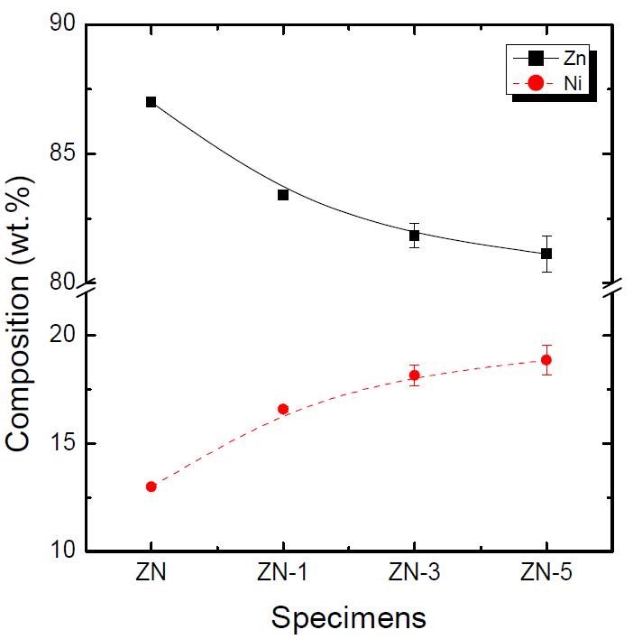
Figure 8 shows the EDAX analysis of Zn-Ni deposits immersed in the surface modifier solution for different process times.  As shown in the figure, the amount of nickel increases with increasing immersion time because of the displacement reaction between zinc in the deposit and nickel in the surface modifier solution.  Moreover, the surface is roughened as discussed below.
 
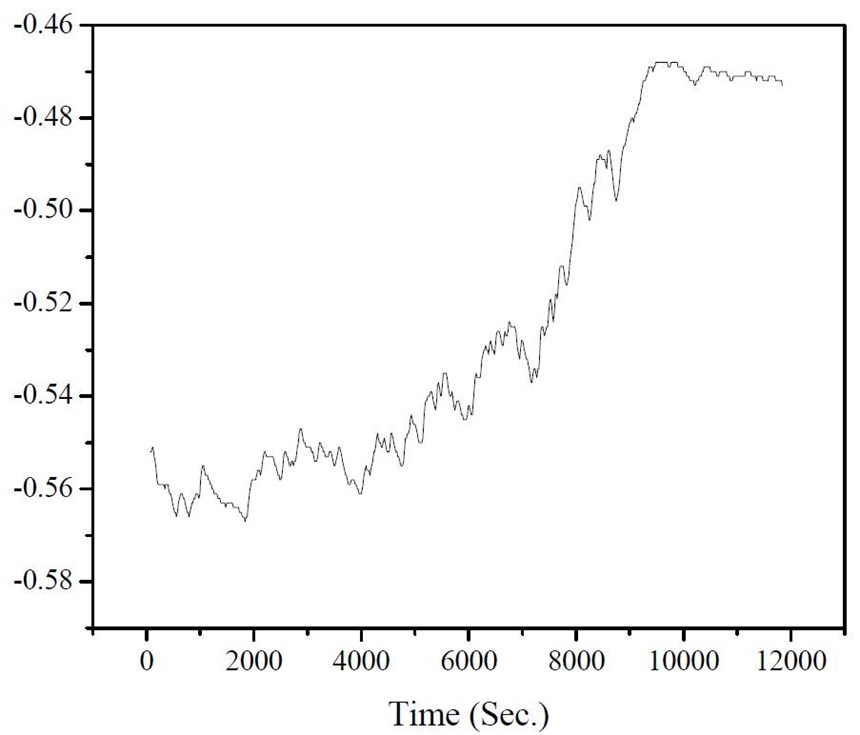
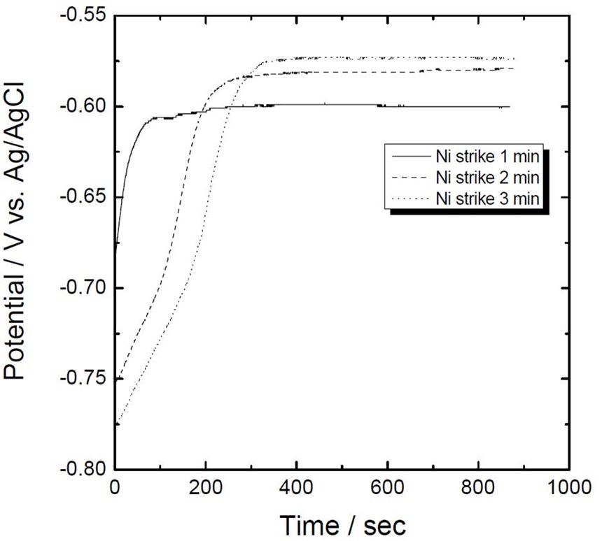
Figure 9 represents the change in the rest potential of surface modified Zn-Ni deposited plates during immersion in the silica bath.  In this experiment, the samples were immersed in the surface modifier solution for 1.0, 2.0, and 3.0 min before immersion in the silicate solution.  All samples showed similar behavior in potential variation with time during immersion in the sodium silicate solution.  That is, the potential shifted in the positive direction and remained constant until the completion of the experiment. 
 
It is interesting to note however, that there are some differences in the initial and final potential values and the time to reach stable potential values with respect to immersion in surface modifier solution.  The initial potential is more negative and the final potential is more positive when the immersion time in surface modifier solution was increased from 1.0 to 3.0 min.  In addition, the potentials were stabilized after 120 sec for the 1.0-min nickel strike sample and 350 sec for the 3.0-min nickel strike sample. 
 
This behavior can be explained as follows. During immersion in surface modifier solution, zinc from the deposit dissolves and is replaced with nickel.  It is presumed that not all the dissolved zinc was replaced with nickel and some zinc or Zn+2 or the ZnO2-2 remains on the surface, making the initial potential more and more negative when the immersion time in the surface modifier solution was increased.  Also, a more positive final potential is related to the reaction of ZnO2-2 species with polymeric silica, which forms more dense silicate layers.  Therefore, it can be concluded that a surface modification process greater than 1.0 min is important for the effective formation of silicate/silica layers.
 
Table 6 shows the composition analysis (EDAX) of Zn-Ni-SiO2 deposits that were subjected to activation for different times prior to the silica passivation process.  As shown in the table, the silicon content is higher for the 1.0-min activated sample than those activated for 3.0 and 5.0 min.  The results can be explained by taking into account that the 1.0-min activation did not produce a sufficient amount of zincate anions to be reacted with the polymeric silica species.  Thus, the silica coating on this sample is a physically bonded thick paint-like film.  On the other hand, the 3.0-min activated sample showed 20 wt% Si, 13 wt% Ni and ~49 wt% Zn in the deposit via the formation of zincate anions which are then reacted with the polymeric silica species to form metal silicates. The 5.0-min activation was disregarded since it produced a Zn-Ni surface with cracks.
 
Figure 10 shows the SEM surface morphologies of samples activated with different nickel strike times (1.0, 3.0 and 5.0 min) after silica passivation.  The formation of a silica layer is observed on the underlying Zn-Ni deposits.  As shown in the figure, a 5.0-min nickel strike treated sample exhibits cracks on the surface.  Our results indicated that rapid corrosion of the underlying Zn-Ni layer occurs by water entering into the crack.  Accordingly, it was necessary in this study to optimize the time for the nickel strike activation process.  Nearly crack-free deposits were obtained when the nickel strike conditioning time was optimized between one and three minutes.  The Vickers hardness measurement indicated that the silica passivation did not alter the hardness value of the base Zn-Ni coating.  The hardness values (HV100) calculated for cadmium, Zn-Ni and Zn-Ni-SiO2 were 55.92, 325.53 and 315.4, respectively.
 
Figure 11 shows the cross-sectional view of Zn-Ni coatings after silica deposition.  As can be seen from the figure, the Zn-Ni layer is approximately 12 µm thick (Fig. 11a) and the surface becomes rough after immersion in the surface modifier solution due to zinc dissolution and its subsequent displacement by nickel (Fig. 11b).  This rough surface helps to form an adherent, dense and uniform silicate layer of approximately 1.0 µm thick on the Zn-Ni deposit (Fig. 11c).
 
Electrochemical properties

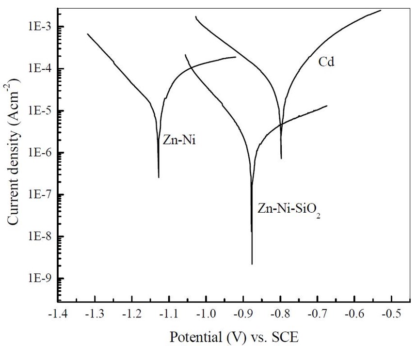
Figure 12 shows the Tafel polarization curves of cadmium, alkaline Zn-Ni and Zn-Ni-SiO2 samples in a 5% NaCl solution.  The results obtained by Tafel extrapolation method, as well as the corrosion current and deposit hardness are summarized in Table 6.  The corrosion potential of cadmium, Zn-Ni and Zn-Ni-SiO2 are -0.806, -1.127 and -0.822 VSCE, respectively.  It should be noted here that the corrosion potential of Zn-Ni after silica passivation has been shifted to a more positive value and is close to that of cadmium coatings, thereby reducing the driving force for rapid corrosion.  Also, the corrosion current of the base Zn-Ni (Icorr = 2.17×10⁻⁵) is reduced by two orders of magnitude after silica passivation (Icorr = 3.36×10⁻⁷).  These results indicated that the corrosion resistance of Zn-Ni coatings is greatly improved by silica passivation processes.

Table 6
-    Corrosion potential, corrosion current density and Vickers hardness of different samples.
 
 
Corrosion potential, ECorr (VSCE)
Corrosion current density, ICorr(A/cm2)
Vickers hardness
(HV100)
Cd
-0.806
3.28×10⁻⁶
55.92
Zn-Ni
-1.127
2.17×10⁻⁵
325.53
Zn-Ni-SiO2
-0.822
3.66×10⁻⁷
315.
 
 
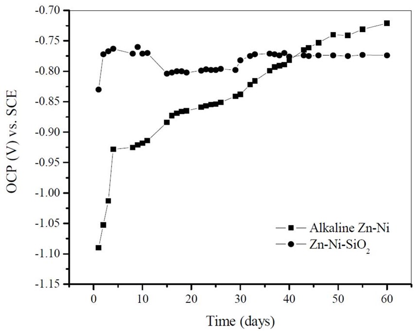
Figure 13 shows the open circuit potential (OCP) measured as a function of time for Zn-Ni and Zn-Ni-SiO2 samples immersed in 5% NaCl solution.  As can be seen from the figure, the OCP of Zn-Ni deposit starts to approach more positive values after ~15 days immersion time and reaches -0.782 VSCE after 40 days immersion.  The open circuit potential of Zn-Ni-SiO2 remains constant at -0.770 VSCE throughout the immersion period.  The initial fluctuation in the potential can be attributed to the dissolution of soluble silica present on the surface in the test solution.  The OCP measurement studies indicate that the silica passivation layer offers good corrosion protection to the underlying Zn-Ni deposit.


Conclusion

An environmentally-benign silica passivation process was developed for alkaline Zn-Ni deposits.  It was shown that a thin silicate layer can be deposited on the Zn-Ni by the in-house developed surface modification procedure followed by immersion in sodium silicate solution.  Corrosion studies in 5% NaCl indicated enhanced corrosion protection when compared to the bare Zn-Ni coatings.

 
ASTM B117 salt spray and hydrogen permeation characteristics of Zn-Ni-SiO2 coatings

Experimental
Salt spray test and evaluation of hydrogen permeation using the Devanathan-Stachurski technique
 
ASTM B117 salt spray test was performed using an Atotech Model P22E001 environmental test chamber to evaluate the first grey and red rust formation times.
 
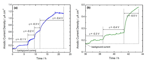
The rate of hydrogen permeation through membranes was measured continuously as a function of time using the Devanathan-Stachurski permeation cell.39 The hydrogen permeation cell setup consists of two working compartments namely, cathodic and anodic chambers.  The membrane is placed between the two chambers.  To avoid possible passivation, the anodic side of the membrane was electrodeposited with a thin layer (~0.15-0.20 μm) of palladium prior to fitting into the permeation cell.  The palladium-plated side faces the anodic side and the deposited film to be tested faces the cathodic side.  Permeation studies were done using a bi-potentiostat connected to each side.  Platinum mesh was used as a counter electrode and the membrane was used as a bipolar working electrode.  Saturated calomel electrode (SCE) and mercuric oxide (Hg-HgO) reference electrodes were used for the cathodic and anodic sides respectively.  The anodic compartment was filled with a 0.2M NaOH solution and potential was kept at –0.3V with respect to the Hg/HgO reference electrode until the background current was reduced to below 1.0 μA/cm2, which corresponds to a nearly zero concentration of absorbed atomic hydrogen on the surface.  Once the background current decreased to a very low value, the cathodic compartment was then filled with a supporting electrolyte containing 0.5M Na2SO4 and 0.5M H3BO3 buffer solution (pH=7) and the permeation experiments were stared immediately.  Nitrogen was purged on both sides throughout the experiment in order to remove dissolved oxygen from the electrolytes.  The open circuit potential of the membrane on the cathodic side of the cell was measured and then polarized potentiostatically to create conditions for hydrogen evolution.  Hydrogen generated on the cathodic side permeates through the membrane and is oxidized on the anodic surface of the membrane.  The steady state currents associated with anodic (permeation current) and cathodic (charging current) reactions were monitored continuously as the overpotential of hydrogen evolution reaction at the cathode side changed.
 
Results and discussion
 
Salt spray testing was performed in a neutral salt spray chamber to evaluate the coating performance under accelerated corrosion conditions.  The temperature in the chamber was set at 35°C with a tower temperature of 49°C.  The samples were exposed to a constant 5% salt fog in accordance with the ASTM B117 specifications.  The appearance of white rust, red rust and the failure of the samples were observed as a function of time.  Five percent of red rust on the surface of the samples was defined as the basis for failure.  The deposit thickness was ~12 µm for both Zn-Ni and Zn-Ni-SiO2 coatings.  Visual observations such as white/red rust spot formation were made after removing and examining the panels at regular intervals (usually every 24 hr).  Prior to visual observation, the test panels were washed with cold water and dried under flowing air.  Also, the cross-sectional observation of Zn-Ni-SiO2 samples was performed after the 1st, 3rd, 5th and 8th weeks of exposure.
 
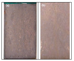
The first white rust formation was noticed after 96 and 240 hr for the bare alkaline Zn-Ni and Zn-Ni-SiO2, deposits respectively.  The white rust formation can be attributed to zinc dissolution from the Zn-Ni and soluble silica from the Zn-Ni-SiO2 deposits.  The first red rust spots were noticed after 40 days in the case of Zn-Ni while the Zn-Ni-SiO2 showed no red rust over 50 days.  The photographs of Zn-Ni (unscribed sample) and Zn-Ni-SiO2 (scribed sample) after 46 and 50 days, respectively, are shown in Fig. 14.  As can be seen from the figure, the un-scribed Zn-Ni sample showed red rust in the edges and no red rust was seen through the scribed portion of the Zn-Ni-SiO2 sample.

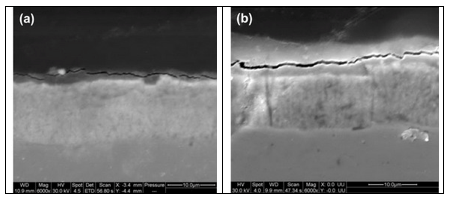
The cross-sectional analysis of the Zn-Ni-SiO2 samples after the 3rd and 7th week of testing is shown in Fig. 15. As shown in the figure, the underlying Zn-Ni deposit is unaffected for the entire exposure period. ASTM B 117 results confirmed that the silica passivation is an effective method to increase the life of the Zn-Ni coatings.

Evaluation of hydrogen permeation characteristics
 
The hydrogen permeation characteristics of alkaline Zn-Ni and Zn-Ni-SiO2 were evaluated in a buffer solution consisting of 0.5M sodium sulfate and 0.5M boric acid. Also, the hydrogen permeation properties of bare steel substrate and commercial cadmium were studied for a better understanding of the developed coatings. Different cathodic overpotentials were applied to vary the permeation currents through the membrane. Prior to any application of overpotential to the cathodic side of the bipolar electrode, the background current on the anodic side was allowed to stabilize below 0.5 mA/cm2. Subsequently, the cathodic side of the membrane was polarized in the negative direction so as to provide conditions for hydrogen evolution. Hydrogen that comes out of the anodic side after a series of adsorption-absorption-diffusion steps is oxidized potentiostatically to obtain the permeation current. The hydrogen oxidation potential in 0.2M NaOH (pH=13.0) is –1.693 VHg/HgO (-0.767 VSHE). Hence applying a potential of –0.3 VHg/HgO to the anodic side of the bipolar electrode ensured the instantaneous oxidation of the permeating hydrogen. The steady-state permeation current for each value of applied cathodic potential was noted. Using the same process, the hydrogen evolution and permeation currents of the Zn-Ni and Zn-Ni-SiO2-coated membranes were measured for each value of the applied overpotential. In our earlier studies, different corrosion protection coatings were developed and their hydrogen permeation characteristics were studied using the same experimental procedure.
 
Figure 16 shows the variation in the hydrogen permeation currents of alkaline Zn-Ni and Zn-Ni-SiO2 coatings as a function of different applied cathodic overpotential. During start-up, the background current on the anodic side (palladium-coated) was allowed to stabilize below l.0 µA/cm2. Following this, the cathodic side of the membrane was polarized in the negative direction to provide conditions for hydrogen evolution. Hydrogen that comes out of the anodic side is oxidized potentiostatically in order to obtain the permeation current. The steady-state permeation current for each value of applied cathodic potential was noted.  It was noticed that the permeation current was high in the case of Zn-Ni at all given overpotential values. It should be noted that the alkaline Zn-Ni showed permeation current density at lower overpotentials (η = 100 mVSCE) after 2 hr while the Zn-Ni-SiO2 showed no permeation current at lower overpotentials. Permeation current densities of 0.62 and 0.21 µA/cm2 were observed for Zn-Ni and Zn-Ni-SiO2 coatings, respectively, at an overpotential value of 300 mVSCE. However, in the case of Zn-Ni-SiO2, the permeation current was observed only after 36 hr when an overpotential of 300 mVSCE was applied. The permeation current density increased to 1.18 and 0.25 µA/cm2 for Zn-Ni and Zn-Ni-SiO2, respectively, when the overpotential was increased to 400 mVSCE, implying that the Zn-Ni-SiO2 coating is more resistant to hydrogen permeation than the Zn-Ni coating. The hydrogen permeation results indicated that the silica passivation method developed in this study possesses good hydrogen permeation characteristics and inhibits hydrogen entry into the steel at all applied cathodic overpotentials.
 
Conclusion

An environmentally benign silica passivation process was developed for alkaline Zn-Ni deposits. ASTM B117 salt spray test results indicated red rust formation after 40 days of exposure for the unscribed Zn-Ni coated sample and no red rust was seen through the scribe after 60 days of exposure in the case of Zn-Ni-SiO2 coated sample. The ASTM B 117 salt spray test confirmed that the silica passivation improved the corrosion properties of Zn-Ni deposits. Hydrogen permeation studies of Zn-Ni-SiO2 showed lower hydrogen permeation current when compared to the bare alkaline Zn-Ni coating at all the applied cathodic overpotentials.

References
1.      L. Wang, et al., Surf. Coat. Technol., 200 (12-13), 3719 (2006).
2.      L. Wang, et al., Appl. Surf. Sci., 252 (20), 7361 (2006).
3.      K.H. Lee, D. Cheng & S.C. Kwon, Electrochim. Acta, 50 (23), 4538 (2005).
4.      K. Krishnaveni, T.S.N. Sankara Narayanan & S.K. Seshadri, Mater. Chem. Phys., 99 (2-3), 300 (2006).
5.      Anna Gajewska-Midzialek, et al., Tribol. Int., 39 (8), 763 (2006).
6.      S.K. Kim & H.J. Yoo, Surf. Coat. Technol., 108-109, 564 (1998).
7.      I. Garcia, J. Fransaer & J.P. Celis, Surf. Coat. Technol., 148 (2-3), 171 (2001).
8.      K.H. Hou, et al., Wear, 253 (9-10), 994 (2002).
9.      H. Wang, S. Yao & S. Matsumura, J. Mat. Process. Tech., 145 (2004) 299-302.
10.      A.A. Aal, K.M. Ibrahim & Z.A. Hamid, Wear, 260 (9-10), 1070 (2006).
11.      Y. Zhou, H. Zhang & B. Qian, Appl. Surf. Sci., 253 (20), 8335 (2007).
12.      M. R. Vaezi, S. K. Sadrnezhaad & L. Nikzad, Colloid Surf. A: Physicochem. Eng. Aspects, 315 (1-3), 176 (2008).
13.      L. Shi, et al., Appl. Surf. Sci., 252 (10), 3591 (2006).
14.      M. Surender, B. Basu & R. Balasubramaniam, Tribol. Int., 37 (9), 743 (2004).
15.      K.R. Sriraman, S.G.S. Raman & S.K. Seshadri, Mater. Sci. Eng. A, 418 (1-2), 303 (2006).
16.      L. Chen, et al., Surf. Coat. Technol., 201 (3-4), 599 (2006).
17.      Bin Wu, et al., Surf. Coat. Technol., 201 (16-17), 6933 (2007).
18.      M. Gavrila, et al., Surf. Coat. Technol., 123 (2-3), 164 (2000).
19.      M.H. Sohi & M. Jalali, J. Mater. Process. Technol., 138 (1-3), 63 (2003).
20.      M.L.A.D. Mertens, Met. Finish., 96 (5), 10 (1998).
21.      M. Nikiforov, MRS Bull., 28, 157 (2003).
22.      S. Dalbin, et al., Surf. Coat. Technol., 194 (2-3), 363 (2005).
23.      C.J. Brinkner & G.W. Scherer, Sol-Gel Science: The Physics and Chemistry of Sol-Gel Processing, Academic Press, San Diego, London (1990); p. 838.
24.      M. Atik, et al., J. Mater. Sci. Lett., 13 (15), 1081 (1994).
25.      D.P. Donohue & G.T. Simpson, Proc. 13th Annual U.S. Navy and Industry Corrosion Technology Exchange, 14-17 July 2003, Louisville, USA, 2003; p. R 3001.
26.      B. Veeraraghavan, et al., Surf. Coat. Technol., 167 (1), 41 (2003).
27.      B. Veeraraghavan, et al., Electrochem. Solid-State Lett., 6 (2), B4 (2003).
28.      S.P. Kumaraguru, B. Veeraraghavan & B.N. Popov, J. Electrochem. Soc., 153 (7), B253 (2006).
29.      P. Ganesan, et al., J. Appl. Surf. Finish., 2 (1), 20 (2007).
30.      J.J. Hahn, et al., Surf. Coat. Technol., 108-109, 403 (1998).
31.      M. Hara, et al., Surf. Coat. Technol., 169-170, 679(2003).
32.      L.A. Garcia-Cerda, et al., Mater. Lett., 56 (4), 450 (2002).
33.      G.P. Thim, et al., J. Non-Cryst. Solids, 273 (1-3), 124 (2000).
34.      M.F.M. Zwinkels, et al., J. Mater. Sci., 31 (23), 6345 (1996).
35.      K. Aramaki, Corros. Sci., 43 (3), 591 (2001).
36.      K. Aramaki, Corros. Sci., 44 (6), 1375 (2002).
37.      S. Dalbin, et al., Surf. Coat. Technol., 194 (2-3), 363 (2005).
38.      K. Aramaki, Corros. Sci., 44 (7), 1621 (2002).
39.      M.A.V. Devanathan & Z.O.J. Stachurski, Proc. Roy. Soc. (London),A270, 90 (1962).
 
Luster-On Products
New Acid-Free Bright Nickel Process
The Finishing Industry’s Education and Networking Resource
PF Podcast
Metal Pretreatment Technology
Products Finishing 40 Under 40
Mocap Masking Caps Plugs Tapes
Products Finishing Top Shops Benchmarking Survey

Related Content

Anodizing

Plating, Anodizing Equipment for Variety of Applications

Titan Metal Fabricators Titan Metal Fabricators, Rightech Fabrications and Optimum Anode Technologies are leading suppliers of equipment for the plating and anodizing industries.

Read More
Anodizing

Plasma Electrolytic Oxidation (PEO): A High-Performance Coating for Light Metal Alloys

Plasma Electrolytic Oxidation (PEO) offers an innovative approach to high-performance coatings for light metal alloys, providing superior alternatives to traditional hard anodizing. The process transforms the surface of metals like Al, Mg and Ti into a robust oxide layer with customizable properties, tailored for demanding applications in aerospace, semiconductor, and industrial manufacturing.  

Read More
education

Looking to the Future of Finishing

Products Finishing takes a look at some of the ways the finishing industry is investing in workforce development and educational initiatives.

Read More
surfin

NASF's SUR/FIN 2023: Bringing the Surface Finishing Industry Together

SUR/FIN 2023 is an opportunity for those in the surface finishing industry to expand their knowledge, expertise and network.

Read More

Read Next

workforce development

Education Bringing Cleaning to Machining

Debuting new speakers and cleaning technology content during this half-day workshop co-located with IMTS 2024.

Read More
Parts Cleaning

A ‘Clean’ Agenda Offers Unique Presentations in Chicago

The 2024 Parts Cleaning Conference, co-located with the International Manufacturing Technology Show, includes presentations by several speakers who are new to the conference and topics that have not been covered in past editions of this event.   

Read More
Sponsored

Delivering Increased Benefits to Greenhouse Films

Baystar's Borstar technology is helping customers deliver better, more reliable production methods to greenhouse agriculture.

Read More
cfs masking