Electroplating of Zinc-Base Die Castings in a System Incorporating Dual Chromium
A NASF Technical Paper
In the CASS testing of 1961 outside door handles plated in one of six exterior die-cast plating machines equipped for the dual chromium system at the Flint, Michigan plant of the Ternstedt Division of General Motors Corporation, 97% of the handles tested presented an appearance which it is felt would be acceptable to a car owner after one year's service.
Addressing the Society of Automotive Engineers recently, C. F. Nixon stated: "The outstanding technological breakthrough in recent years in the field of decorative plating has been the development of two practical, reliable, accelerated corrosion tests. It is now possible to learn quickly and with reasonable assurance how a plated article will look after about a year of service on the outside of an automobile."1
In the CASS testing of 1961 outside door handles plated in one of six exterior die-cast plating machines equipped for the dual chromium system at the Flint, Michigan plant of the Ternstedt Division of General Motors Corporation, 97% of the handles tested presented an appearance which it is felt would be acceptable to a car owner after one year's service. Figure 1 shows the performance of Flint handles as rated in the field by the General Motors Research car survey.2 The last figures shown, while obtained before the survey was complete, represent substantial samples. The 1961 figure, for example, represents 134 handles. The 0.25 year (three months) represents an average exposure time for the model year at the time of the survey, and of course covers the winter months when most of the corrosion takes place. The agreement with the CASS test for the 1961 handles is most striking. Beyond this, however, the curves illustrate the progress that has been made in improving the quality of the plating on these parts, particularly since the introduction of dual chromium, which in this case occurred toward the end of the 1959 model year. It is the purpose of this paper to discuss the measures taken to effect this improvement.
Dual chromium plating is not simply a matter of applying two layers of chromium on a part. To apply it properly requires careful planning and close control of the chromium plating operations, and to obtain full benefit from the system particular attention must be given to the substrates. Before proceeding to discuss the chromium operations and, subsequently, certain factors pertaining to the micro-crack pattern, other aspects of our plating operations will be discussed.
General plating practices
Uniformity of current from rack to rack, and from one tank area to another is important when the maximum performance is sought. All buss and anode bar connections are therefore cast-welded at the tanks to ensure continuing good electrical conduction and current distribution. Mechanical connections in built-up machine carriers are bypassed by cables running from the brush holders to the rack-carrying members, and cast-welded at both ends. This measure has reduced the carrier current variation from 25 to less than 5%. Wherever possible, screw-type contacts are used on our racks to ensure uniformly good contact to the parts. The racks, incidentally, are made of steel below the solution level for reasons of economy. When current distribution requires it, a copper stringer may be used to supplement the steel members.
Rectangular nickel anodes are used because they present almost their original area throughout their life, when properly butted together, and therefore preserve uniform current distribution. Preservation of anode area, and maintenance of current distribution, is also aided by the practice of pumping out the copper and nickel solutions every five or six weeks for inspection and replenishment of the anodes and treatment of the solutions.
The highly stressed condition of the chromium layer, and the nature of die castings themselves, places a premium on proper cleaning, though this by no means implies that blistering is a problem. It is not. Cleaning methods are orthodox, including the use of diphase washing machines. Reverse current cleaners are used prior to copper strike and prior to nickel. All possible means are taken to avoid shorts and bipolar effects, by using only external heat exchangers on all electrified tanks.
Cyanide copper is regarded primarily as a sealer for the die castings. On this basis, plate thickness has importance, particularly when the copper is applied over parts with appreciable porosity. Air-agitated bright cyanide copper solutions are therefore used, and are based on potassium for maximum speed. Cathode current density is held to an average of 25 A/ft2, it having been found that lowered efficiencies at higher amperages resulted in a net loss in plate thickness. To avoid roughness while pressing for maximum thickness, the anodes in copper plate are bagged, and the solutions are returned to the tanks by means of weir boxes. For the same reason (prevention of roughness), copper anodes rather than steel anodes are used in the copper strike solutions. The strikes are separate from the copper plating tanks.
Since protection of the basis metal in the dual chromium system involves the intentional corrosion of the nickel, it follows that nickel thickness is a factor in determining the life of the system, particularly in terms of very extended exposure. Air-agitated, proprietary, high-chloride nickel solutions are therefore used; with the nickel chloride at thirty, the nickel sulfate at eight ounces per gallon; and operating at an average current density of 100 to 110 A/ft2.
As Lovell has shown,3 nobility of the nickel is important, and this is considered in choosing the particular brightener system used. Ductility of the nickel is also an important factor since brittle nickel will itself have a tendency to crack with consequent basis metal failure. As a side note, the nickel anodes are not bagged, but when certain precautions are observed, roughness is not a problem.
These measures are considered to constitute good plating practice under this plant's conditions of operation. They are not technically essential to the functioning of the dual chromium process, but they do assist in maintaining a sound base on which to apply the chromium, and therefore permit a fairly consistent high level of corrosion resistance.
Dual chromium plating - introductory
A detailed explanation of the dual chromium theory was presented by W. E. Lovell at the 1960 AES Convention.3 Briefly stated in simple terms, the corrosion of nickel is thought to proceed by electrolytic action between the nickel and the chromium, and it was shown that the total current flow is controlled solely by the area of the chromium; the area of nickel exposed not being a factor. If this current can be spread over a great number of points, the amount of current at any one point, and therefore the local attack on the nickel, will be correspondingly reduced. The dual chromium system establishes such a situation by cracking the chromium in a micro-pattern along innumerable lines on the surface of the plate. The nickel, of course, is anodic.
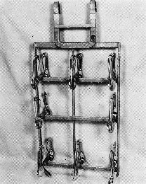
While capable of producing outstanding results, the operation of the system does require carefully detailed engineering and control if the maximum results are to be realized. This is particularly true of die castings, most of which have shapes of some degree of complexity, and this plant has been forced upon occasion to slow down machines by as much as 30%, to replace racks, and to take other measures to meet the demands of the process. The problem can perhaps be best appreciated by considering experiences, good and bad, with a comparatively simple part, and for the purpose the outside door handle is well suited. During the period about to be discussed, more than ten million handles were plated, and more than 2,500 were CASS tested. Handles racked as they are plated are shown in Fig. 2.
Production experience - O.D. handles
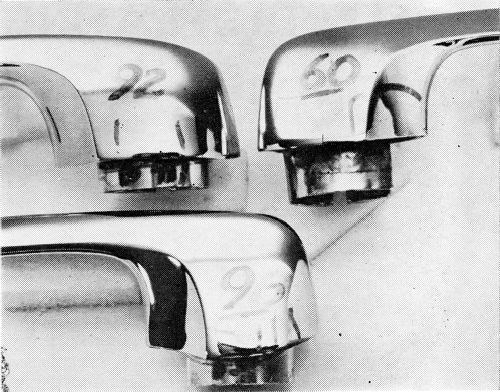
In order that the data which follows be understood, it is necessary to define the corrosion rating system employed. As developed by the Cadillac Motor Division,1 the surface of the part is divided into squares. A perfect part is rated 100, and four points are deducted from the rating for every 1% of the squares in which corrosion occurs down to a rating of 80. In the case of the O.D. handles, the significant surface of the part is divided into 200 quarter-inch squares. A rating of 100 is given a perfect handle, two points being deducted for every square in which corrosion occurs, so that a handle with a 92 rating has corrosion in four squares. As a point of reference, an ASTM rating of 8 would be regarded as being much worse than a 92 in this system. Also, a handle or other part with a rating of 92 is felt to represent a quality level which would be acceptable to a customer after a car had one year's service. The target, and in most cases the performance, is much higher. Typical ratings are illustrated in Fig. 3. It is important to note that all parts are cleaned with magnesium oxide before exposure to the CASS test. The test is therefore severe.
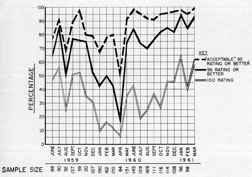
Figure 4 shows the percentages of production handles meeting various standards of performance after sixteen hours CASS test. The top line shows the percentages having a rating of 92 or better; that is, commercially acceptable. The center line shows those with no more than two spots of corrosion; that is, rated 96 or better. The bottom line shows the percentages with no corrosion. All of the data shown is for dual chromium production, though much of it, as will be seen, did not have the proper micro-crack pattern. All of the plating was done in the same plating machine.
The dual chromium operation was applied to O.D. handles beginning in early 1959, and the immediate effect was to raise the CASS performance. Self-regulating baths were used throughout in this particular machine. In the beginning the first chromium was a crack-free type; the second was a low-concentration, micro-cracking type, which it still is.
Performance fell off in August, and surging of the current was resorted to in both tanks. In this system, first developed by Guide Lamp Division, and a subject of patent application, a current higher than the normal burning point is applied. Before the metallic ion concentration can become sufficiently depleted to cause burning, the current is dropped, and this cycle is repeated as plating progresses. In this particular machine the current was held at a high for five seconds, then dropped to the low for three seconds. Some improvement in thickness resulted from this practice, particularly in low current density areas.
In September and October, performance was somewhat better, but in November a decline set in which continued for some months. During this time chromium thicknesses on failed parts were reasonably high, but the proper micro-crack pattern could not be maintained with any degree of consistency. In February additional generator capacity was added to the second chromium tank, but with no more than a slight temporary improvement.
In April, as the chart shows, performance fell to its low point, and since the difficulty appeared to lie in obtaining the micro-crack pattern, the approach was taken of supplying more of the cracking type chromium (i.e., that used in the second bath). Tests made some time before had shown that the desired micro-crack pattern and corrosion resistance could be obtained from a single, low concentration bath if sufficient time was allowed. It was therefore argued that the crack-free chromium in the first bath should be replaced with the low concentration type used in the second in order to build more stress into the deposit to favor formation of the micro-crack pattern. As a compromise, however, it was decided that this bath should be operated at a somewhat higher concentration in order to preserve covering power and throwing power. An advantage to this change also lay in the fact that both catalysts were identical, permitting the rinses to be shut off between the two baths, thus eliminating dragout losses from the first chromium plating bath. The economics and waste disposal situation were therefore highly favorable.
The first solution was therefore changed over in mid-May, starting with 35 oz. of chromic acid and about 0.14 oz. of sulfate per gallon. The result was an immediate improvement in ability to maintain the crack pattern and corrosion resistance. It was noted, however, that chromium thicknesses in low current density areas were lower. An increase in throwing power was therefore sought by manipulating the chemical composition of the bath and the operating conditions, along conventional lines. These measures were taken primarily in the first solution, but they were tried also in the second. The net result, however, was that corrosion resistance began to drop, despite some improvement in thickness. Faced with the apparent choice of obtaining the micro-crack pattern or plate thickness, the crack pattern was chosen as being most important, with the CASS test serving as a guide. The results of CASS tests since then have been gratifying, as the chart shows.
As a result of these and other parallel experiences, the first chromium solutions for die castings are now operated in the area of 35 to 40 oz. of chromic acid and 0.12 to 0.15 oz. of sulfate per gallon. The second solutions are operated at 26 to 28 oz. of chromic acid and 0.15 to 0.17 oz. of sulfate per gallon. Temperatures approximate 105 to 120°F in the first, and 125 to 135°F in the second bath. At present the time in each tank is approximately six minutes. The specific operating conditions for a given machine, including the chemical compositions of the baths, current density, surge cycle (if any), and racking arrangements can only be finalized and maintained by continuing observation of the crack pattern on the particular parts being plated, supplemented by CASS results on a substantial basis. The Ternstedt Detroit plant, for example, plates its steel parts with extremely successful results with the second self-regulating bath chromic acid at 22 oz. and sulfate at 0.11 oz./gal.
It should be emphasized that the data presented here is based on a highly critical rating system and that a 92 is still a rather good part. Further, the use of magnesium oxide, while necessary for consistency of results and good correlation with outdoor exposure,5 does seem to increase the severity of the test.
This should also be said: In certain cases, and the outside door handles are included in this group, the parts are so shaped that in the present state of knowledge, what is considered to be the best crack pattern cannot be obtained all over the part. This situation may be aggravated by the necessity of plating a mixture of parts in a machine. In such cases the parts should be considered carefully as to end use, and should be racked to present the most significant surfaces (from the standpoint of appearance and exposure to corrosive influences in service) as directly as possible to the anodes. The recesses will then develop something less than the desired micro-crack pattern, but a degree of improvement will be obtained which in most cases will result in an acceptable part. Development of the process cannot, of course, be left at this point, since increasingly high standards of corrosion resistance will necessitate finding means to obtain the desired micro-crack pattern consistently regardless of surface contour. This is currently a subject of intensive investigation.
Extended CASS exposure - O.D. handles
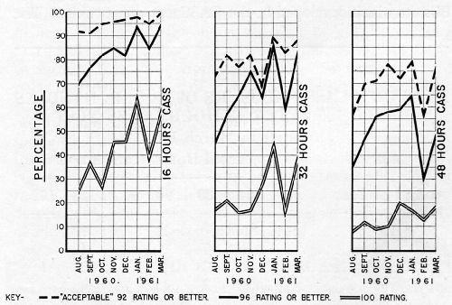
In view of the prospect of increasingly drastic requirements, a measure of performance upon prolonged exposure at the present time is in order. Figure 5 shows the CASS results for 1961 handles after 16, 32, and 48 hours, grouped as to ratings as was Fig. 4, and indicating fairly steady deterioration with continued exposure, particularly at the expense of the 100 ratings.
Prolonged exposure data for the production handles are considered from another aspect in Table 1, which compares an early period with a more recent one in terms of the deterioration of parts grouped according to rating. It is unfortunate that comparable exposures beyond 32 hours are not available, but fairly consistent improvement is shown in the figures for the later period.
Apart from its significance as an added measure of current performance, it is felt that the degree of deterioration shown here upon continued exposure is in large part the result of the necessity, at the present time, of compromising for something less than the ideal micro-crack pattern. This is given some support by the fact that small quantities of handles, plated under ideal conditions, have withstood more than 100 hours CASS exposure without failure. Indeed, as Table 2 shows, very good results have been achieved upon occasion on production handles when the desired pattern was achieved all over through some fortuitous combination of circumstances.
For the production quantities considered in these extended CASS tests, the condition of the basis metal is undoubtedly also a factor. As a general observation, it has been noted that as control of the crack pattern improved, more and more of the failures which did occur were located in the trim and parting line areas. This was particularly true of these extended exposures.
CASS performance - general
The degree of corrosion resistance achieved on other parts is dependent upon the complexity of shape, which bears upon the throwing power - micro-cracking conflict discussed, and upon the soundness of the die castings. In this connection, it is interesting to note that, as often as not, surface chills and surface porosity cause no trouble. It is when porosity in the body of the casting is exposed that difficulty with corrosion resistance is likely to be encountered.
Table 1 - Deterioration of O.D. handles with extended CASS exposure.
June 1959 through September 1959 | |||||||||
Percentage after 32 hr - Rating | Percentage after 64 hr - Rating | ||||||||
Sample size | Rating after 16 hr | 100 | 98 | 96 | Acceptable (92-100) | 100 | 98 | 96 | Acceptable (92-100) |
155 | 100 | 51% | 22% | 9% | 92% | 34% | 21% | 10% | 76% |
82 | 98 | ---- | 51% | 10% | 80% | ---- | 20% | 1% | 49% |
August 1960 through February 1961 | |||||||||
Percentage after 32 hr - Rating | Percentage after 64 hr - Rating | ||||||||
Sample size | Rating after 16 hr | 100 | 98 | 96 | Acceptable (92-100) | 100 | 98 | 96 | Acceptable (92-100) |
288 | 100 | 57% | 25% | 9% | 97% | 32% | 30% | 17% | 91% |
185 | 98 | ---- | 54% | 29% | 91% | ---- | 34% | 32% | 83% |
138 | 96 | ---- | ---- | 49% | 90% | ---- | ---- | 27% | 72% |
Table 2 - Extended CASS exposure of 32 O.D. handles rated 100 after 48-hr CASS test.
Cadillac rating at end of test | Total hours of CASS exposure | |||||
64 | 80 | 96 | 112 | 128 | 172 | |
100 | 1 | 1 | 1 | 1 | ||
98 | 8 | 7 | 1 | 1 | ||
96 | 3 | 2 | 1 | 1 | ||
92 | 2 | 1 | ||||
80 | 1 | |||||
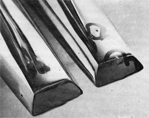
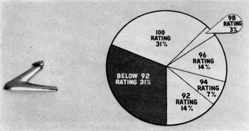
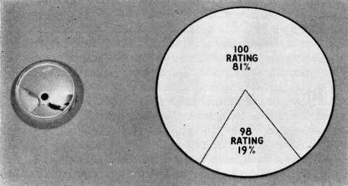
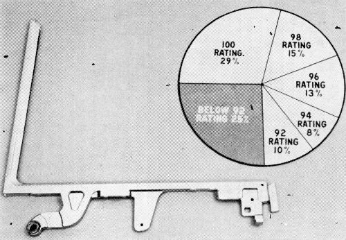
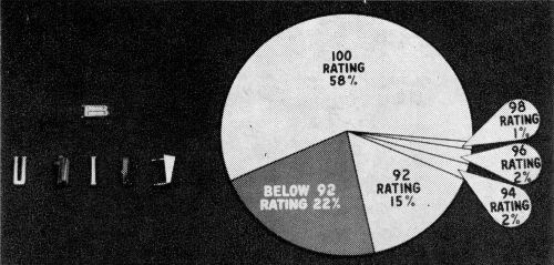
The mirror base, as Fig. 6 demonstrates, is subject at times to corrosion failure arising from porosity in a parting line. Blisters which developed in the CASS test are encircled. The other part shown has not been exposed, but shows clearly the porosity from which the corrosion arises. Only 69% of these parts met the 16-hour CASS test acceptably, as Fig. 7 shows, and it is obvious that corrective measures lay in the province of the die caster. The mirror head, however, combines a sound casting with a relatively simple shape from the plater's viewpoint. CASS results (Fig. 8), consequently, have been excellent.
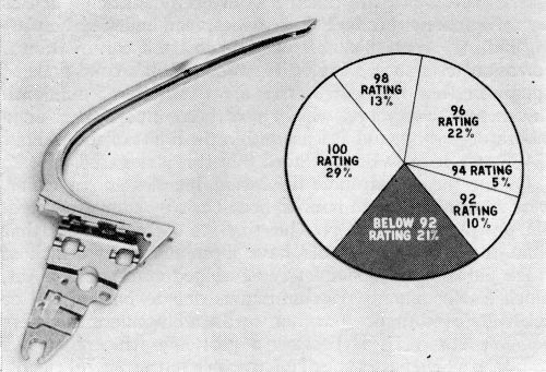
Control ventilator (C.V.) frames, though sound as to basis metal, present some degree of complexity of shape. The over-all CASS performance (Fig. 9) showed 79% of these parts in the acceptable range. The CASS rating here may be somewhat severe since the usual points of failure are shielded on the automobile, and service performance is excellent. Nevertheless, these ratings indicate what may be expected from this type of shape.
Rear window frames (Fig. 10) were 75% acceptable after CASS test. Some porosity is encountered in the rather long, thin sections involved, but the primary source of difficulty is the necessity of having one part cross another in balancing rack areas within the physical dimensions of the machine. Even a six-inch separation does not entirely eliminate the shading effect in terms of the micro-crack pattern.
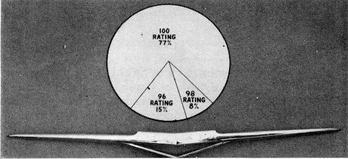
The front emblem (Fig. 11) is an excellent example of the capabilities of the dual chromium system properly applied on sound castings.
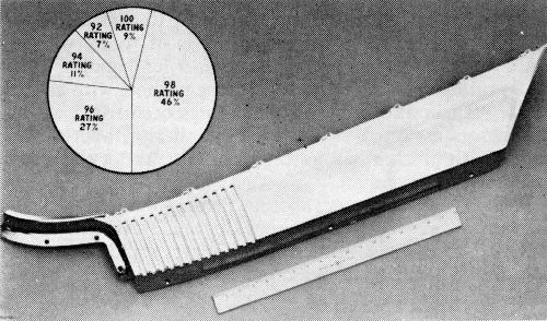
Figure 12 shows the performance for the rear wheel house molding, a rather large, but generally sound die casting. Corrosion which did occur lay in the recess of the tail section. It is interesting to note that the use of auxiliary anodes across the face of this part, in an attempt to build up chromium thickness, was disastrous to CASS performance due to gross cracking through the nickel, coupled with thin copper caused by the shading effect of the auxiliary, which was not connected in the copper tank. The performance shown does not involve the use of auxiliary anodes.
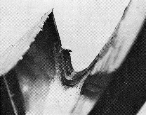
Script lettering (Fig. 13) is particularly susceptible to corrosion arising from trimmed edges, which are difficult to maintain true and clean because of the configurations involved. For the most part, at least in Ternstedt Flint operations, scoring of these edges is not a problem, nor is the break, which is quite readily sealed over. While deep recesses, particularly when they involve sharp interior corners, do cause trouble, the chief source of corrosion lies in small fragments of flash folded over, or redeposited by the trim punch. An example is shown in Fig. 14 which is a cut-away script section. This figure also shows white corrosion in the deeply recessed area.
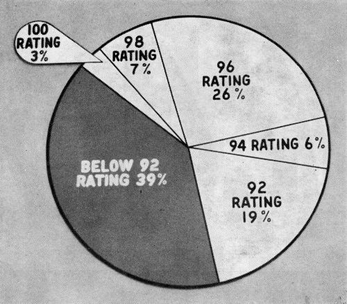
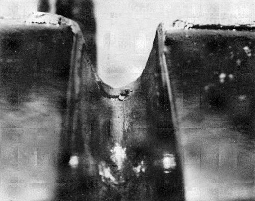
Separate letters, while subject to the same comments made regarding script, are much less seriously affected, presumably because of their simpler outlines. Figure 15 shows 78% of the parts tested to be within the acceptable range. Figure 16 again shows corrosion arising from a fragment of flash. It can be seen that the trimmed edges on the outer surfaces were sealed over by the copper and nickel. Such areas usually develop the micro-crack pattern quite readily, and corrosion there is not a problem.
This completes the portion of this paper covering the description of the process and its present record of accomplishment. A natural reaction on the part of anyone without first-hand acquaintance with the dual chromium system is to surmise that the performance claimed for some of these parts is either not true, or is actually due to increased plate thickness. As to the first, the proof is on the cars, and if our observations are correct, it will be found that service performance usually exceeds these laboratory evaluations. As to the second, it is our position that plate thickness, by itself, is not the determining factor in corrosion resistance, beyond rather obvious limits, in a copper-nickel-chromium system, despite plate thickness requirements being an important part of all current plating specifications.
Plate thickness versus CASS
Data given in the succeeding tabulations are based on the same production outside door handles previously discussed. Copper and nickel thicknesses were determined microscopically; chromium thicknesses by the hydrochloric acid drop test.6 All determinations were made in the same minimum area on the top surface of the parts. All handles with ratings below 92 were so checked, and are included in these summations. Unfortunately, data for higher ratings were lacking for most of this period, though we do have thicknesses for 92 and 94 ratings toward the end of 1960.
Table 3 summarizes all thicknesses for the variously rated parts during the period we previously discussed. There is here no clue to a relationship between the thicknesses of copper, nickel, chromium or combinations of these, with the CASS ratings. In fact, the thicknesses for handles with a CASS rating of 60 are remarkably close to those with a rating of 94. It can also be seen that failures occurred with high thicknesses as well as with low, a number of failures being noted with thicknesses as high as thirty and even forty millionths of chromium.
Table 3 - Summation of O.D. handle plate thicknesses by rating (August 1959 through December 1960).
16-hr CASS rating | No. of samples | Copper | Nickel | Chromium | ||||||
High | Low | Avg. | High | Low | Avg. | High | Low | Avg. | ||
60 | 23 | 0.00076 | 0.00020 | 0.00050 | 0.00104 | 0.00062 | 0.00077 | 0.000027 | 0.000013 | 0.000020 |
80 | 26 | 0.00085 | 0.00031 | 0.00058 | 0.00128 | 0.00042 | 0.00084 | 0.000046 | 0.000013 | 0.000028 |
84 | 63 | 0.00094 | 0.00023 | 0.00062 | 0.00129 | 0.00048 | 0.00084 | 0.000048 | 0.000011 | 0.000028 |
88 | 173 | 0.00090 | 0.00023 | 0.00060 | 0.00139 | 0.00050 | 0.00086 | 0.000058 | 0.000009 | 0.000014 |
92 | 18 | 0.00072 | 0.00021 | 0.00048 | 0.00093 | 0.00048 | 0.00076 | 0.000036 | 0.000011 | 0.000023 |
94 | 23 | 0.00080 | 0.00024 | 0.00050 | 0.00105 | 0.00064 | 0.00080 | 0.000044 | 0.000010 | 0.000020 |
With regard to copper, another factor would enter here if the parts were inherently porous, in which case the sealing effect of increasing thicknesses of copper would become important. There is good reason, based on experience, to hold copper thicknesses as high as possible, preferably 0.0006 to 0.0007 in. for the average run of parts.
As to nickel, since the system is based on the sacrificial corrosion of nickel, it is obvious that the greater the nickel thickness, the longer will be the period of basis metal protection, other things being equal. The area of nickel exposed through the chromium is also a factor, as is its nobility, but in general it may be stated that nickel thickness will become increasingly important as CASS standards are raised.
Returning briefly to Fig. 4, it will be noted that April 1960 was the worst month; November and December among the best, from the standpoint of corrosion resistance. Turning to Table 4 however, the thicknesses shown for these months, particularly in the case of chromium, might have led one to expect the reverse to be true. Further, the thicknesses shown for parts rated 92 and 94 happen to be, on the whole, lower than those for the group rated 60 to 88.
It should also be stated that these parts, as die castings, are of quite uniformly good quality from one month to another, and in our opinion quality of the castings as such is not an important factor in the performance variations noted.
The matter of plate thickness has been considered in this negative manner because of the widespread belief in the plating industry that thickness of plate in itself can guarantee corrosion resistance. Under Ternstedt Flint's conditions of operation (not considered here are the hundred millionth thicknesses, and more, which have been investigated on a laboratory basis), and at least within the limits of the 16-hour CASS test, it must be concluded that this is not true.
Table 4 - Summation of O.D. handle average plate thicknesses by month.
Copper | Nickel | Chromium | No. of samples | |
1959 | 60-88 rating after 16-hr CASS | |||
Aug. | 0.00038 | 0.00097 | 0.000029 | 25 |
Sept. | 0.00040 | 0.00106 | 0.000029 | 9 |
Oct. | 0.00057 | 0.00086 | 0.000025 | 3 |
Nov. | 0.00055 | 0.00087 | 0.000020 | 4 |
Dec. | 0.00065 | 0.00087 | 0.000028 | 23 |
1960 | ||||
Jan. | 0.00066 | 0.00090 | 0.000026 | 58 |
Feb. | 0.00063 | 0.00088 | 0.000031 | 35 |
Mar. | 0.00067 | 0.00079 | 0.000030 | 33 |
Apr. | 0.00063 | 0.00076 | 0.000030 | 38 |
May | 0.00057 | 0.00082 | 0.000032 | 12 |
June | 0.00076 | 0.00075 | 0.000024 | 2 |
July | 0.00064 | 0.00085 | 0.000024 | 7 |
Aug. | 0.00047 | 0.00068 | 0.000021 | 14 |
Sept. | 0.00057 | 0.00079 | 0.000030 | 8 |
Oct. | 0.00059 | 0.00083 | 0.000026 | 6 |
Nov. | 0.00043 | 0.00068 | 0.000019 | 4 |
Dec. | 0.00066 | 0.00071 | 0.000025 | 3 |
1960 | 92-94 rating after 16-hr CASS | |||
Oct. | 0.00048 | 0.00076 | 0.000023 | 13 |
Nov. | 0.00047 | 0.00074 | 0.000021 | 12 |
Dec. | 0.00051 | 0.00082 | 0.000028 | 16 |
During the period under discussion, handles, in particular, were scrutinized on an hour-to-hour basis by competent people, and it is therefore possible to state with assurance that what these failed parts did have in common was a lack of crack pattern, an incompletely developed crack pattern, or, much less commonly, discontinuities due to basis metal or substrate conditions. In other words, if chromium thickness has importance, it is because a particular thickness level results in a beneficial type of micro-crack pattern in the deposit, and not because there is a particular number of atoms of chromium between the nickel and the atmosphere.
At this stage of the development much remains to be learned about the conditions under which a given crack pattern will be obtained, and as has been stated previously, much depends upon the nature of the work. The thickness necessary to develop an optimum crack pattern therefore remains an area in which light can still be shed. The Ternstedt Detroit plant, however, plating steel parts, and using a conventional chromium solution followed by a micro-cracking type, has firmly established that fifty millionths is the minimum chromium thickness required to reach their optimum, though very adequate results are obtained with thirty millionths. In the Flint operation, with both baths of the micro-cracking type, there are indications that the chromium thickness required may be somewhat less.
Results of the examination of a few recently plated handles are shown in Table 5, and while the micro-crack pattern is not the optimum (It is for the most part what will later in this paper be shown designated as type M), the results are, it is felt, excellent. Chromium thicknesses are fairly low.
Table 5 - Extended CASS exposure of 8 O.D. handles plated in two low concentration cracking-type chromium baths (May 1961).
CASS rating at indicated hours | Chromium plate | |||||||
Sample No. | 16 | 32 | 48 | 64 | 80 | 96 | Cracks/in. | Thickness at minimum area (millionths) |
1 | 100 | 100 | 100 | 550 | 19 | |||
2 | 100 | 100 | 100 | 600 | 21 | |||
3 | 100 | 100 | 100 | 400 | 22 | |||
4 | 100 | 100 | 100 | 1000 | 20 | |||
5 | 100 | 100 | 100 | 100 | 1100 | 30 | ||
6 | 100 | 100 | 100 | 100 | 98 | 400 | 15 | |
7 | 100 | 100 | 100 | 100 | 100 | 92 | 800 | 18 |
8 | 100 | 100 | 100 | 98 | 900 | 17 | ||
Factors influencing the CASS - Chromium thickness relationship
It is apparent that the old rules for the operation of chromium solutions, which were adequate to produce a bright deposit approximating a specified thickness, are no longer adequate. Studies are therefore being made to determine how the CASS box would like to have chromium plated, and what kind of bath would be required to best achieve this. Very preliminary results of such a study now being undertaken by General Motors Research shed some light on certain aspects of the effect of chromium thickness, and offer a promising avenue for further exploration of the chromium plating process.
These experiments consisted of CASS testing triplicate sets of steel panels uniformly plated with conventional chromium over buffed Watts nickel to definite thicknesses. The panels used, and the control of current density distribution by means of the "half box" have been previously described in the literature.9 Details of the plating procedure are given in an appendix, since they are conventional in nature. Thicknesses were determined by x-ray fluorescence11 and interferometric12 methods. The results shown cover a total of 185 panels.
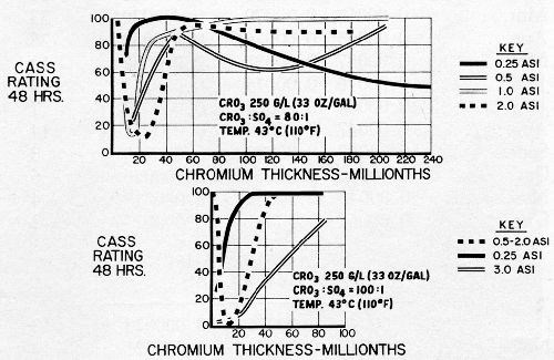
The results obtained are summarized in Fig. 17 in which average CASS ratings after 48 hours exposure are plotted against chromium thicknesses. The upper chart, for the 80:1 bath, shows that basis metal protection first decreases, with increasing chromium thickness to about 20 to 40 millionths, for current densities from 0.5 to 2.0 A/in.2 As thickness increases beyond 40 millionths, basis metal protection becomes substantially complete. The 0.25 A/in.2 curve however, shows good basis metal protection at low chromium thicknesses, and gradually deteriorates in this respect as thickness is increased. The plots shown in the lower chart for the 100:1 bath, show similar trends up to 2.0 A/in.2, though the dip in performance is deeper, and the rate of recovery for the 0.25 A/in.2 curve is much slower. The 3.0 A/in.2 curve included here, however, is quite startling. There was essentially no protection against basis metal corrosion at low chromium thicknesses, and only gradual improvement is found as chromium thickness increases.
Examination of the panels before and after CASS testing led to some interesting observations. The 0.25 A/in.2 panels from the 80:1 bath had no visible crack pattern before or after exposure, at any thickness, and basis metal attack increased in the form of rust spots as thickness increased beyond 50 millionths. Very numerous pits were found in the very low thicknesses (as many as 250,000 per square inch), it being apparent that the relatively good corrosion resistance noted was related to the nickel exposed through pores in the chromium.
Other panels up to 2.0 A/in.2 from both baths showed no physical discontinuities other than those attributable to the nickel or basis metal, in the lower thicknesses before exposure, when examined under the microscope. As the thickness increased in the area of twenty to forty millionths, widely spaced, parallel cracks were noted. These became less widely spaced as thicknesses increased, and the fine pattern reported most effective by Lovell3 appeared at thicknesses above fifty millionths. After exposure, panels in the very low thicknesses were substantially free from rust, but were dull and stained with a greenish material. Even after removal of the stain, the dullness remained, and upon microscopic examination numerous pits were found. Stripping the chromium revealed that the nickel was severely pitted.
At chromium thicknesses only slightly greater, the deposits remained bright, but there were numerous rust spots. Upon removal of the rust, relatively large, widely spaced pits were found (from one to two per square inch to perhaps one or two hundred). These thicknesses correspond to the minimum protection areas of the curves shown for both solutions. As the chromium thickness increased further, the rust spot density decreased, but unsightly gross cracks appeared. The rust spots were almost invariably located along these cracks. Brightness was not appreciably affected.
At still greater thicknesses, rust spots almost completely disappeared (those found were usually associated with nickel imperfections). There was a greyish surface stain, but upon its removal the original brightness was very nearly restored. Microscopic examination showed the presence of the desirable fine network of cracks (on the order of 500 to 1000 per inch).
Panels plated from the 100:1 solution at 3.0 A/in.2 developed parallel, widely spaced cracks associated with rust spots. While not yet adequately explored, it is surmised that these cracks possibly extended through the nickel, a condition which has been observed on some production part areas chromium plated at very high current densities.
Data on nickel runoff (i.e., nickel contained in CASS solution collected from panels during testing) confirmed the findings of Thomas, et al.9: protection of the basis metal existed where nickel in the runoff was 2 mg/ft2/hr or more, and basis metal corrosion was found where nickel in the runoff was less than this.
The results of these tests, incomplete as they are, confirm the belief that corrosion resistance in this copper-nickel-chromium system is determined by the area of nickel exposed; in the dual chromium system by the micro-cracks in the chromium. They also again show how thickness, taken by itself, can be entirely misleading. It will also be noted that pits in the chromium, if sufficiently numerous and well distributed, can provide some basis metal protection, but that marked loss of brightness and luster results.
It should be stated, also, that while the results became available too late for inclusion in this paper, tests made by Ternstedt Flint with production solutions confirm these results as to general trends in the current density/chromium thickness/CASS performance relationship.
Crack pattern terminology
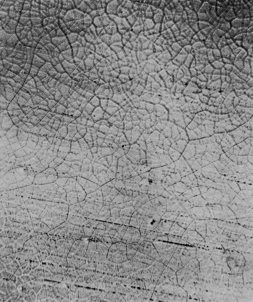
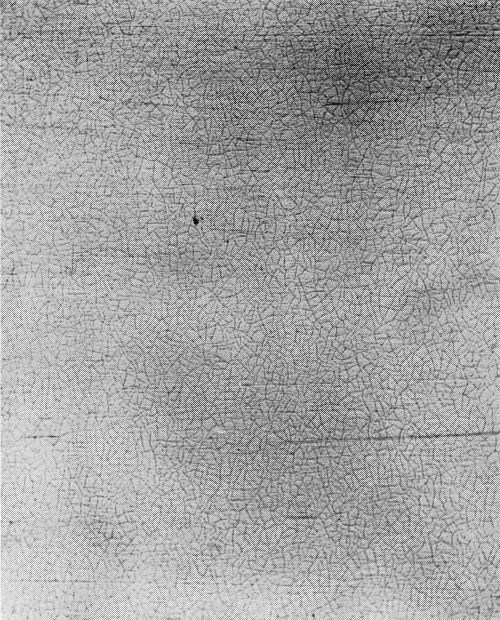
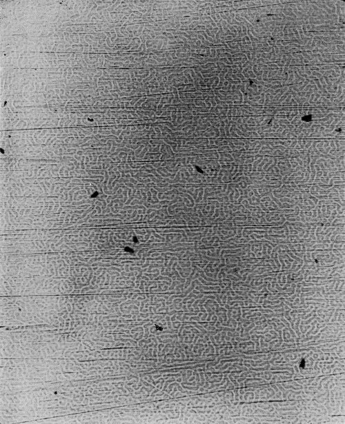
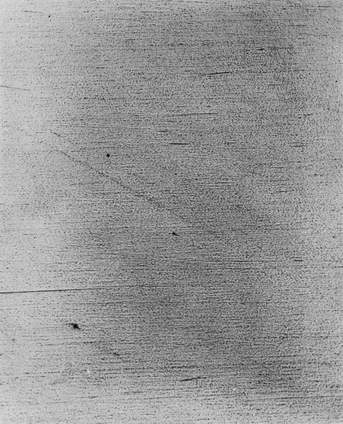
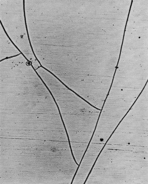
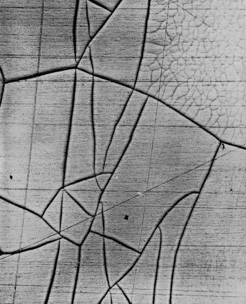
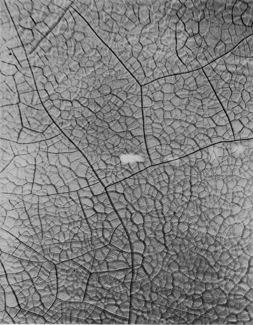
With the increasing importance of the micro-crack pattern in practice, and in the literature, the need has arisen for a means of description. It is recommended, first, that frequency be defined in terms of cracks per lineal inch, since measurement on the basis of ASTM grain sizes has been found inadequate. It is further proposed that cracks be classified as to type, since this does not necessarily follow the frequency of cracking. Based on work by the Ternstedt Detroit laboratories, the following basic patterns are recognized, arranged here in what is presently felt to be their order of desirability, the most desirable first, all illustrations in the originals being at 100× magnification:
Type 2M: Two fine mesh patterns (Fig. 18), each being most distinct at a different focus depth. A number following the letter M would denote the number of cracks traversed in moving a point one lineal inch in a direction normal to the direction of the greater number of cracks. For example, 2M-1600 would indicate a dual M micro-crack pattern with 1600 cracks per lineal inch.
Type M: Same as 2M, except that there is only one instead of two distinct patterns. Type M will change to type 2M with increased chromium thickness. Type M is shown in Fig. 19.
Type W: Incomplete formation of cracks, or "worm tracks" (Fig. 20).
Type P: Porous chromium (Fig. 21). Nickel exposed through pores instead of cracks in the chromium layer.
Type Y: Coarse or forked pattern with fewer than 300 cracks per lineal inch (Fig. 22).
Type O: Only normal random discontinuities in the chromium surface (not illustrated).
Generally there will be areas in which these basic patterns will occur in combinations, and such patterns would be designated by combinations of the appropriate letters. For example (Fig. 23), a pattern combining type Y and M in which the Y cracks predominate would be designated YM. Where the M is predominant in such a combination (Fig. 24), the designation would be MY.
The arrangement of preference shown here is subject to some variation below type M, depending upon the exact nature of the structure. Most important is the area of nickel exposed, and the uniformity of its distribution.
A rough approximation of the thicknesses at which some of these patterns may be expected to occur in a bath combination producing type M at a thickness of thirty to forty millionths under given conditions may be useful as a frame of reference:
Adoption of the dual chromium process for the plating of die castings has led to a great improvement in the quality of product. That this is true is borne out by the continuing resurgence of the use of die castings in Ternstedt's particular lines of products. Whether these applications will continue to be plated die castings will depend greatly on how well the improvement of quality can be continued in the face of keen competition from other materials and processes. This competition is no longer merely one of cost. Quality today is a major demand, and is going to remain so.
As to the technical aspects of this paper, the authors would note that there is still a great deal to be learned about the process, particularly in the area of control. A great deal is still to be learned about racking. Nevertheless, even where recesses now prevent achievement of the optimum pattern over the entire part, there is still a very great benefit to be derived from the process.
Plate thickness, at least in this system, does not guarantee corrosion resistance, and requirements on this score should be considered secondary to accelerated corrosion testing, except as a means of obtaining the desired pattern.
The dual chromium process is capable of very extended basis metal protection when properly applied over sound substrates. A few examples have been cited in this paper, and the Ternstedt Detroit and Columbus plants are consistently obtaining more than 100 hours CASS exposure without failure on steel parts of relatively simple shapes. In this connection, it is of interest that parts ten years old have been recovered from cars in good condition, and upon microscopic examination proved to have a fairly good crack pattern; in this case of course obtained accidentally.
Finally, in this, as in any other system, there is no substitute for good general plating practice and attention to detail, and this can only be obtained through the interest, organization and cooperation of the people actually on the machines. A display including current CASS tested parts, Hull cell panels, and analytical data is maintained at each machine, and has been found most useful in enlisting the support of such people in maintaining the quality of parts in the dual chromium system.
Acknowledgements
The authors are indebted to Mr. R. J. Heusel and Mr. C. F. Nixon for invaluable advice and assistance in the preparation of this paper. The collaboration of Mr. J. D. Thomas with Mr. Hardesty in the conduct and assessment of the "half-box" tests made the inclusion of this data possible in the limited time available. The authors are particularly indebted to Mr. A. Gonas and Mr. G. Dominick, who are responsible for the graphic illustrations which are a major part of this paper, and to Mr. H. Kahler, who made available preliminary results of the General Motors car survey. Most of all, perhaps, the authors are indebted to the many unnamed people in our plants who have developed the process and made it work.
Appendix
Chromium plating procedure for test panels
The protective coating is removed from the buffed pre-plated panels and the surface wiped with a solvent-wet cloth to remove any residual organic material.
After attaching wire lead (usually by soldering), the panel is cleaned cathodically for about one minute using a light-duty general purpose cleaner at six volts and 140°F.
The panel is then rinsed, inspected for water breaks, and the cleaning step repeated if necessary until freedom from water breaks is obtained. Rarely, it may be necessary to scrub lightly with a stiff bristle brush.
The panel is then immersed for 15 to 30 seconds in dilute (¼ to ½%) sulfuric or hydrochloric acid to neutralize any residual alkali.
After rinsing and inspection for water breaks, the panel is activated cathodically for one minute at 6 V in a 2.0 oz./gal solution of sodium cyanide at room temperature, and again rinsed.
The panel is then inserted in the half-box, which has been previously suspended awash in the chromium bath, and electrically connected to the DC power source which has been preset to supply the desired total current. The power source is then switched on and plating proceeds, with such current adjustments as may be necessary, for such time (determined by previous experiment) as may be required to obtain the desired thickness.
After rinsing, the panels are dried and stored in a desiccator until corrosion tested.
References
1. C.F. Nixon, SAE Journal, 68 (9), 60 (1960).
2. H. Kahler, Private communication.
3. W.E. Lovell, E.H. Shotwell & J. Boyd, Tech. Proc. Am. Electroplaters' Soc., 47, 215 (1960).
4. G.L. Sukes, Metal Finishing, 57 (12), 59 (1959).
5. C.F. Nixon, J.D. Thomas & D.W. Hardesty, Tech. Proc. Am. Electroplaters' Soc., 46, 159 (1959).
6. ASTM A-219-45T “Methods of Test for Local Thickness of Electrodeposited Coatings,” ASTM International, West Conshohocken, PA (1945; Replaced 1972).
7. W.H. Safranek, H.R. Miller & C.L. Faust, Tech. Proc. Am. Electroplaters' Soc., 46, 134 (1959).
8. A.H. DuRose, Tech. Proc. Am. Electroplaters' Soc., 47, 83 (1960).
9. J.D. Thomas, D.W. Hardesty & C.F. Nixon, Tech. Proc. Am. Electroplaters' Soc., 47, 90 (1960).
10. W.H. Safranek, H.R. Miller, R.W. Hardy & C.L. Faust, Tech. Proc. Am. Electroplaters' Soc., 47, 96 (1960).
11. W.M. Spurgeon & O. Isaacs, Tech. Proc. Am. Electroplaters' Soc., 45, 145 (1958).
12. R.L. Saur, Plating, 45 (12), 1232 (1958).
Related Content
The New Wild West of Automotive Finishing
The advent of the EV and new application opportunities for finishers.
Read MoreTitrations: To Automate or Not to Automate?
What considerations should you keep in mind for automatic titrations? Conor McAnespie of Hanna Instruments discusses the benefits of auto titrators.
Read MoreTin and Tin Zinc Overview and Growth
Brett Larick of Columbia Chemical discusses the increasing demand for conductive finishes driven by the increasing electrification of vehicles.
Read MoreHenry Ford Is Still Right When It Comes to Color
Who would have imagined that more than 100 years after his famous statement about any color as long as it’s black would still have relevance of a sort?
Read MoreRead Next
A ‘Clean’ Agenda Offers Unique Presentations in Chicago
The 2024 Parts Cleaning Conference, co-located with the International Manufacturing Technology Show, includes presentations by several speakers who are new to the conference and topics that have not been covered in past editions of this event.
Read MoreEducation Bringing Cleaning to Machining
Debuting new speakers and cleaning technology content during this half-day workshop co-located with IMTS 2024.
Read MoreEpisode 45: An Interview with Chandler Mancuso, MacDermid Envio Solutions
Chandler Mancuso, technical director with MacDermid Envio discusses updating your wastewater treatment system and implementing materials recycling solutions to increase efficiencies, control costs and reduce environmental impact.
Read More









.jpg;maxWidth=300;quality=90)


