Increasing Vibratory Efficiency by Optimizing the Choice of Media Shape Relative to Part Geometry
When choosing vibratory media, understand the size, shape, starting roughness condition and metallurgical structure of the part.
Abstract
Vibratory processing is frequently used for generic deburring or in chemically accelerated vibratory finishing processes to minimize or eliminate hand polishing. When properly used, not only can polishing costs be dramatically reduced, but part quality can also be improved, especially prior to decorative nickel/chromium final electroplating. When choosing vibratory media it is imperative to understand the size, shape, starting roughness condition and metallurgical structure of the part. These variables dictate the media composition, size and shape necessary to finish the part effectively in the shortest time possible, while achieving the desired surface finish at the lowest possible cost. This paper generically reviews media size and shape, specifically as that size and shape is related to the geometry of the part to be refined. Insights are shared relevant to media shapes pertinent to accomplishing various finishing tasks. Additionally, a review of the benefits and drawbacks to media shape will be addressed, especially as related to the shape of the parts being finished compared to the three major media characteristics of length, width and density. Finally, a quick review of media attrition as related to composition will be presented as an understanding of a media’s attrition rate is instrumental to understanding the volume of media sludge that will be generated, and therefore the consumable cost of the media choice relative to the cost of the deburring operation.
Introduction to Vibratory Finishing
Vibratory processing is frequently used to eliminate hand polishing. Vibratory finishing’s advantage is that it can reduce the expensive overhead of hand labor via the benefit of mass finishing hundreds if not thousands of parts simultaneously. In hand polishing operations, a polishing belt is the tool of choice for surface refinement (Fig. 1). In vibratory finishing however, preformed vibratory media replaces the polishing belt as the tool for improving part surface quality (Fig. 2).
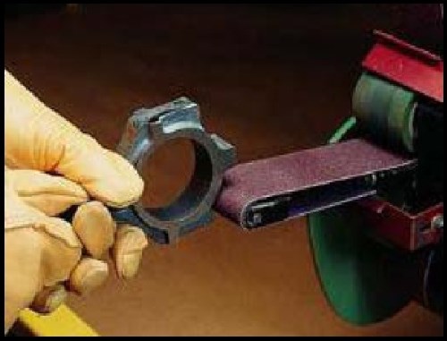
Figure 1 - An automotive connecting rod being hand polished with a polishing belt.
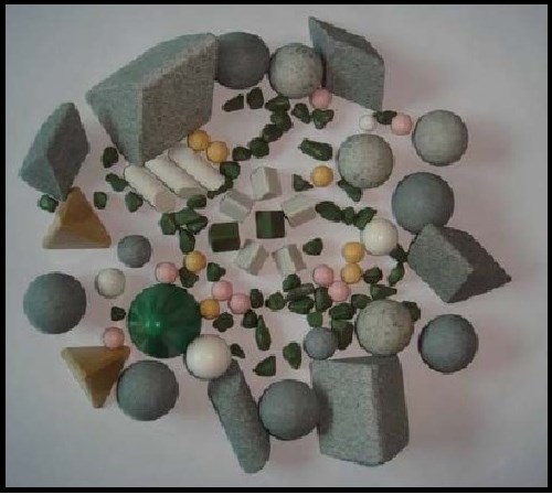
Figure 2 - An assortment of ceramic and plastic media in a variety of sizes and shapes.
Understanding Media Grades
An amateur wood worker who purchases sandpaper at a hardware store will find sandpaper available in a variety of grades. Likewise, the vibratory finishing operator is faced with a variety of choices when choosing a suitable media for the finishing task to be accomplished.
The most commonly employed mass finishing media is abrasive ceramic media.1 This media is composed of a ceramic binder and abrasive grit.1,2,3 By altering the ratio of grit to binder, or by choosing different grit grades, the media manufacturer can alter the aggressiveness of the media.1,2,3
The ceramic binder is itself, a blend of sand, clay and feldspar.2 Also, by changing the ratio of these binder sub-components to one another, the media manufacturer can alter the kiln-firing, vitrification temperature and consequently the media’s attrition rate1,3 (Fig. 3)
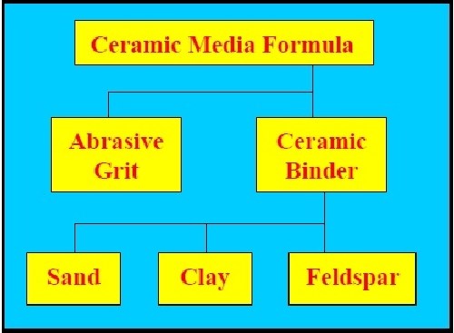
Figure 3 - The make-up of a typical abrasive ceramic media.
In general, the higher the vitrification temperature during kiln-firing, the denser the media and the lower is the media’s attrition rate. In general, high temperature, vitrified media maintains its size and shape longer because of this durability.3
Polishing belts are purchased by choosing first and foremost, the abrasive grade content of the aluminum oxide resin-impregnated on the belt. Likewise, media abrasiveness is usually specified by different grades, more commonly referred to as bonds3,4 (Table 1).
Table 1 - Common media bonds, binder/abrasive ratios and approximate media density values.3
Media Bond Number | Percent Porcelain Binder | Percent Al2O3 Abrasive | Media DensityA (lb./ft3) |
High density | 0 | 100B | 125 |
0 | 100C | 0 | 90 |
10 | 92 | 8 | 88 |
20 | 85 | 15 | 85 |
30 | 75 | 25 | 82 |
40 | 65 | 35 | 80 |
50 | 55 | 45 | 78 |
60 | 40 | 60 | 75 |
70 | 25 | 75 | 72 |
Al2O3D | 0 | 100 | 70 |
A = Based on the author’s experience. B = Vitrified, 100% aluminum oxide media. C = Pure porcelain binder, no Al2O3 abrasive. D = 100% mineral Al2O3, non-kiln fired/non-vitrified. | |||
By examining Table 13, it can be seen that as the ratio of abrasive content increases in the media bond, the ceramic binder content must also decrease.1,3 Since the abrasive is less dense than the ceramic portion of the media, the higher the abrasive concentration, the lower will be the media density.
Since the ceramic binder is the glue that holds the media together, as its content decreases with an increase in the abrasive content, the higher the media’s deterioration rate will become.3 Simply stated, there is less glue present to hold the piece of media together.
The rate at which media deteriorates is known as its attrition rate. Unfortunately, when vibratory finishing department personnel are considering the selection of a new media, never does the manufacturer’s literature detail the attrition rate of the media in anything other than euphemistic phrases such as “fast cutting,” “moderately abrasive” or “long lasting.” The sales brochure will seldom state the media’s actual attrition rate. Therefore, it becomes a guessing game of trying to interpret the verbal descriptions versus the task at hand.
As a result of this sales literature citation deficiency, Table 2 has been compiled.3 Based on the author’s experience, attrition rates have been assigned to the previously cited media bonds in Table 1.
Table 2 - Attrition, swarf and processing time.3
Media Bond Number | Attrition rateA (%/hr) | SwarfB (lb./hr) | Swarf in a 20-ft3 vib. bowlC (lb./hr) |
Hi δD | 0.008 | 0.080 | 0.133 |
0 | 0.100 | 1.000 | 1.152 |
10 | 0.130 | 1.300 | 1.464 |
20 | 0.350 | 3.500 | 3.808 |
30 | 0.750 | 7.500 | 7.872 |
40 | 1.200 | 12.00 | 12.29 |
50 | 2.000 | 20.00 | 19.97 |
60 | 2.750 | 27.50 | 26.40 |
70 | 3.500 | 35.00 | 32.26 |
XA | 4.000 | 40.00 | 35.84 |
A = Based on the author’s experience and measurements. B = Assumes 1,000 lb. of media in vibratory bowl at T = zero. C = 20-ft3 vib. bowl with 16 ft3 usable volume and 12.8 ft3 of media. D = High-density, vitrified aluminum oxide media. | |||
A Simple Technique for Calculating Media Sludge Generation
Let us assume for illustrative purposes that the vibratory finishing department has a 20 ft3 vibratory bowl with 16 ft3 of usable capacity. Additionally, let us assume that the operator loads the machine at an 80% media-to-20% parts ratio. It is now possible to calculate the volumetric displacement of the media and parts:
Media = (16 ft3)(0.8 usage) = 12.8 ft3 media
Parts = (16 ft3)(0.2 usage) = 3.2 ft3 parts
Now let us make the following additional assumptions for this example:
1. Media is a 40-bond.
2. The processing time is 2.0 hr.
Using the data found in Tables 1 and 2, it is possible to determine the actual weight of media consumed and therefore the weight of media sludge generated for the two-hour processing cycle as follows:
1. From Table 1, 40-bond media has a weight density of 80 lb./ft3.
2. From Table 2, 40-bond media has an attrition rate of 1.2%/hr.
A two hour processing cycle will generate the following weight of media sludge:
(12.8 ft3)(80 lb./ft3)(2.0 hr)(0.012/hr) = 24.6 lb. of media sludge
Media vs. Part Contact Patterns
To maximize the rate of part refinement in the vibratory bowl, one must additionally maximize the media-to-part contact efficiency. When considering the efficiency of contact between these opposing surfaces, there are three types of contact patterns possible: planar, linear or point contact.
Planar contact
Planar contact occurs when the flat portion of the part being vibratory-finished is contacted by the flat face of a piece of media (Fig. 4). This type of contact pattern offers maximum surface-to-surface abrasive contact and consequentially usually the shortest processing time (Fig. 5).

Figure 4 - A good example of planar contact.
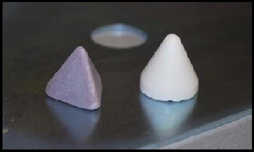
Figure 5 - Additional examples of planar contact patterns. Note that although the cone on the right has curved sides, it demonstrates planar contact when its flat base contacts the flat work piece.
Linear Contact
Linear contact is the result of curved surface-to-flat surface contact. The resulting contact pattern is a line also known as a tangent line. There are three combinations of media and parts that result in linear contact:
1. A flat part contacted by a curved piece of media (Fig. 6),
2. A curved work piece contacted by a flat media face (Fig. 7) or
3. A curved part contacted by curved media (Fig. 8).
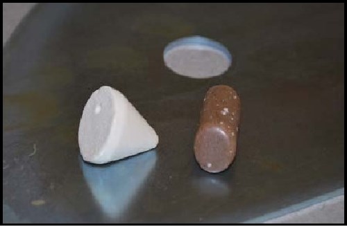
Figure 6 - Linear contact pattern No. 1: flat work piece and linear, tangential, media contact.
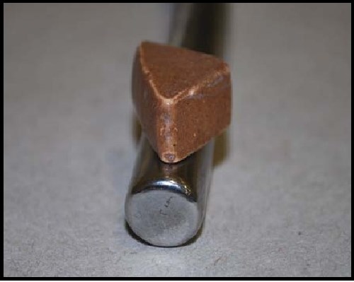
Figure 7 - Linear contact pattern No. 2: curved part contacted by a flat media face.

Figure 8 - Linear contact pattern No. 3: curved part contacted by curved media.
Linear contact is not as efficient as planar contact, because a smaller percentage of the part’s total surface area is being contacted per unit time.
Point Contact
Point contact occurs when either spherical media contacts a flat part or when flat media contacts a spherical part. If the part to be vibratory finished is flat then planar contact can be attained by using flat media. Spherical media is typically utilized for peen polishing operations and as such is not typically a media choice that is used during normal abrasive ceramic vibe operations (Fig. 9).
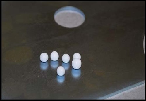
Figure 9 - A point contact pattern which occurs when a sphere contacts a flat face. In this example, the work piece is flat and the vibe processing media is spherical.
Advantages and Disadvantages of the Assorted Contact Patterns
As noted earlier, the most efficient contact pattern, planar contact, occurs when a flat part is contacted by the flat-face of a piece of media. This pattern is most efficient because it maximizes the percentage of part area under refinement at any one time. The slight disadvantage of planar contact is that the inertial impact force of media contact is diffused across the entire area of the contact pattern. Therefore contact force in any singular location is not as concentrated.
During linear contact, the total surface area on the part being contacted at any one time is reduced to a uni-dimensional line. A slight advantage to linear contact is that the entire density of the media piece is concentrated along that line. However this advantage is lost during processing in that the part must be processed longer to insure that all areas of the part are eventually contacted. Additionally, the advantage, if captured, cannot be maintained because media attrition results in loss of mass that more often than not, is not exactly counteracted with the addition of new media to the vibratory bowl.
Similarly, point contact follows the same logic as the linear pattern. In point contact the area of contact efficiency is at its minimum because the point of contact is a singularity. However, 100% of the weight of the media is concentrated onto that contact point. In other words, a lot of work is done at once, but on an infinitesimally small contact area. Vibratory run time may be protracted since all part areas must eventually be contacted.
Part and Media Shape as Related to Contact Efficiency
Concomitant to the discussions of the types of contact patterns possible, by in large, efficiency is driven by planar contact. Unfortunately, parts destined for vibratory finishing come in assorted sizes and shapes. Additionally the parts may be complicated with blind holes, through-holes, I.D. corners, sharp angles, grooves, narrow slots and a wide assortment of geometries that complicate the choice of media. As a result other considerations must be made when choosing a media size and shape.
Media Lodging
First and foremost in choosing a vibratory media for a complex geometry part or a part with I.D. surfaces is to choose media that will not lodge in that part (Fig. 10).
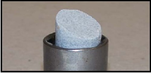
Figure 10 - A cylindrical work piece containing lodged, cylindrically-shaped media.
Media lodging is and always will be the bane of parts that have I.D. surfaces. A bowlful of parts, within which media has lodged will obviate the efficiency of mass finishing operation with hand labor to remove the lodged media. Despite judicious forethought in a choice of media size and shape, a high attrition rate media will decrease dimensionally at a marked rate. Therefore what may not be a lodging problem during the first week of use may very well become a lodging problem during week two. To minimize lodging one should choose media having the lowest practical attrition rate that is conducive to an acceptable processing time and also forestalls the onset of lodging as the result of attrition (Fig. 11).
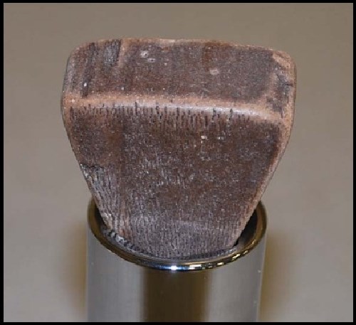
Figure 11 - The same cylindrical part as shown in Fig. 10, except the media size and shape has been changed. Note how the wider base of this isosceles triangle-shaped media prevents it from lodging in the I.D. of the cylinder.
Additionally, some logical forethought should be given to the shape of the media. The same part is shown in Figs. 10 and 11. Cylindrical media is a poor choice for a part that has a cylindrical I.D. shape, as eventually, the media will diminish in size, and lodge perfectly. The lodging can be eliminated by choosing a shape what will not lodge regardless of reduction in size.
Part Geometry vs. Media Selection
An additional critical concern when choosing a media for a complex shaped workpiece is to maximize contact efficiency. This means, as much as possible, choosing a media size and shape that complements the opposing surfaces relevant to achieving planar contact. This in general is usually the best option for fastest refinement times.
A poor choice of media may therefore result in minimal, if any, contact in a recessed location such as a sharp I.D. angle. This may be an important concern especially if the area that can’t be contacted is the critical area slated for surface improvement (Figs. 12 and 13).
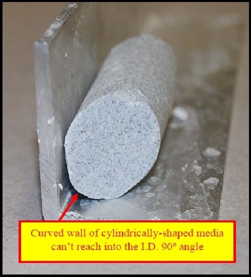
Figure 12 - A cylindrical piece of media that is being used to deburr an I.D. 90º angle. The curved side of the cylinder prevents its contact in the I.D. corner.

Figure 13 - A poor media choice for gear tooth refinement. Note that the cylindrical media is not the correct size and shape to reach the lower flanks of gear teeth. A gap is visible on the tooth flanks beneath the media’s curved shape.
Better media choices for these two part geometries are shown in Figs. 14 and 15.
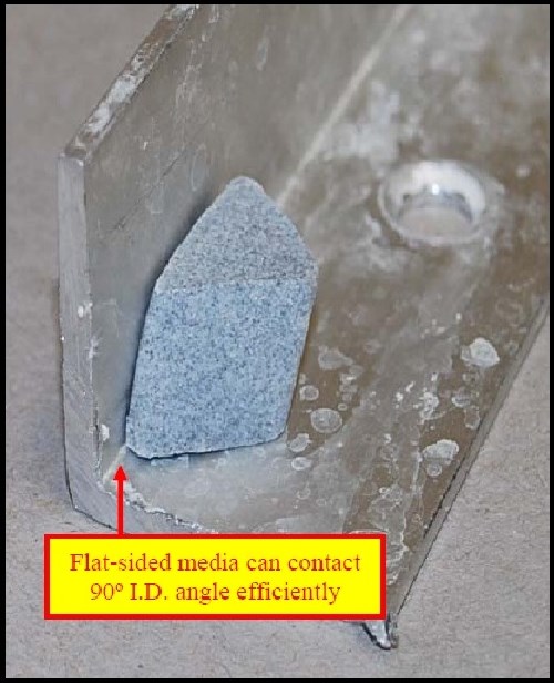
Figure 14 - An angle cut triangle, the flat faces of which ensure more efficient contact in the 90º I.D. corner.

Figure 15 - An ellipse-shaped media is a better choice than a cylinder for more efficient contact on the gear tooth flanks.
Media Geometry vs. Media Selection
As discussed earlier, it is always best to maximize contact of media face-to-part face. To this end, an examination of assorted media shapes relevant to their geometry can give an indication of the potential efficiency of contact (Fig. 16).
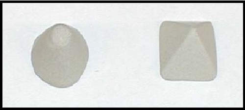
Figure 16 - Two common media shapes: (L) a 1” cone and (R) a 1” tetrapyramid.
Figure 16 shows two styles of media - a cone and a tetrapyramid. If we are choosing media for the maximum percentage of available flat contact possible, then the tetrapyramid would be the choice. The tetrapyramid has five, flat sides, consisting of a 1” square flat base and four, 1” equilateral triangle sides. Regardless of the orientation direction of the tetrapyramid media to the part, contact will be made and then maintained as planar contact (Fig. 17).
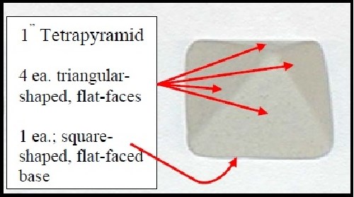
Figure 17 - The five contact faces of a tetrapyramid shape.
The cone-shaped piece of media shown in Fig. 16 has only one flat-face for maximum part contact. The balance of the cone - its sides, can generate only linear contact.
Determining the Efficiency of Flat Face Contact by Media Type
Flat face surface area calculation
It is possible to determine the surface area of flat-face contact that a piece of media possesses. The following is a hypothetical example for a better understanding.
Using the media in Fig. 16, we know the cone has a 1” diameter base and is 1” tall and the tetrapyramid has a 1” square base and four equilateral triangle sides with a 1” base and height.
The cone’s flat-face area contribution to part contact is only possible when the base contacts the work piece. Using the formula for the area of a cone,
A = πr2 + πrl,
the area of the cone is determined to be 2.36 in2. However, the percentage of this area which is flat is only 0.79 in2 or 33.47% of the total surface area of the cone.
Using the formula
(b2) + (4)(½bh),
the area of the tetrapyramid is determined to be 3.0 in2. Since all of the tetrapyramid’s five faces are flat, 100% of that surface area represents flat-face contact surface area.
Determining total flat-face surface area contact per cubic foot of media volume
We can now expand the above example to determine the total contact area per cubic foot of each media shape. The formula for the volume of a cone is
V = dh/3,
where d = the diameter of the cone base and h = the cone height. Using this formula, the volume of a cone media piece is 0.33 in3. Since 1 ft3 = 1,728 in3, one cubic foot contains 5,236 pieces of cone media. Since each piece of cone media has only 0.79 in2 of possible flat-face contact area, one cubic foot of cone media has a total flat-face contact area of 4,136 in2, or 28.73 ft2.
The formula for the volume of a tetrapyramid is
V = Ah/3,
where A = base area and h = height. Using this formula, a 1” tetrapyramid occupies 0.33 in3, the same volume as the cone. However, the tetrapyramid is 100% flat-face contact area. Its 5,236 pieces/ft3 of volume represents 15,708 in2 or 109 ft2 of possible flat-face surface contact area. There is 3.79 times the available flat-face contact surface area when using a tetrapyramid as opposed to a cone.
The Reduction of Contact Efficiency Caused by Media Attrition
All media, regardless of bond, has an attrition rate. Therefore, during vibratory operations, media is continuously wearing down. The attrition rate based on the media composition was detailed earlier in Tables 1 and 2. Unfortunately, it is difficult for an operator to note volumetric decrease in the media mass.
An analogy to this observation would be noting the rate at which hair on your head grows. We know it grows, because with periodic regularity a haircut is required. However, on a day-to-day basis, the increase in hair length is imperceptible.
The same is true for media attrition. On a day-to-day basis for most media, all except perhaps for the highest of attrition rate materials, it will be nearly imperceptible to note loss of the media mass. Yet when examined on a weekly base, the level of media mass in a vibratory bowl will be measurably reduced.
Consequential to this loss in volumetric mass in the vibratory bowl are a number of factors which may negatively influence the final quality of the parts and the overall required processing time.
Part-on-Part Contact Damage Resulting from Media Loss Caused by Attrition
In order to generate an appropriate pre-electroplate quality on hardened steel parts, the standard loading ratio of media to parts is 80 to 20% respectively. Assume that a vibratory bowl is filled with 12.8 ft3 or 1,088 lb. of 40-bond media and 3.2 ft3 of parts. By consulting Tables 1 and 2, we can determine that the attrition rate for 40-bond media is 1.2%/hr and its density is 80 lb./ft3. Let us also assume that the bowl is run for 16 hr/day for 12 production days. If no new media is added to the bowl for these 12 production days, the following will hold true:
Calculation #1:
(16 hr/day)(12 days)(0.012 lb./hr)(80 lb./ft3) = 184.32 lb. media will be consumed.
Calculation #2:
(1,088 lb. – 184.32 lb.) / 80 lb./ft3 = 11.30 ft3 media remains in the vibratory bowl.
Calculation #3:
3.2 ft3 parts + 11.30 ft3 media = 14.50 ft3 mass.
Calculation #4:
(3.2 ft3 parts ÷ 14.50 ft3)(100) = 22.07% parts.
By not adding media to the bowl for two weeks, the ratio of parts-to-media will change. In this example, the ratio of parts to media has increased by 10%, although the number of parts has remained the same. As a ratio of parts increases vs. the available media mass present to keep the parts separated from one another, so do does the propensity to generate part-on-part contact damage (Fig. 18).
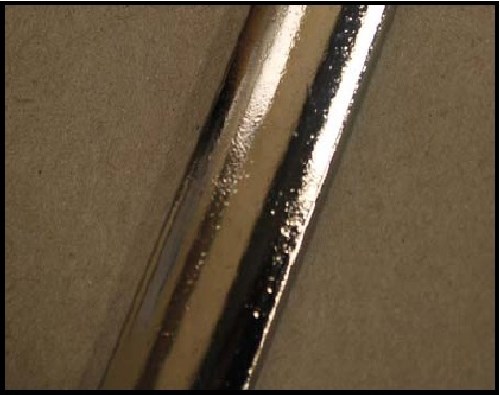
Figure 18 - A plated part showing part-on-part damage - the result of low media level in a vibe bowl.
Increased processing time relevant to reduced media mass
As the overall volume of media mass decreases, so too does the volume of each piece of media (Fig. 19). As media decreases in size, so too does its ability to transfer energy to abrasively deburr the parts. The smaller the media volume, the smaller its inertial impact on the parts and the less work it will accomplish as it contacts the parts (Fig. 20).
Figure 19 - The relative media size decrease after several months of vibratory bowl run time. Note the decreasing size and volume of the media caused by attrition.
Figure 20 - A ½” media cube superimposed into an invisible outline of its original 1” cube volume. Note that its final size at ½” per side is half its original 1” per side dimension. However, its volume has decreased exponentially by the cubed root of its original volume. It now occupies just one-eighth its original volume.
Consider the volumetric decrease in media size relative to the cube shape shown in Fig. 20. When a cube with original dimensions of 1” per side is reduced to ½” per side, the cube does indeed measure ½” per side, exactly one-half of its original linear dimensions. However, it has decreased in volume by ⅞ of its original volume. The overall volume of the cube has actually decreased exponentially by its cubed root.
Conclusions
• Media comes in different bonds within which the ratio of the ceramic binder-to-abrasive content varies.
• The higher the ratio of ceramic binder-to-abrasive the greater the density of the media bond.
• The higher the abrasive content in a media bond the greater its attrition rate.
• The higher the attrition rate of a media bond the greater its sludge generation.
• Media is available in dozens of sizes and shapes.
• The choice of media size and shape to use is related to the geometry of the part being finished and the propensity of the final media size and shape chosen not to become a lodging problem.
• The efficiency of media-to-part contact is related to the final shape of media chosen to complete the task.
• The total area of media flat-face contact per cubic foot of media can be used to predict processing efficiency.
• As media mass is reduced by wear, its ratio to the parts mass decreases, increasing the propensity to cause part-on-part damage.
• As media mass decreases so too does the available area present to do work on the parts in the vibratory bowl.
References
1. G. Ward, personal communication, Vibra-Finish Media South, Marion, KY (2008).
2. E. Holzknecht, personal communication, Rösler Metal Finishing USA, LLC, Battle Creek, MI (2007).
3. W.P. Nebiolo, “An Investigation of Vibratory Media in Relationship to the Performance of Vibratory Finishing,” in Proc. SUR/FIN 2008, NASF, Washington, DC, 2008; p 53.
4. W.P. Nebiolo, “The Basics of Surface Engineering by Isotropic Superfinishing Using a Traditional Vibratory Finishing Bowl,” in Proc. SUR/FIN 2006, NASF, Washington, DC, 2006; pp. 43-52.
5. W.P. Nebiolo, “An Easily Understood Technique for Measuring Vibratory Bowl Speed and Optimizing Vibratory Bowl Processing Efficiency,” in Proc. SUR/FIN 2007, NASF, Washington, DC, 2007; pp. 42-49; also Plating & Surface Finishing, 95 (4), 14-18 (2008).
Related Content
SUR/FIN 2023 Registration Is Now Open
The National Association for Surface Finishing SUR/FIN 2023 surface finishing industry trade show will take place June 6-8, 2023 in Cleveland, Ohio.
Read MoreElectroplating in the Context of Worldwide Nanotechnology Initiatives: A Heritage Paper
In the first part, a summary is presented on recently established nanotechnology initiatives in various countries around the world. Program funding levels and core activities will be compared to provide a basis for assessing business opportunities for various industries. The second part of the paper looks at specific examples of nanostructures made by electrochemical methods currently at various stages in their development, or already in use.
Read MorePlating, Anodizing Equipment for Variety of Applications
Titan Metal Fabricators Titan Metal Fabricators, Rightech Fabrications and Optimum Anode Technologies are leading suppliers of equipment for the plating and anodizing industries.
Read MoreRead Next
Delivering Increased Benefits to Greenhouse Films
Baystar's Borstar technology is helping customers deliver better, more reliable production methods to greenhouse agriculture.
Read MoreA ‘Clean’ Agenda Offers Unique Presentations in Chicago
The 2024 Parts Cleaning Conference, co-located with the International Manufacturing Technology Show, includes presentations by several speakers who are new to the conference and topics that have not been covered in past editions of this event.
Read MoreEducation Bringing Cleaning to Machining
Debuting new speakers and cleaning technology content during this half-day workshop co-located with IMTS 2024.
Read More











.jpg;maxWidth=300;quality=90)


