NASF/AESF Foundation Research Project #123: Electrochemical Manufacturing for Energy Applications – 3rd Quarterly Report - Part I
This is the third quarterly report, covering work during July-September 2022 and consists of a review, “Formidable Challenges in Additive Manufacturing of Solid Oxide Electrolyzers (SOECs) and Solid Oxide Fuel Cells (SOFCs) for Electrolytic Hydrogen Economy toward Global Decarbonization,” prepared and submitted to the peer-reviewed Ceramics Journal for publication. What follows here is Part I of the review paper, covering the literature on additive manufacturing of SOFCs and SOECs. Part II, covering opportunities and challenges for additive manufacturing technologies, will be published in January 2023.
by
Majid Minary Jolandan*
A Note from the AESF Foundation Research Board
The NASF-AESF Foundation Research Board has selected a project on electrodeposition toward developing low-cost and scalable manufacturing processes for hydrogen fuel cells and electrolysis cells for clean transportation and distributed power applications. This report is the 3rd quarterly report, covering work during July-September 2022. Since the beginning of this project in January 2022, the Project Director, Dr. Majid Minary Jolandan, has been affiliated with Arizona State University (ASU), as Associate Professor of Mechanical and Aerospace Engineering in the School for Engineering of Matter, Transport and Energy of the Ira A. Fulton School of Engineering.
During this July-September quarter, Dr. Minary has decided to move to the University of Texas at Dallas (UTD). Accordingly, this report covers a condensed period from July 1 to August 8, 2022.
As is standard practice with academic contracts, the grant will follow the awarded professor (Dr. Minary). Logistically, there has been an offset in the program with no work was performed from August 8 to October 1, 2022. On Oct 1, UTD initiated the grant, and the work will continue and proceed for the next three years and one quarter, pending subsequent board approval for each additional year.
Accomplishments during the quarter
During the transition period, a review was prepared and submitted to the peer-reviewed Ceramics Journal for publication. What follows here is Part I of the review paper. Part II will be published in January 2023. A printable PDF version of Part I is available by clicking HERE.

Formidable Challenges in Additive Manufacturing of Solid Oxide Electrolyzers (SOECs) and Solid Oxide Fuel Cells (SOFCs) for Electrolytic Hydrogen Economy toward Global Decarbonization – Part I
by
Majid Minary Jolandan
Department of Mechanical Engineering
The University of Texas at Dallas
Richardson, Texas, USA
ABSTRACT
Solid oxide electrolysis cells (SOECs) and solid oxide fuel cells (SOFCs) are the leading high temperature devices to realize the global "Hydrogen Economy". These devices are inherently multi-material (ceramic and cermets). They have multi-scale multi-layer configuration (a few microns to hundreds of microns) and different morphology (porosity and densification) requirements for each layer. Adjacent layers should exhibit chemical and thermal compatibility and high temperature mechanical stability. Added to that is the need to stack many cells to produce reasonable power. The most critical barriers to global widespread adoption of these devices have been their high cost and issues with their reliability and durability. Given their complex structure and stringent requirements, additive manufacturing (AM) has been proposed as a possible technological path to enable low-cost production of durable devices to achieve economies of scale. However, currently, there is no single AM technology capable of 3D printing these devices at the complete cell level, or even more difficult at the stack level. This article provides an overview of challenges that must be overcome for AM to be a viable path for manufacturing of SOECs and SOFCs. A list of recommendations is provided to facilitate such efforts.
Keywords: SOEC, SOFC, hydrogen economy, renewable energy, decarbonization, additive manufacturing, market competitiveness, scale-up and high-volume manufacturing.
1. Introduction
Hydrogen, as an important chemical feedstock in the global economy, has growing demands in transportation, steel production, power generation and load balancing in grid services. Recently, there has been a significant global investment in the “Hydrogen Economy”, which in turn will advance manufacturing and recycling of clean hydrogen technologies. For example, in the United States, the mission of the Department of Energy’s “Hydrogen Shot” is to reach $1 per 1 kg in 1 decade (“1 1 1”) for hydrogen. Sectors such as long-distance transport via heavy- and medium-duty vehicles, high-temperature heat, energy storage and synthetic fuels for air and marine transport are among the energy intensive and difficult sectors to decarbonize. Hydrogen has been proposed as a key energy option for decarbonization of these sectors (Figure 1).
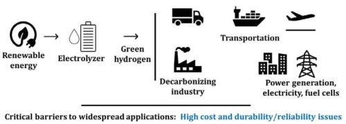
Figure 1 - The role of fuel cells and electrolyzers in the hydrogen economy.
Hydrogen is the simplest element on earth; however, it does not typically exist by itself in nature. It must be produced through chemical reactions from compounds that contain it. Currently, the majority (~95%) of the world’s hydrogen is produced by steam methane reforming (SMR) that releases greenhouse gas CO2. The electrolytic hydrogen (without any pollution) is more expensive compared to hydrogen produced using SMR process.1 Today’s hydrogen market is approximately 10 million metric tons per year (MMT/yr) in the U.S. and 65-100 MMT/yr, globally. However, only approximately 2% of total global hydrogen production is generated via electrolysis. The electrolytic hydrogen market could grow substantially to at least 100 MMT/yr by 2050 to meet potential future demands and help difficult to decarbonize sectors. To meet this market size, the U.S. electrolyzer capacity will likely have to increase from 0.17 gigawatts (GW) today to up to 1,000 GW in 2050 - or 20% compound annual growth from 2021 to 2050 with an annual manufacturing requirement of over 100 GW/yr.2 In addition, over 50 GW of domestic fuel cell capacity is required in the decarbonization scenario with an annual manufacturing requirement of over 3 GW/yr. Investments in manufacturing and process development and increasing production scale and industrialization will reduce the cost of electrolytic hydrogen.
SOFCs and SOECs are considered among the electrochemical energy storage and conversion devices that are essential for global rollout of hydrogen economy. SOECs are energy storage units that produce storable hydrogen from electricity and water (electrolysis of water), electrolyze CO2 to produce CO and oxygen or even co-electrolyze water and CO2 to produce syngas (CO + H2) and oxygen.3 High temperature steam electrolyzers use both electricity (preferably renewable) and heat (preferably waste heat or a low-cost thermal energy generator such as a nuclear reactor) because they operate with steam. SOFCs convert the chemical energy stored in a fuel (H2, CO, CH4, etc.) to electricity directly through electrochemical reaction (by oxidizing a fuel). SOFCs are often composed of approximately 40–60 individual cells that produce nearly 25 W per cell, interconnected into a single module.4
The key barriers of the existing technologies are fabrication time and cost, quality assurance and quality control, as well as stack durability. Despite their high efficiency, global market rollout of these devices is currently short of economies of scale. The benefits of hydrogen economy will be best played out when it is deployed at scale and across multiple applications. However, perhaps the high cost of these devices, compared to alternative energy systems, is the single most important factor hindering their wide-spread applications.
SOFCs and SOECs and their stacks are geometrically complex, inherently multi-material and multilayer devices. The cells are made of thin active elements (~10-50 μm electrolyte and ~50-300 μm anode and cathode), with different composition and microstructure (porous anode and cathode and dense electrolyte). More than a hundred steps could be involved in the traditional manufacturing process of a complete stack, including tape-casting, screen printing, slip-casting, slurry spraying, spray pyrolysis, dip-coating, thin film deposition, chemical infiltration and ex-solution for catalysts, and laser cutting of the fabricated tapes, punching, laminating, stacking, and firing/sintering.5-7 The large number of steps, with mostly requiring manual inputs and multiple joints and seals, results in low reliability, durability and reproducibility, high cost and long time to market (Figure 2). For global scale adaptation of these devices, manufacturing technologies are needed that reduce the number of cell components in a stack, lower processing temperature, reduce the number of processing steps and shorten the overall processing time. These improvements may result in an increase in throughput and lower-cost production at scale.2
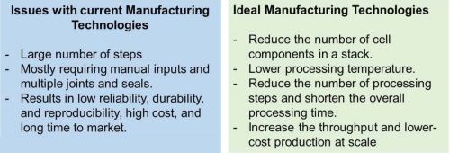
Figure 2 - Issues with current manufacturing technologies for production SOFCs and SOECs and attributes of ideal manufacturing technologies for these devices.
Development or application of suitable additive manufacturing (AM) technologies has the potential to lower the manufacturing cost, decrease waste of often expensive raw materials, provide use of more environmentally friendly materials and processing methods and use of less solvents. AM technologies may reduce the number of steps and result in more durable and reliable devices. Another advantage of AM technologies may be augmentation of the design space for more efficient devices, such as enabling complex geometries beyond planar and tubular ones or enhancing surface area for electrochemical reaction sites and enhanced specific power.8 Thermomechanical modeling of 3D manufactured electrodes for SOFCs and rational design of 3D manufactured composite electrodes point to benefits of 3D printing for performance improvement if certain design criteria are considered.9,10
Given the largely nascent nature of the SOEC and SOFC industries, there is limited data on supply chains needs and constraints.1 High-volume production of these energy devices requires building multi-industry supply chains to support components, materials and equipment.2 Some cell materials and components such as interconnects may face supply chain issues, considering that interconnects are more prone to degradation (cracking, delamination and coating pinholes). AM allows for distributed manufacturing that can elevate some of the concerns in the supply chain.
The goal of this article is to provide a brief overview of challenges that should be overcome for AM to be a viable path for production of these energy devices. The aim is to help identify current bottlenecks and the required R&D strategies that will result in maturation of these technologies and at-scale production of these devices. A list of recommendations is provided to facilitate such efforts. This article does not discuss various AM processes and their working principles in depth. Readers are encouraged to refer to more focused reviews on various processes.5,11-16
2. SOECs and SOFCs Components and Requirements
At the basic level, these electrochemical devices are made of an electrolyte and two electrodes (anode and cathode). Interconnects and sealing materials are also required for complete cells and stacks. The electrolyte and the electrodes should have proper thickness to reduce electric and diffusion resistance. The microstructure and to some extent the thickness of the functional materials in these devices primarily govern the device performance.17 The electrolyte is a pure ceramic, while anode and cathode are ceramic-metal composites (cermet). A dense, thin electrolyte is required to separate oxidation gases from fuel gases. When the cell is electrode-supported, the thickness of the electrolyte can be substantially reduced (to a few microns), which results in significant reduction in the overall ohmic resistance of the cell. Thinner electrolyte, however, limits the number of 3D printing technologies that are applicable. Cathode and anode are a mixture of electrolyte and electrode materials, which is preferred for reduced polarization, and expansion of the triple phase boundaries (TPBs).
ZrO2 doped by Yttrium (Y) or Scandia (Sc) are conductors of oxygen ions above 800°C. Currently, yttria-stabilized zirconia (YSZ) is the state-of-the electrolyte material for SOFCs and SOECs. YSZ can be generally sintered in the range of 1300-1500°C.18 Sc-stabilized zirconia (ScSZ) and gadolinium doped ceria (GDC) have been also used as electrolyte.19 The electrolyte must be sufficiently dense to avoid leakage of the fuel/oxidant gases to the electrodes and reduce the resistance to oxygen ion diffusion in the electrolyte. The electronic conductivity of the electrolyte should be low to prevent losses due to leakage current. The density of the electrolyte, which is related to the porosity, plays an important role in its electrical conductivity. Flaws, pinholes and other defects in the electrolyte can drastically reduce the electrochemical performance of the cell. The sintering step of the electrolyte ceramic is, therefore, vital.
Nickel-YSZ (Ni-YSZ) cermet is used as the anode in SOFC and the cathode in SOEC (considered fuel electrode in both devices). YSZ ceramic in this cermet provides ionic conductivity and structural support, while Ni functions as the catalyst and electronic conductor.20 Cathode in SOFC and anode in SOEC (or the oxygen electrode) can be made of mixed conductors such as lanthanum-strontium cobalt ferrite (LSCF) or lanthanum-strontium cobaltite (LSC). LSCF is a mixed ion-electronic conductor capable of fast oxygen ion and electron conduction. It promotes oxygen reduction reaction as a highly active catalyst. Abundant strontium (Sr)-doped LaMnO3 (LSM) in a cermet with YSZ may be used for less demanding applications. LSM has a good compatibility and low chemical reactivity with YSZ and a similar coefficient of thermal expansion (CTE) to YSZ. In this case, LSM provides electronic conduction and catalytic function, while YSZ is the structural components and provides ionic conduction. In some designs, a buffer layer of gadolinium doped ceria (GDC) is used between the electrolyte and the LSCF cathode. To prevent reaction between the oxygen electrode materials and YSZ, a thin (0.1- to 5-μm) layer of GDC may be also utilized.3
In terms of recycling and circular economy in SOFCs and SOECs, Ni and Lanthanum elements are considered among the materials with environmental burdens. These burdens can be remediated (estimated ~70%) with recycling and considerations of circular economy approach.21
Cathode and anode are porous, electrically conductive and should possess high catalytic activities for fuel oxidation and oxygen reduction, which requires high density of electrochemical reactive sites or triple phase boundaries, TPBs. Electrochemical reaction occurs at the TPBs where electrons, ions and reactants meet. The porosity is required to provide pathways for mass transport, i.e., diffusion of gaseous fuels and byproducts. The polarization in each electrode includes ohmic, activation and concentration polarizations, which should be optimized for overall minimization of the cell polarization.22 Ohmic, activation and concentration polarizations are related to electrical conductivity, triple phase boundary and porosity, respectively. The volume percentage (vol%) of pores is an important factor. Additionally, factors such as proper connectivity (open/close) pores, pore size and size distribution and pore tortuosity, play dominant role in impacting the polarization characteristics.
The porosity is often provided by pore-formers (such as graphitic carbon, short carbon fibers, polymer spheres, flour, rice and starch, etc.), in addition to the pore generated by NiO to Ni reduction.22 In general, larger pore-formers (~20 μm) are more effective than small ones (a few microns).22 A certain vol% of pore-formers is necessary to generate a network of open percolated pores, which is often ~30 vol%. It has been also suggested that composite pore-formers containing two or more pore-formers with different size range can be used to augment the pore network connectivity and tailor the shrinkage kinetics.22 Other methods such as freeze-casting can be also used to generate pores. In freeze-casting pores are generated as a result of ice sublimation in aqueous slurries.23
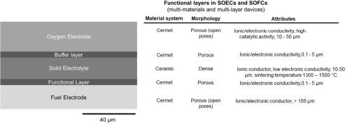
Figure 3 - Side-view schematic of the multilayer structure in a SOEC/SOFC (left). The corresponding materials, morphology and other attributes of each layer (right).
The interconnect is a layer that sits between each individual cell and connects them in series. Interconnects are exposed to both oxidizing and reducing sides of the cell at high temperature, and therefore, have the most demanding material requirements among other cell components in terms of stability. Generally, in these devices two types of interconnects are used, metallic and ceramic oxides.24 Ceramics are more stable (particularly for long-term stability) under oxidizing environments; however, they have lower electrical conductivity compared to metals and are expensive. Metallic interconnects have lower cost, higher electrical conductivity; however, they have less stability than ceramics at high temperature. One approach to increase the stability of metallic interconnects is coating them with protective ceramic layers including oxides, perovskites and spinel. The most common ceramics for interconnect applications include lanthanum and yttrium chromites (YCrO3 and LaCrO3) and perovskite p-type semiconductors.24 AM processes on these particular ceramics are very limited. The main challenge with these materials has been difficulty in sintering Cr-containing oxides due to vaporization of Cr-O species that complicates the sintering process.
Ferritic stainless steels (FSSs) are good candidates among metals, given their low cost, favorable CTE, ease of manufacturing and formation of high electrical conductivity oxides on their surface. Chromium (Cr) evaporation under high operation temperature, however, has been a major limiting factor. Formation of native chromium oxide, which increases the ohmic resistance and chromium poisoning of the SOFC cathode, are two major degradation mechanisms in these devices.24 Metal-ceramic composites (cermets) are also under consideration for interconnects, given their thermal stability at high temperatures and good electrical conductivity.
Sealant is another important component in these devices, for which no AM process has been yet reported. Often, the maximum working temperature of these devices is determined by the glass transition temperature of the sealant. Gas-tight (hermetic) sealants provide electrical insulation (prevent short circuiting) and prevent mixing of the fuel and the oxidant. Glass-ceramic sealants are low-cost and have acceptable performance and stability (in both reducing and oxidizing environments).25 Thermal attributes of sealants including CTE, glass transition temperature, crystallization temperature and melting point are the defining parameters for choosing a sealant. Glass-ceramic sealants form chemical bonding with the adjoining components, and hence do not require external load during operation. These sealants provide low cost and reasonable stability, as well as flexible design by varying the composition. Partial crystallization by sintering above the device operating temperature can be achieved, which results in hermetic sealings. Currently, glass-ceramics are fabricated by rolling, casting, pressing, spin casting, among other methods. Both sealants and interconnects can be made of ceramic materials. As such, it is possible to develop AM processes based on full ceramic and cermets.
3. Current report in literature on additive manufacturing of SOFCs and SOECs
Several AM processes have been used for 3D printing of these devices, although mostly for a partial device.13,16 These methods include inkjet printing (IJP),11,26-41 stereolithography (SL)8,42 and digital light processing (DLP),18,43 with inkjet printing being currently the prevalent method. However, perhaps other than printing corrugated surfaces, so far, the printed cells and functional layers have all been planar, and no advanced 3-dimensional configurations to potentially gain higher specific power has been reported, yet. We also note that most of the reports have been for SOFCs. However, considering that these devices are very similar in structure and operation, processes can be applied to printing SOECs.
3.1. Inkjet printing
Inkjet printing of SOFC components has been widely reported in the literature. The first report on inkjet printing of fuel cells dates back to 2008, in which the authors printed a NiO-YSZ interlayer and a YSZ electrolyte layer (both ~6 μm thick) on a commercial NiO-YSZ anode support.44 Since then, various components of SOFCs have been printed using inkjet printing, including electrolyte,29,40,41,44 anode micro-pillars,45 oxide cathode and composite cathode,28,32-34 intermediate cathode layer,35 cathode, interlayers, and electrolyte,30 anode and electrolyte,36 and even an entire SOFC.26 It has been demonstrated that inkjet printing can be used to produce complete SOFCs with an electrochemical performance consistent with traditional processing methodologies.30 Electrolyte layer with a thickness in the sub-micron26 to several microns range have been reported. Most inkjet-printed cells were anode-supported.26,44,45 Often other layers are added using traditional manufacturing processes such as screen printing or brush coating. In addition to printing the structure, inkjet printing has been also used to inject or infiltrate other chemicals (such as yttrium-doped barium zirconate) into porous electrodes.31
Farandos, et al. printed micro-pillar arrays and square lattices with an optimized ink composition, and a minimum feature size of 35 μm was achieved in sintered structures.29 Han, et al. used a commercial low-cost office printer (HP inkjet printer) to print an entire anode-supported SOFC with a sub-micron thin YSZ electrolyte.26 To synthesize the ink, the authors used ceramics with particle size distribution in the range of 0.15 - 0.19 μm, smaller than the printer nozzle diameter.26 The printed SOFC maintained high open circuit voltage and robust uniform microstructure during electrochemical performance, and in durability test achieved a power output of 730 mW/cm2 at 650°C and a low degradation rate of 0.2 mV/h.
In 2022, Jang and Kelsall reported printing 3D NiO-YSZ structures using inkjet printing for enhanced performance of SOFCs.45 Specifically, pillars with a 50 μm diameter and 100 μm inter-pillar spacing were printed using a custom-made NiO-YSZ ink. A pillar height of ~28 μm was obtained for 90-layer printing. The authors initially prepared porous NiO-YSZ support pellets by mixing powders with graphitized carbon black pore-formers and pressing into pellets and heating to 800°C. Afterwards, NiO-YSZ pillar-structured layer was printed on the support using inkjet printer, followed by coating the surface of the pillars with YSZ electrolyte by dip-coating. Smaller particle sizes compared to the substrate were used to prevent nozzle clogging, and no pore-formers were used. The YSZ electrolyte was sintered at 1450° for 5 hours. The cell was completed by brush-coating LSM-YSZ ink on the surface of the sintered YSZ, followed by heat-treatment at 1000°C for 2 hours.45
The authors claimed that in NiO-YSZ pillar structures, the increased power density not only would result from the larger electrode/electrolyte interfacial area, but also from extended TPB lengths in the Ni-YSZ pillars. Since the inkjet-printed NiO-YSZ pillars did not have pore-formers, the porosity in the pillars was only originated from the volume decrease associated with NiO to Ni reduction, which is smaller than the porosity in the substrate originated from pore-formers. This lower porosity in the pillars can decrease the gas permeability, particularly for tall pillars with small diameter. Hence the optimal height of pillars needs to be identified.45
Huang, et al. reported printing microtubular SOFCs using inkjet printing.46 The anode (NiO-YSZ), electrolyte (YSZ) and cathode layers were all printed by inkjet onto a cylindrical ceramic substrate. Based on cross-section SEM images, the thickness of the cathode and anode was less than 30 μm. The 3D-printed cell achieved more than 4,000 hours of long-term operation at a constant current of 18.5 A and performed more than 1,000 cycles of rapid thermal cycling without cell failure.46
Inkjet printing is compatible with metal, polymer, ceramic and composite inks. It requires a relatively low-cost equipment, and conventional office printers can be modified to use for this purpose. The most important fabrication process aspects include ink formulation of active materials, inkjet deposition, printing optimization and characterization of inkjet-printed thin films. These parameters overall affect the electrochemical performance of the printed cells. Inkjet printing requires “printable” inks, which entails certain rheological properties. Suitable dispersants should be used to obtain “stable” inks to prevent sedimentation and particle agglomeration, which may result in clogged nozzles.37 Particle size should be also much smaller than the nozzle diameter. This may require synthesis of customized inks.47
SOFC and SOEC devices printed by inkjet printing may achieve lower operation temperature, since the printed electrodes and electrolytes can be thin films (a few microns down to submicron), which reduces ion transport energy loss. In principle, inkjet is scalable to large area manufacturing, since the substrate can be moved under the nozzle, in addition to the nozzle motion. For example, with proper design inkjet printer may be integrated with roll-to-roll processes.
If inkjet printing is used to print several functional layers, given different sintering temperature not all layers can be sintered at one step, and often multi-step sintering is used. For example, in a study the anode/anode interlayer/electrolyte structure were cofired at 1400°C for 2 hr, and after printing cathode and cathode interlayer, the cell was again sintered at 1200°C for 1 hr.30 Along the same line, novel designs to achieve monolithic fuel cell stacks that require only a single heat treatment during manufacturing are promising.48
The ink in inkjet printers is low viscosity, hence it has low solids loading. It has been claimed that thermal inkjet printing (as opposed to the more conventional piezoelectric inkjet printing) can operate with higher solids loading inks, which would increase the print efficiency.38 In inkjet printing, the required porosity for electrodes can be obtained by controlling the print density through “grey scale” adjustment in the digital print file.32 To fabricate the microstructure-controlled LSCF cathodes with controlled porosity and thickness, Han, et al. adjusted the grayscale of a black and white drawing in the software with luminosity or “brightness” values from 0 (black) to 255 (white).32 Similar approach can be used in a multi-cartridge printer to fabricate composite cathodes with a controlled composition.33 Specifically, to print LSCF/GDC composite, the content and porosity of the LSCF and GDC layers were adjusted by controlling the color level in the printed images and the number of printing cycles.33 The authors concluded that an optimum amount of GDC in the composite cathode improves the oxygen reduction rate. Similarly, inkjet printing of composite cathode (LSCF-GDC) has been also reported. The composition and microstructure of composite cathode was controlled by adjusting the proportions of source materials in the ink and by varying the printing parameters.33
To print SOECs and SOFCs, inkjet printing has, however, its own inherent limitations. The process is limited to thin films (hence planar designs), and special designs are required to obtain non-planar surfaces. It should be mentioned that micro-pillar type geometry has been obtained using this process.29,45 For example, a pillar height of ~28 μm was obtained for 90-layer printing.45 Getting thicker samples as the support would require many print layers and hence is time-consuming. Substrate wetting and film solidification become important for printing multilayers and should be considered in the process design. Organic solvents are used in some of the inks, which may not be desirable.11 Although, there has been a good number of reports that used water-based ink for inkjet printing.29,40,41
3.2 Aerosol Jet Printing
Aerosol Jet Printing (AJP) has been also used to print components of SOFCs. This is a more involved and costly equipment compared to an inkjet printer. Sukeshini, et al. have reported deposition of YSZ electrolyte and functionally graded anode interlayers with compositional variation by AJP using ink suspensions of NiO and YSZ.27 The dual atomizer configuration of the system allowed for on-demand material mixing to deposit graded composite anode interlayer. For the composite anode layer, the authors prepared two separate inks using YSZ and NiO powders, solvents, dispersant, binder and plasticizer, with solids loading of ~35 wt%. Compositionally graded composite of NiO-YSZ was deposited on a YSZ substrate and sintered at 1400°C. Hand-pasted LSM, sintered at 1200°C, was used as the cathode layer to complete the cell.27 Before electrochemical characterization, the anode side was reduced in 5% hydrogen in argon for a few hours. Reduced ohmic resistance and better electrochemical performance is expected by grading the anode such that a larger volume fraction of YSZ relative to Ni exists in the regions adjacent to the electrolyte, which according to the authors is achievable with further optimization.27
3.3 Lithography-Based Printing (DLP and SL)
DLP and SL have the advantage of good surface quality and dimensional precision. The resolution of a DLP printer is generally ~50 μm in-plane (XY-plane),18 with a layer thickness of 25 μm18 to 50 µm.43 Herein lies one significant challenge for printing SOECs and SOFCs, which is obtaining thin electrolyte layers (~5 – 10 μm) using lithography-based printers, since several layers are often required to obtain a structure with reasonable mechanical properties. Hence, these processes (DLP and SL) would not be suitable if achieving thin electrolyte (and hence lower ionic loss) is desirable. Consequently, current reports on lithography-based printing of these devices are all electrolyte-supported, since the electrolyte layer is thick.8,18,42,43 The thickness of printed electrolyte in these reports varies from 200 μm to 500 μm.8,18,42,43
If DLP and SL processes are used to only print a component of the cell (often the electrolyte), the anode and cathode are added by conventional means, including brush painting, spraying, etc., followed by heat treatment (or annealing), which is often at a higher temperature for NiO-YSZ than for LSM-YSZ.8,18,42,43 For example, NiO-8YSZ slurry and LSM slurry was applied to the surface of the as-sintered 8YSZ electrolyte layer by brush painting. The NiO-8YSZ slurry and LSM slurry were prepared using their corresponding commercial powders.18 Wei, et al. sprayed cermets consisting of Ag and GDC as the materials of anode and cathode on printed electrolyte.43 After application, the anode and cathode materials were annealed. In another report, commercial NiO-YSZ and LSM-YSZ pastes where painted on a 3D-printed YSZ electrolyte as fuel and oxygen electrodes, respectively, followed up by thermal treatment at 1400°C (3 hr) and 1200°C (1 hr), respectively.8 In this work, a 250 μm-thick 8YSZ electrolyte-supported SOFCs with conventional planar and high-aspect ratio corrugated electrolytes was printed using SL process.8 Cells with corrugated layers showed an increase of 57% in their performance in the fuel cell and co-electrolysis (of CO2 and steam) modes, in the temperature range of 800-900°C. This enhancement was attributed to the larger area (~ 60%) compared to the cells with planar layers. The printed cells showed a degradation rate of 0.035 mV/hr.8 In another electrolyte-supported design, authors printed honeycomb geometry cells consisted of 260 μm-thick hexagonal cells forming a network connected by 530 μm-thick beams of 220 μm in width. A simulation study confirmed that the honeycomb structure enhanced the cell performance compared to the flat counterpart. The authors speculated that this was because of enabling a thinner membrane and partly using the area increase associated with the beams.42
To achieve desired densification and prevent warpage, crack formation and delamination during shrinkage in debinding and sintering in lithography-based printing, high solids loading (>30-60%), and stable and uniform photocurable slurries are required.18,43 Successful sintering and debinding additionally requires optimization of thermogravimetric properties of the binder, which is nontrivial for multi-layers and multi-materials in SOECs and SOFCs. Generally, a viscosity < 5-20 Pa at a shear rate of 30 s-1 is recommended for a photocurable resin,49 which makes using highly-loaded resins challenging. Heating the vat during printing can be used to lower the viscosity. To a certain degree, addition of several particle sizes in the slurry can help to achieve high solids loading, while maintaining low viscosity.43
Noticeable interfaces from layer-by-layer printing may compromise mechanical and electrical properties of the printed ceramic (and cermet) layers and affect the electrochemical performance of the cell. Xing, et al. obtained a smaller power density for electrolyte printed by DLP compared to cells with similar electrolyte thickness, which the authors attributed mainly to the layer boundaries between the printed 50 μm thick layers in the DLP process, in addition to separation of the cathode layer from the electrolyte.18 This is despite an OCV ~ 1.1 obtained for the cells, which is more indicative of the gas tightness of the printed electrolyte.
It is not clear if DLP or SL processes are capable of printing porous electrodes. A possible method to obtain porous parts would be adding pore-formers to the photocurable resin. However, addition of pore-formers may result in diffraction of light and compromised geometrical tolerance, or even partial curing. Pores can be also obtained by partial sintering, which is not desirable due to compromised mechanical properties. Reduction of NiO to Ni is associated with 40% volume reduction.22 Therefore, depending on the amount of NiO, small pores (either open or closed) (<1-3 μm) can be obtained by NiO to Ni reduction.
It should be noted that electrodes (cathode and anode) can be also printed first and then impregnated.17 In this scenario, the ceramic phase of the cermet is 3D-printed (for example the YSZ phase in NiO-YSZ) and then impregnated (infiltrated) with the corresponding metal phase. Generally, there are three impregnation methods which include metal-salt solutions with various additives, impregnation with nanoparticles in a suspension and molten salt impregnation.17 Impregnation, in fact, has certain advantages, since the catalytic phases are not sintered under high temperatures required for sintering ceramic phases. They can be simply fired and dried under lower temperatures. This lower processing temperature and the small catalyst particle sizes can potentially prevent Ni migration and coarsening and complex microstructural evolution.
3.4 Robocasting
Robocasting (or direct ink writing) process is essentially compatible with any materials and pore-formers.5 However, the resolution of this process is comparatively low. Additionally, achieving thin electrolytes in the range of several microns by robocasting would be nontrivial. As such, this method will need to be combined with other methods in a hybrid process to print a full cell. Anelli, et al. reported symmetrical cells with composition LSM-YSZ/YSZ/LSM-YSZ by a robocasting and inkjet printing hybrid technology, followed by a co-sintering step.50 The LSM-YSZ electrodes were printed by robocasting by adding pore-formers, while the water-based YSZ ink was printed using inkjet printing. After printing all layers, co-sintering of the fully printed cell was carried out at 1200°C for 1 hr in air. The final sintered electrolyte had a thickness of ~2.8 μm. For this cell, the electrochemical characterization led to an area specific resistance (ASR) value of ~ 2.1 Ω cm2 at 750°C.
3.5 Other potentially applicable processes
There are other AM processes that have potential to contribute to fabrication of these electrochemical devices. For example, the layer-wise nature of these devices is compatible with the laminated object manufacturing (LOM) process,51 however, currently the relevant scales are not compatible. Perhaps a process like LOM with the possibility of achieving thinner laminates can be a useful process to be developed. Laser processing of ceramic materials can be potentially applicable to these devices, more for surface modification for patterning or subtractive processes such as drilling and machining.52
Table 1 provides a comparison of the two main AM processes for printing SOECs and SOFCs. The first column lists the advantages of each printing process. The second column provides the limitations of each process in printing SOFCs and SOECs. The third column adds other considerations that must be considered when each process is used for printing these devices. Table 2 provides a summary of current reported work in literature.
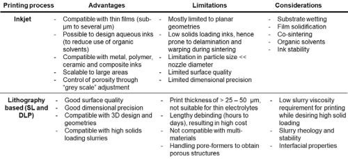
Table 1 - Comparison of the two main AM processes for printing SOECs and SOFCs.
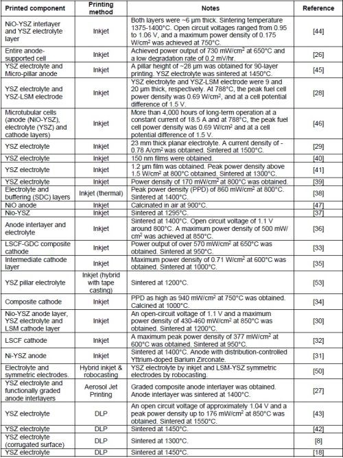
Table 2 – A summary of current reported work in literature.
4. Acknowledgements
This work is supported by the AESF foundation under the AESF Foundation Research Program and the US National Science Foundation (CMMI award number 2152732).
5. References
1. Achieving American Leadership in the Hydrogen Supply Chain, US Department of Energy, 2022.
2. High Temperature Electrolysis Manufacturing Workshop Summary Report, Hydrogen and Fuel Cell Technologies Office, U.S. Department of Energy, March 2022.
3. A. Hauch, et al., “Recent advances in solid oxide cell technology for electrolysis,” Science, 370 (6513), p. eaba6118 (2020).
4. Water Electrolyzers and Fuel Cells Supply Chain: Supply Chain Deep Dive Assessment, U.S. Department of Energy Response to Executive Order 14017, “America’s Supply Chains”, 2022.
5. C.L. Cramer, et al., “Additive manufacturing of ceramic materials for energy applications: Road map and opportunities,” Journal of the European Ceramic Society, 42 (7), 3049-3088 (2022).
6. J.C. Ruiz-Morales, et al., “Three dimensional printing of components and functional devices for energy and environmental applications,” Energy & Environmental Science, 10 (4), 846-859 (2017).
7. M. R. Weimar, L.A. Chick, D. W. Gotthold and G. A. Whyatt, Cost Study for Manufacturing of Solid Oxide Fuel Cell Power Systems, Pacific Northwest National Laboratory, contract DE-AC05-76RL01830, September 2013.
8. A. Pesce, et al., “3D printing the next generation of enhanced solid oxide fuel and electrolysis cells,” Journal of Materials Chemistry A, 8 (33), 16926-16932 (2020).
9. A. Bertei, et al., “Guidelines for the Rational Design and Engineering of 3D Manufactured Solid Oxide Fuel Cell Composite Electrodes,” Journal of The Electrochemical Society, 164 (2), F89-F98 (2016).
10. C.-C. Chueh and A. Bertei, “Thermo-mechanical analysis of 3D manufactured electrodes for solid oxide fuel cells,” Journal of the European Ceramic Society, 41 (1), 497-508 (2021).
11. L. Zouridi, et al., Advances in Inkjet-Printed Solid Oxide Fuel Cells,” Advanced Materials Technologies, 7 (7), 2101491 (2022).
12. L.J. Deiner, and T.L. Reitz, “Inkjet and Aerosol Jet Printing of Electrochemical Devices for Energy Conversion and Storage,” Advanced Engineering Materials, 19 (7), 1600878 (2017).
13. X.Y. Tai, et al., “Accelerating Fuel Cell Development with Additive Manufacturing Technologies: State of the Art, Opportunities and Challenges,” Fuel Cells, 19 (6), 636-650 (2019).
14. S.A. Rasaki, et al., “The innovative contribution of additive manufacturing towards revolutionizing fuel cell fabrication for clean energy generation: A comprehensive review,” Renewable and Sustainable Energy Reviews, 148, 111369 (2021).
15. X. Zhang, X. Wu and J. Shi, “Additive manufacturing of zirconia ceramics: a state-of-the-art review,” Journal of Materials Research and Technology, 9 (4), 9029-9048 (2020).
16. A. Ambrosi, R.R.S. Shi and R.D. Webster, “3D-printing for electrolytic processes and electrochemical flow systems,” Journal of Materials Chemistry A, 8 (42), 21902-21929 (2020).
17. P.A. Connor, et al., “Tailoring SOFC Electrode Microstructures for Improved Performance,” Advanced Energy Materials, 8 (23), 1800120 (2018).
18. B. Xing, et al., “Dense 8 mol% yttria-stabilized zirconia electrolyte by DLP stereolithography,” Journal of the European Ceramic Society, 40 (4), 1418-1423 (2020).
19. Yixiang Shi, Ningsheng Cai, Tianyu Cao and Jiujun Zhang, High-Temperature Electrochemical Energy Conversion and Storage: Fundamentals and Applications, CRC Press, 2018.
20. Y. Liu, et al., “Development of nickel based cermet anode materials in solid oxide fuel cells – Now and future,” Materials Reports: Energy, 1 (1), 100003 (2021).
21. V.J. Ferreira, et al., “5 kW SOFC stack via 3D printing manufacturing: An evaluation of potential environmental benefits,” Applied Energy, 291, 116803 (2021).
22. B. Shri Prakash, S. Senthil Kumar and S.T. Aruna, “Properties and development of Ni/YSZ as an anode material in solid oxide fuel cell: A review,” Renewable and Sustainable Energy Reviews, 36, 149-179 (2014).
23. M.F. Riyad, M. Mahmoudi and M. Minary-Jolandan, “Manufacturing and Thermal Shock Characterization of Porous Yttria Stabilized Zirconia for Hydrogen Energy Systems,” Ceramics, 5 (3), 472-483 (2022).
24. A. Brouzgou, A. Demin and P. Tsiakaras, “Interconnects for Solid Oxide Fuel Cells,” in Advances in Medium and High Temperature Solid Oxide Fuel Cell Technology, M. Boaro and A.A. Salvatore, Editors, Cham: Springer International Publishing, 2017; pp. 119-153.
25. Gunawan, Sulistyo and S. Iwan, “Progress in Glass-Ceramic Seal for Solid Oxide Fuel Cell Technology,” Journal of Advanced Research in Fluid Mechanics and Thermal Sciences, 82 (1), 39-50 (2021).
26. G.D. Han, et al., “Inkjet Printing for Manufacturing Solid Oxide Fuel Cells,” ACS Energy Letters, 5 (5), 1586-1592 (2020).
27. A.M. Sukeshini, et al., “Aerosol Jet® Printing of functionally graded SOFC anode interlayer and microstructural investigation by low voltage scanning electron microscopy,” Journal of Power Sources, 224, 295-303 (2013).
28. N.M. Farandos, T. Li and G.H. Kelsall, “3-D inkjet-printed solid oxide electrochemical reactors. II. LSM - YSZ electrodes,” Electrochimica Acta, 270, 264-273 (2018).
29. N .M. Farandos, et al., “Three-dimensional Inkjet Printed Solid Oxide Electrochemical Reactors. I. Yttria-stabilized Zirconia Electrolyte,” Electrochimica Acta, 213, 324-331 (2016).
30. A.M. Sukeshini, et al., “Inkjet Printing of Anode Supported SOFC: Comparison of Slurry Pasted Cathode and Printed Cathode,” Electrochemical and Solid-State Letters, 12 (12), B176 (2009).
31. H. Shimada, et al., “Electrochemical Behaviors of Nickel/Yttria-Stabilized Zirconia Anodes with Distribution Controlled Yttrium-Doped Barium Zirconate by Ink-jet Technique,” Journal of The Electrochemical Society, 159 (7), F360-F367 (2012).
32. G.D. Han, et al., “Fabrication of lanthanum strontium cobalt ferrite (LSCF) cathodes for high performance solid oxide fuel cells using a low price commercial inkjet printer,” Journal of Power Sources, 306, 503-509 (2016).
33. G.D. Han, et al., “Fabrication of Lanthanum Strontium Cobalt Ferrite–Gadolinium-Doped Ceria Composite Cathodes Using a Low-Price Inkjet Printer, ACS Applied Materials & Interfaces, 9 (45), 39347-39356 (2017).
34. C. Li, et al., “Green fabrication of composite cathode with attractive performance for solid oxide fuel cells through facile inkjet printing,” Journal of Power Sources, 273, 465-471 (2015).
35. N. Yashiro, T. Usui and K. Kikuta, “Application of a thin intermediate cathode layer prepared by inkjet printing for SOFCs.” Journal of the European Ceramic Society, 30 (10), 2093-2098 (2010).
36. M.A. Sukeshini, et al., “Ink-Jet Printing: A Versatile Method for Multilayer Solid Oxide Fuel Cells Fabrication,” Journal of the American Ceramic Society, 92 (12), 2913-2919 (2009).
37. M. Rosa, et al., “Printing of NiO-YSZ nanocomposites: From continuous synthesis to inkjet deposition,” Journal of the European Ceramic Society, 39 (4), 1279-1286 (2019).
38. C. Li, et al., “Thermal inkjet printing of thin-film electrolytes and buffering layers for solid oxide fuel cells with improved performance,” International Journal of Hydrogen Energy, 38 (22), 9310-9319 (2013).
39. R.I. Tomov, et al., “Direct ceramic inkjet printing of yttria-stabilized zirconia electrolyte layers for anode-supported solid oxide fuel cells,” Journal of Power Sources, 195 (21), 7160-7167 (2010).
40. C. Gadea, et al., “Aqueous metal–organic solutions for YSZ thin film inkjet deposition,” Journal of Materials Chemistry C, 5 (24), 6021-6029 (2017).
41. V. Esposito, et al., “Fabrication of thin yttria-stabilized-zirconia dense electrolyte layers by inkjet printing for high performing solid oxide fuel cells,” Journal of Power Sources, 273, 89-95 (2015).
42. S. Masciandaro, et al., “Three-dimensional printed yttria-stabilized zirconia self-supported electrolytes for solid oxide fuel cell applications,” Journal of the European Ceramic Society, 39 (1), 9-16 (2019).
43. L. Wei, et al., “A novel fabrication of yttria-stabilized-zirconia dense electrolyte for solid oxide fuel cells by 3D printing technique,” International Journal of Hydrogen Energy, 44 (12), 6182-6191 (2019).
44. D. Young, et al., “Ink-jet printing of electrolyte and anode functional layer for solid oxide fuel cells,” Journal of Power Sources, 184 (1), 191-196 (2008).
45. I. Jang and G.H. Kelsall, “Fabrication of 3D NiO-YSZ structures for enhanced performance of solid oxide fuel cells and electrolysers,” Electrochemistry Communications, 137, 107260 (2022).
46. W . Huang, et al., “High-Performance 3D Printed Microtubular Solid Oxide Fuel Cells,” Advanced Materials Technologies, 2 (4), 1600258 (2017).
47. A. Sobolev, P. Stein and K. Borodianskiy, “Synthesis and characterization of NiO colloidal ink solution for printing components of solid oxide fuel cells anodes,” Ceramics International, 46 (16, Part A), 25260-25265 (2020).
48. S. Pirou, et al., “Production of a monolithic fuel cell stack with high power density,” Nature Communications, 13 (1), 1263 (2022).
49. Y. De Hazan, et al., “High solids loading ceramic colloidal dispersions in UV curable media via comb-polyelectrolyte surfactants,” Journal of Colloid and Interface Science, 337 (1), 66-74 (2009).
50. S. Anelli, et al., “Hybrid-3D printing of symmetric solid oxide cells by inkjet printing and robocasting,” Additive Manufacturing, 51, 102636 (2022).
51. B. Dermeik and N. Travitzky, “Laminated Object Manufacturing of Ceramic-Based Materials,” Advanced Engineering Materials, 22 (9), 2000256 (2020).
52. R.I. Merino, et al., “Laser processing of ceramic materials for electrochemical and high temperature energy applications,” Boletín de la Sociedad Española de Cerámica y Vidrio, 61, Supp. 1, S19-S39 (2022).
53. F. Salari, et al., “Hybrid additive manufacturing of the modified electrolyte‐electrode surface of planar solid oxide fuel cells,” International Journal of Applied Ceramic Technology, 17 (4), 1554‐1561 (2020).
6. Past project reports
1. Quarter 1 (January-March 2022): Summary: NASF Report in Products Finishing; NASF Surface Technology White Papers, 86 (10), 17 (July 2022); Full paper: http://short.pfonline.com/NASF22Jul1 .
2. Quarter 2 (April-June 2022): Summary: NASF Report in Products Finishing; NASF Surface Technology White Papers, 87 (1), 17 (October 2022); Full paper: http://short.pfonline.com/NASF22Oct2 .
7. About the Principal Investigator for AESF Research Project #R-123

Majid Minary Jolandan is Associate Professor of Mechanical Engineering at The University of Texas at Dallas, in Richardson, Texas, in the Erik Jonsson School of Engineering. His education includes B.S. Sharif University of Technology, Iran (1999-2003), M.S. University of Virginia (2003-2005), Ph.D. University of Illinois at Urbana-Champaign (2006-2010) as well as Postdoctoral fellow, Northwestern University (2010-2012). From 2012-2021, he held various academic positions at The University of Texas at Dallas (UTD) and joined the Faculty at Arizona State University in August 2021. In September 2022, he returned to at UTD as Associate Professor of Mechanical Engineering. His research interests include additive manufacturing, advanced manufacturing and materials processing.
Early in his career, he received the Young Investigator Research Program grant from the Air Force Office of Scientific Research to design high-performance materials inspired by bone that can reinforce itself under high stress. This critical research can be used for aircraft and other defense applications, but also elucidate the understanding of bone diseases like osteoporosis.
In 2016, he earned the Junior Faculty Research Award as an Assistant Professor at the University of Texas-Dallas – Erik Jonsson School of Engineering.
* Corresponding author:
Dr. Majid Minary Jolandan
Department of Mechanical Engineering
The University of Texas at Dallas
800 West Campbell Road
Richardson, TX 75080-3021
Office: ECSW 4.355H
Phone: 972-883-4641
Email: majid.minary@utdallas.edu
Related Content
Plating Additively Manufactured Plastic Parts
Using electroplating to enhance the structural properties of 3D printed parts.
Read More5 Big Themes in Additive Manufacturing at Formnext Forum: Austin
As manufacturing advances with additive, the advance increasingly emphasizes these five themes.
Read MoreNASF/AESF Foundation Research Project #123: Electrochemical Manufacturing for Energy Applications – 8th Quarterly Report
The NASF-AESF Foundation Research Board selected a project on electrodeposition toward developing low-cost and scalable manufacturing processes for hydrogen fuel cells and electrolysis cells for clean transportation and distributed power applications. This report covers the 8th quarter of work (October-December 2023, continuing work on 3D printing anode support for solid oxide fuel cells and electrolyzers. Work involved the effect of sintering temperature on the amount of porosity and grain size in 3D printed yttria-stabilized zirconia (YSZ).
Read MoreNASF/AESF Foundation Research Project #123: Electrochemical Manufacturing for Energy Applications - 9th Quarterly Report
This NASF-AESF Foundation research project report covers the ninth quarter of project work (January-March 2024) at the University of Texas at Dallas. In this period, we followed our work on 3D printing anode support for solid oxide fuel cells, SOFC (or cathode for solid oxide electrolyzers, SOEC). We focused on the mechanical properties of 3D printed yttria-stabilized zirconia (YSZ) using a four-point bending test. We then conducted a statistical analysis to characterize the flexural strength of porous 3D printed YSZ. The full paper on the ninth quarter work can be accessed and printed at short.pfonline.com/NASF24June2.
Read MoreRead Next
A ‘Clean’ Agenda Offers Unique Presentations in Chicago
The 2024 Parts Cleaning Conference, co-located with the International Manufacturing Technology Show, includes presentations by several speakers who are new to the conference and topics that have not been covered in past editions of this event.
Read MoreEpisode 45: An Interview with Chandler Mancuso, MacDermid Envio Solutions
Chandler Mancuso, technical director with MacDermid Envio discusses updating your wastewater treatment system and implementing materials recycling solutions to increase efficiencies, control costs and reduce environmental impact.
Read MoreEducation Bringing Cleaning to Machining
Debuting new speakers and cleaning technology content during this half-day workshop co-located with IMTS 2024.
Read More



.jpg;maxWidth=300;quality=90)


