
NASF/AESF University Funded Research Transitioned to Industry: Practical Performance Improvements in Functional REACH-Compliant Trivalent Chromium Plating
This paper shows information learned from a NASF/AESF Foundation Research grant which has led to successful application. The work at the University of Houston (UH) is discussed – a technique developed to perform in-situ analysis of the stress of the chromium deposit from a REACH-compliant trivalent chromium electrolyte. An understanding of crack formation during plating has led the way to a means to avoid it. Faraday Technology Inc. scaled-up and optimized the same process through support from the U.S. Army. The results enabled significant chromium coating performance enhancements, matching the wear index of conventional Cr deposits from hexavalent baths.


by
Kamyar Ahmadia,* Rajeswaran Radhakrishnanb, Jing Xub, Stephen T. Snyderb, Mark G. Feathersc, Michael L. Johnsonc, Timothy D. Hallb, E. Jennings Taylorb, Maria Inmanb, Stanko Brankovica
a Material Science Program and Electrical and Computer Engineering, University of Houston, Houston, Texas, USA
b Faraday Technology Inc. Englewood, Ohio, USA
c United States Army Aviation and Missile Command, 5300 Martin Road, Redstone Arsenal, Alabama, USA
Editor’s Note: This paper relates the practical application of information learned from the NASF/AESF Foundation Research program toward functional REACH-compliant trivalent chromium technology. A printable pdf version of this paper can be accessed and printed HERE.
ABSTRACT
This paper discusses the use and critical practical learning from university scientific research approaches and the transition of those observations to practical part production at an industrial scale. Specifically, we will discuss the work from the University of Houston (UH) (Houston, TX) who developed a technique to perform in-situ analysis of the stress of the chromium deposit from a Registration, Evaluation, Authorization and Restriction of Chemicals (REACH)-compliant trivalent chromium electrolyte. The project was funded by a NASF/AESF Foundation** research grant and the State of Texas, while Faraday Technology Inc. (Englewood, OH) strove to scale and optimize the same chromium deposit from the same electrolyte through support from the U.S. Army in a 150-gallon industrial scale tank. The collaboration and observations from their combined work enabled significant chromium coating performance enhancements, such as a reduction in the coating wear index (Taber Abrasion; ASTM D4060) from 3 to 1.2, essentially matching the wear index of conventional chromium deposits from hexavalent chromium [Cr(VI)] electrolytes.
Introduction
All maintenance facilities are under pressure to reduce or eliminate the use of hexavalent chromium [Cr(VI)] chemistries. Traditional chromium plating releases a mist of highly corrosive droplets that poses a risk to process operators. Hexavalent chromium has been implicated in long-term health effects, including cancer, and is listed as a known human carcinogen by the International Agency for Research on Cancer and the American Conference of Governmental Industrial Hygienists. The OSHA Personal Exposure Limit for Cr(VI) was lowered in 2006 from 52 to 5 μg/m3. A new Threshold Limit Value (TLV) of .0002 mg/m3 for inhalable hexavalent chromium compounds, as well as a Short-Term Exposure Limit (STEL) of 0.0005 mg/m3, has been established. Any further reduction in Cr(VI) exposure limits will continue to make the use of Cr(VI) processes less sustainable or practical.
Hexavalent chromium, in all its forms, has been listed as a Substance of Very High Concern (SVHC) under the European Union's (EU) Registration, Evaluation, Authorization & Restriction of Chemicals (REACH) and has been given a sunset date of 21 September 2021. This means that 18 months prior to the sunset date (i.e., 21 March 2020), the manufacture of these products must cease in the EU. Therefore, OEMs working in the global market must find alternatives; otherwise, they will be unable to compete. As a result, lower tiered supply chains may become obsolete if demand for Cr(VI)-containing processes is reduced. The urgency of this issue was underscored by a memorandum from the Under Secretary of Defense, referring to the need to minimize or eliminate the use of Cr(VI) as an "extraordinary situation," requiring DoD to "go beyond established hazardous materials management processes" and to "more aggressively mitigate the unique risks to DoD operations now posed by” Cr(VI).
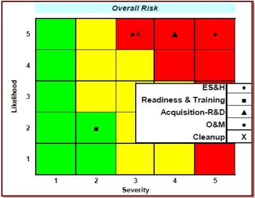
Figure 1 - Overall risk cube for Cr(VI) showing the risk levels associated with sub-functional areas.
Figure 1 graphically shows the results of the "Impact Assessment for Cr(VI) Compounds" from the Deputy Under Secretary of Defense for Installations and Environment Emerging Contaminants Directorate. Note that all aspects, with the exception of "Readiness & Training," are highly likely and range from moderate to high severity. Additional risks involve compliance costs and regulatory violations. The DoD has established 48 CFR Part 223 in the Defense Federal Acquisition Regulation Supplement, "Minimizing the Use of Materials Containing Hexavalent Cr(VI) Chromium." Risk assessment by the EPA could further restrict regulatory limits, as per 40 CFR 63, Subpart N, National Emission Standards for Hazardous Air Pollutant Emissions: Hard and Decorative Chromium Electroplating and Chromium Anodizing Tanks. The Clean Water Act sets effluent limits on pollutants per 40 CFR 433 (Metal Finishing) and 40 CFR Part 413 (Electroplating). The Resource Conservation and Recovery Act also targets specific wastes. Army Environmental Requirements and Technology Assessment requirement PP-2-02-04, Toxic Metal Reduction in Surface Finishing of Army Weapon Systems, has been established, and this project will address that requirement by eliminating Cr(VI) in the hard chromium plating process. The need to reduce/eliminate Cr(VI), along with other toxic metals, was detailed in the report Reduction of Toxic Materials in Army Surface Finishing Processes: Environmental Requirement and Technology Assessment, completed by AMCOM G-4 in 2012.
Several alternative technologies, among them high velocity oxy-fuel (HVOF) spray coating, have undergone extensive evaluation, some for a decade. Yet Cr(VI) electroplating is still carried out at many facilities. One insurmountable problem with HVOF and other potential spray technologies is adapting them to applications involving inside diameters and other geometries where no direct line-of-sight exists between the surface to be coated and the applicator. Facilities are understandably reluctant to incur the significant capital costs and undertake the massive qualification and training programs required to institute a partial solution. As a result, Cr(VI) plating, even for applications where spray coating would provide an acceptable alternative, is still firmly established throughout the industrial base.
The following sections provide a brief introduction to the pulse/pulse reverse electroplating approach used by the University of Houston (UH) and the key observations and their effect on scale-up at Faraday Technology.
Pulse / Pulse Reverse Electroplating
During Cr(III) plating, chromium is deposited and hydrogen is evolved at the cathode, as described in the following reactions:
Cr+3 + 3e− ⇒ Cr (Φo = - 0.74 VSHE) (1)
2H+ + 2e− ⇒ H2 (Φo = 0 VSHE) (2)
The current efficiency for chromium plating from a Cr(III) bath is usually below 20%. At least 80% of the current is used for the hydrogen evolution reaction and, as a result, the pH near the cathode surface increases dramatically, and chromic hydroxide (Ksp = 5.4 × 10⁻³¹) precipitates in the high pH boundary layer near the cathode. The precipitated chromic hydroxide can then be included within the deposited chromium across the cathode surface and its density can increase as the plating time and pH increase. This promotes an increase of cathode polarization, a further decrease of chromium plating efficiency (i.e., an increase in the hydrogen evolution reaction) and an increase of impurities in the plating film. All of these factors retard the normal growth of crystals in the plating film, leading to the inhibition of chromium plating as the evolution of hydrogen continues. The precipitation of chromic hydride / hydroxide species at the cathode also results in surface cracks and reduces the hardness and brightness of the chromium coating. Faraday's approach deals with overcoming this hydrogen evolution problem and dissolution / desorption of the precipitates by utilizing pulse / pulse-reverse fields during electroplating.
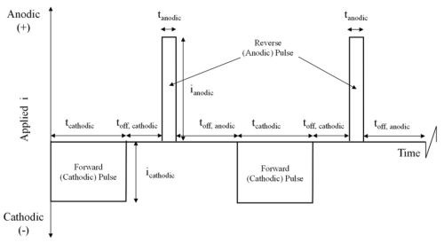
Figure 2 - Schematic diagram of a generic pulse / pulse-reverse waveform.
The process utilizes pulse and pulse-reverse waveforms. Figure 2 is an example of a pulse / pulse-reverse waveform, consisting of a cathodic (forward) pulse followed by an anodic (reverse) pulse and a relaxation period (off-time). The cathodic peak current (ic), cathodic on-time (tc), anodic peak current (ia), anodic on-time (ta), and the off-time (to) are individual variables for process control. The sum of the cathodic on-time, anodic on-time and off-time is the period of the waveform and the inverse of the period is the frequency. The cathodic duty cycle (γc ) is the ratio of the cathodic on-time to the period, and the ratio of the anodic on-time to the period is the anodic duty cycle (γa). The frequency and duty cycles are additional variables for process control. The average current density (iaver) or electroplating rate is given by:
iaver = icγc - iaγa (3)
Just as there are infinite combinations of height, width and length to obtain a given volume, in pulse and pulse-reverse processes there are unlimited combinations of peak current densities, duty cycles and frequencies to obtain a given electrodeposition rate. By controlling the cathodic on-time, anodic on-time, off-time and the cathodic and anodic peak currents, precise control of the electrodeposition process is achieved and consequently the properties of the resulting deposit may be controlled or fine-tuned for a specific application. In conventional direct current (DC) electroplating, the current is turned on and held for the duration of the process. By interrupting this constant stream of current, as in the pulse / pulse-reverse process, one may achieve results not possible with conventional DC electroplating, such as deposit property control and elimination of adverse side reactions, such as hydrogen evolution, which may become co-deposited with chromium, affecting the nature of the deposit and resulting in samples with inadequate wear properties.
Prior Work on Functional Cr(III) Plating
In previously reported work we accomplished the following milestones:
- Plated from a trivalent chromium sulfate bath where the consumable was in the price range of chromic acid,1
- Simplified the bath chemistry using pulse reverse waveforms,1
- Increased the chromium plating thickness to 250 μm,1
- Maintained a plating rate similar to that of Cr(VI),1
- Determined the maximum diffusion layer thickness for plating from a trivalent chromium sulfate bath,2
- Determined the acceptable range for achieving bright plating,2
- Replated chromium on chromium,2
- Displayed superior corrosion resistance compared to laser-coated surfaces,3
- Achieved a suitable chromium distribution for pump rotor wear tests at a manufacturer,4
- Achieved equal or better wear resistance compared to a Cr(VI) deposit against hardened steel,4
- Demonstrated similar salt spray corrosion resistance,5
- Developed a surface pretreatment procedure,5 and
- Demonstrated nominally identical bend to break adhesion as ([Cr(VI)] deposits.5
Current Work on Functional Cr(III) Plating
In the current program Faraday Technology is collaborating with UH (who is funded through AESF Foundation Project #R-118). Faraday is working to transition the university's observations to an industrial scale in support of the United States Army Aviation and Missile Command (AMCOM) and the U.S. Army Combat Capabilities Development Command, Environmental Technology Acquisition Program, in order to improve the functionality of the chromium deposits produced by the pulse / pulse-reverse process, using a commercial boric acid-free REACH compliant Cr(III).*** The evaluation criteria include:
- Thickness per AMS 2460, 3.4.1
- Porosity per AMS 2460, 3.4.4
- Adhesion per AMS 2460, 3.4.2
- Surface roughness and morphology
- H2 embrittlement per ASTM F519
- Hardness AMS 2460, 3.4.3
- Corrosion resistance per ASTM B519 (Salt Spray)
- Wear
- Taber Abrasion per ASTM D4060
- Ball on Disc per ASTM G133
- Oscillation
- Amp-hr solution analysis for Cr(VI)
- Fatigue axial tension per ASTM E466 and ASTM E468
- Rotating beam tests per ISO 1143 and ASTM E468.
AESF Funded University Observation
As published within multiple AESF reports (Project #R-118)6, UH designed and built an in-situ stress measurement tool based on a cantilever bending method. The working principle of this setup is based on the cantilever (working electrode) bending during the film growth which can be directly associated to the internal stress in the film.7 The movement of the cantilever is measured by reflection of a laser beam from the cantilever on a position sensitive detector (PSD). Figure 3 schematically shows the cantilever movement in cases of compressive and tensile stresses in the film, where it bends outward and inward, respectively. This movement is measured by reflection of a laser beam from backside of the cantilever on a PSD.
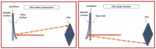
Figure 3 - Effect of deposition on a cantilever and its associated PSD reflection for compressive (L) and tensile (R) stress in the film during electrodeposition processes.
The initial critical result from this NASF/AESF Foundation-funded activity was a stress profile comparison as a function of thickness of a sample plated from the conventional Cr(VI) electrolyte to that of one prepared from the environmentally benign trivalent chromium electrolyte.*** Specifically, Fig. 4 shows the coating stress profile observed during Cr(VI) plating (L) has a large tensile stress form as the first few microns are deposited. As deposition progresses, discontinuous crack formation / stress relief occurs during plating. On the other hand, the trivalent chromium plating system (R) has a large compressive stress, with crack formation / stress relief after plating, a function of time and temperature during a post-plating bake. This key difference is the reason plating from each electrolyte requires different challenges in order to achieve the desired coating performance properties.
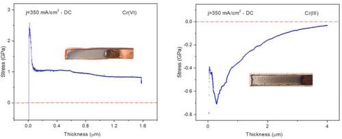
Figure 4 - Shows a comparison of the stress profile observed within the in-situ stress measurement rig at UH for deposits from (L) a conventional Cr(VI) electrolyte and (R) an environmentally benign trivalent chromium electrolyte.
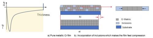
Figure 5 - An inclusion-based conceptual model of how compressive stresses form during the deposition of Cr from the trivalent chromium electrolyte.
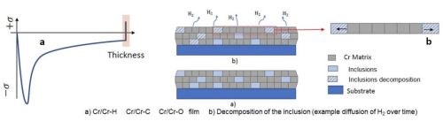
Figure 6 - A conceptual model of the decomposing inclusion within the compressive film causing a tensile relaxation.
Considering the resounding difference in the chromium deposits, measured stress during deposition requires consideration in the mechanism that is causing the compressive stress. One model for this stress profile is shown in Fig. 5, where the compressive stress during deposition is directly a result of inclusions of carbon, hydroxides and particularly hydrides being included in the deposit within its thickness. These inclusions cause an inherent compressive stress on the coating. Additionally, the inclusions formed during the deposition process are unstable and easily degrade when given adequate time outside of the deposition conditions, causing a tensile relaxation as illustrated in Fig. 6. Understanding control of this tensile relaxation mechanism was the next critical understanding established by the NASF/AESF Foundation-funded work.
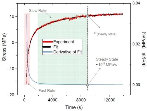
Figure 7 - Typical stress relaxation transient after deposition of a chromium film from a Cr(III) electrolyte (red line); derivative (blue line) of the smoothed fit (dashed line) represents relaxation rate transients.
Specifically, UH studied the relaxation stress of the films deposited with various waveforms and evaluated the effect of including off-times selectively within the deposition process. Figure 7 indicates a typical tensile relaxation transient curve after a direct current (DC) deposition (red line). The tangent of the curve at each point of time represents the relaxation rate at that moment. Accordingly, the rate of relaxation as a function of time (blue line) can be calculated by first derivative of the smoothed fit (dashed line) of the relaxation transient curve. As shown in Fig. 7, the rate of relaxation at the early post-deposition stage is relatively fast, when accumulated and unstable inclusions start to decompose. Over time, the content of the unstable inclusions in the film and thus the rate of relaxation decrease. Therefore, the value and rate of relaxation stress can be used as a means to better understand the content of incorporated inclusions in the film and their degradation progress after the deposition.
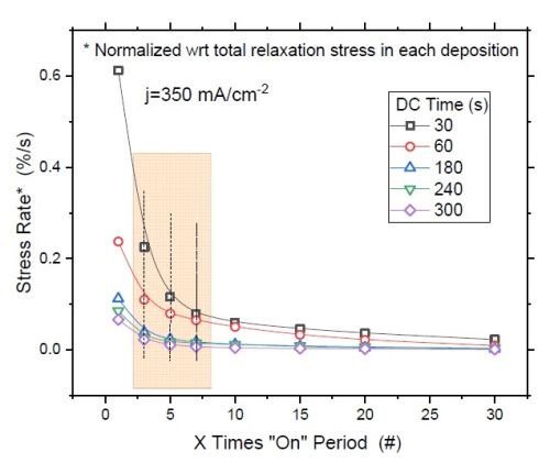
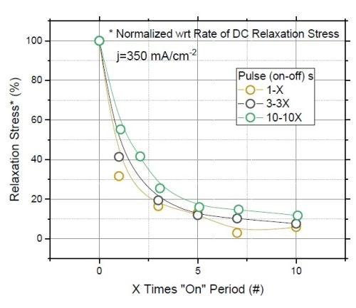
Figure 8 - (a) F/w rate transient of films deposited with various "on" times (thickness); (b) normalized tensile relaxation rate of films deposited with various pulses immediately after deposition.8
Figure 8(a) shows the relaxation rate transient for DC deposited films at various deposition times (thickness). This graph shows that independent of the deposition length (X), the relaxation rate dramatically slows down after seven times the deposition length (7X). This suggests that the majority of hydride inclusions are decomposed within 7X. In other words, utilizing pulse currents where toff is more than 5X can effectively reduce the hydride/hydroxide content of the film during the deposition stage. Figure 8(b) shows the normalized rate of stress relaxation immediately after the deposition for the pulse current (PC) deposited films with an identical thickness but various pulse lengths and duty cycles. The initial rates of relaxation were obtained by the tangent of the relaxation curve in the first few seconds after each deposition. The higher rate at the onset of the relaxation indicates more accumulated inclusions in the film, which start to decompose instantly after the deposition. The graph shows that independent of the deposition pulse length (Xs), whether it is 1, 3 or 10 seconds, the initial rate of relaxation follows the same trend as a function of the "off" time. Employing pulses with "off" times longer than 7X has a small gain and will not considerably reduce the rate of relaxation. This data suggests that using pulses with more than 7Xs "off" only slightly helps in reduction of hydride content in the film, which is compatible with the conclusion from Figure 8(a).
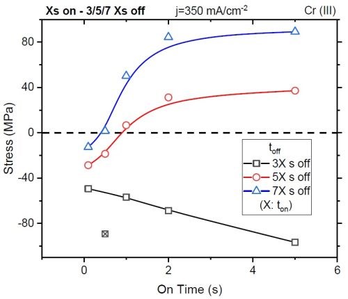
Figure 9 - Total stress observed in the coating after applying waveform conditions with controlled on-times and specified off-times.
Reorganization of these results can give a coating measured stress after depositing a nominally identical film thickness at various forward pulse operating conditions. Specifically, as shown in Fig. 9, the stress in the coating (<100 nm) changes as a function of the deposition on-time (x-axis), particularly for the short ton, where non-faradaic currents are significant, and the duration of the off-time with each given on-time, where the off-time equals 3, 5, or 7 times (black, red, and blue, respectively) that of the on-time.
This work found that, for every layer of chromium deposited, an off-time approaching 5 to 7 times that of the duration of the on-time was required to eliminate the stress in the deposit. With this result, UH postulated that the stress in the deposit was a function of incorporation and the decomposition of inclusions within the deposit, such as CrH, CrOH, CrO, etc. These observations set the stage for some of the key directions for coating industrialization at Faraday.
Industry Observation
Faraday has been working to develop a process to apply functional chromium coatings from a trivalent chromium electrolyte for a number of years and has successfully established a plating facility with a 150-gallon tank capacity (Fig. 10) that was utilized to demonstrate the potential to meet or surpass many of the specified industrial performance standards by optimizing the waveform conditions during the deposition process, as shown in Table 1. The process robustness has been improved such that over 1,400 A-hr of use has been successfully applied to the bath with minimal variation in performance. However, we have noted specific limitations in the cross-sectional microstructure and wear index, due to thru-macrocracks in the coating after the deposition and post-embrittlement relief processes. We had postulated an expansion in the coating, but until confirmation by the AESF work discussed above, we did not have a working mechanism for the controlling factors pertaining to the formation of these macrocracks.
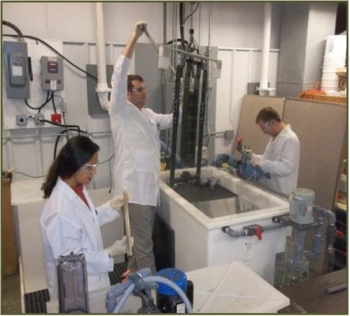
Figure 10 - Pre-production 150-gallon plating cell at Faraday.
Table 1 - Summary of chromium coating performance from a trivalent chromium electrolyte.
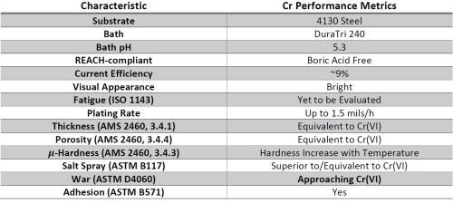
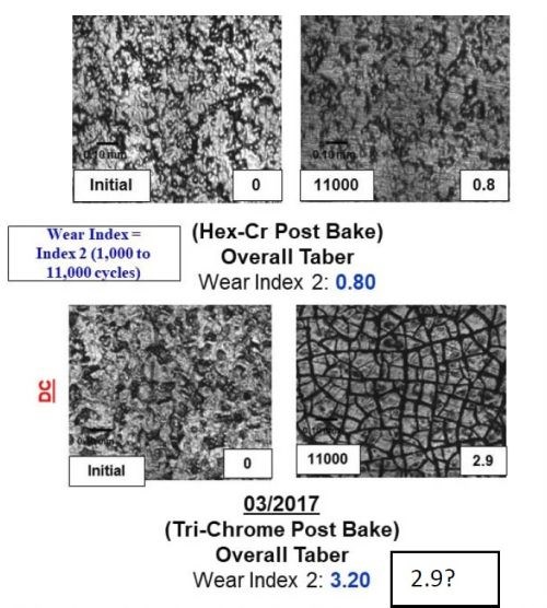
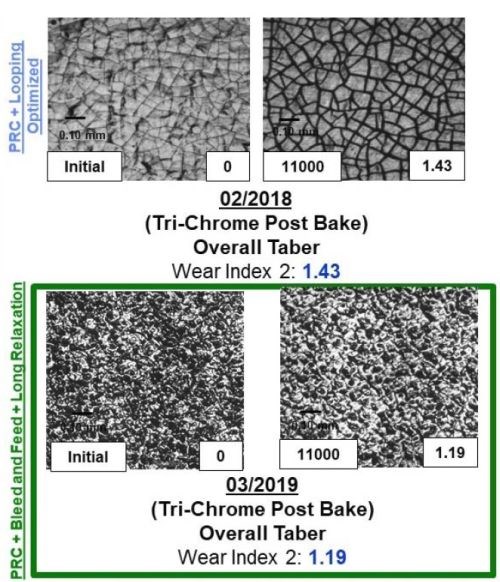
Figure 11 - A comparison between the surface, wear track and wear index as a function of time throughout the program for both samples plated from the Cr(VI) and trivalent chromium electrolytes.
The majority of the work at Faraday over the past two years has focused on utilizing the Taber Abrasion wear index (WI) number measured using the ASTM D4060 test to rapidly measure the effect of the various electrodeposition processing conditions studied. Through our optimization trials, we specifically observed that effect by evaluating the wear track formed during the 11,000 cycles of the wheel. The data in Fig. 11 demonstrates the improvement in the WI, going from 3.2 to 1.2 over the course of the Faraday and UH development programs, as well as the wear track microstructure. It compares the WI and wear track for a Cr(VI) baseline sample. The images in Fig. 11 show both the plated surface (Left of each set) and the surface in the wear track after the completion of ASTM D4060 (Right of each set).
By comparing the wear track of the Cr(VI) coated samples (Top left) to the trivalent chromium plated wear track, we observed an exfoliation of the surface that formed during the analysis, likely due to the tensile relaxation post deposition. The data shows the dramatic improvement in the wear track as a function of the electrolyte and plating optimization trials undertaken and the new learning obtained from all of the combined synergistic activities going from 3.2 to 1.4 to 1.2 over the course of the program. Faraday's technique to reduce crystal size is (1) applying pulse reverse current operation, (2) looping, a technique to create layers within the coating, and (3) using long relaxation times, representing the times associated with the learning obtained from the UH work.
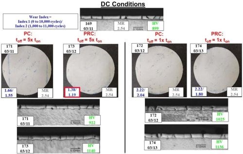
Figure 12 - Comparison of the WI, microstructure, ferroxyl cyanide porosity, hardness and deposition conditions.
This dramatic improvement in the deposit properties is further illustrated in Fig. 12, which shows the difference between pulse reverse current (PRC; which consists of cathodic, anodic and off-times) and pulse current (PC; which consists of only cathodic and off-times) as well as the effect of the off-time duration (as a multiple of the cathodic time during each pulse) compared to direct current processing. When comparing the data, we see a measurable improvement in the WI (wear index; blue in the bottom left corner of each image) when utilizing PC or PRC waveforms instead of direct current (DC) conditions (Top; 2.54). We see an increase in the micro-hardness (green in the bottom right corner of each image) and a desired decrease in the ferroxyl cyanide porosity (AMS 2460 3.4.4) and WI with the use of PRC conditions instead of PC conditions. These results could be related to obtaining better control of the degradation of the inclusion mechanism as discussed previously. Regardless, this data clearly illustrates the usefulness of the combined synergistic activities.
Conclusions
This activity was designed to leverage synergistic activities with commercial and government clients, chemical suppliers and collaborators to advance the trivalent chromium process technology as a boric acid-free REACH complaint and environmentally benign chromium plating process. Faraday (funded by the U.S. Army) worked closely with UH (funded by National Association for Surface Finishing Resource Grant Program) and Coventya (internally funded) to understand the relationship between the chromium coatings performance and the conditions utilized during of the trivalent chromium deposition process. These synergistic programs combined to demonstrate:
- Wear Index of the coating as low as 1.2
- Electrolyte stability to over 40 weeks, 320 A-hr/L, or 191 kA-hr
- Coating material properties that meet or exceed current standard matrices, with respect to: wear (ASTM D4060), corrosion resistance (ASTM B117), μ-hardness (ASTM 2460, 3.4.3), porosity (ASTM 2460, 3.4.4), adhesion (ASTM B571), thickness (ASTM 2460, 3.4.1) and fatigue (ISO1143)
- An initial mechanistic understanding of the coating properties with respect to plating conditions, for instance: (1) direct current deposited chromium from a trivalent electrolyte has a compressive stress, (2) application of pulse reverse currents improves coating hardness and wear properties, (3) use of long off-times improve coating microstructure and (4) control post deposition embrittlement relief treatment improves microstructure.
These results demonstrate the potential to meet or exceed the targeted performance properties but also identify other challenges that must be overcome prior to industrialization of this technology. Future work is directed towards a further refinement of: (1) the weekly or daily electrolyte maintenance and measurement protocols, (2) the pulse parameters, such as pulse duration during the pulse plating process and (3) the post deposition embrittlement relief treatments. The work may also require the development of new standard best practices tailored specifically to trivalent chromium plating for functional applications.
Acknowledgement
This study is supported by the NASF/AESF Foundation Research Project #R-118, U.S. Army (Contract No. W911NF1920329) and commercial sources. Coventya Inc. is providing the boric acid-free REACH compliant chemistry that was used for this work at Faraday and UH. The financial support of Faraday Technology, Inc. corporate research and development is also gratefully acknowledged.
References
1. R.P. Renz, J.J. Fortman, E.J. Taylor & M.E. Inman, “Effects of Bath Chemistry, Solution Hydrodynamics and Electrical Mediation on Trivalent Chromium Plating,” in Proc. AESF SUR/FIN 2001, NASF, Washington, DC, 2001; pp. 637-645.
2. R.P. Renz, J.J. Fortman, E.J. Taylor & M.E. Inman, “Electrically Mediated Process for Functional Trivalent Chromium to Replace Cr(VI) Chromium: Scale-up for Manufacturing Insertion,” in Proc. AESF SUR/FIN 2002, NASF, Washington, DC, 2002; pp. 395-407; also Plating & Surface Finishing, 90 (6), 52 (2003).
3. R.P. Renz, J.J. Fortman & E.J. Taylor, “Electrically Mediated Process for Functional Trivalent Chromium to Replace Cr(VI) Chromium: Scale-Up for Manufacturing Insertion,” in Proc. AESF SUR/FIN 2003, NASF, Washington, DC, 2003; pp. 330-344.
4. R.P. Renz, J.J. Fortman & E.J. Taylor, “Plating from a Functional Trivalent Chromium Bath to Replace Cr(VI) Chromium Plating,” in Proc. AESF SUR/FIN 2004, NASF, Washington, DC, 2004; pp. 506-520.
5. http://www.nmfrc.org/pdf/psf2010/2010-11-12-42.pdf .
7. Janssen, Guido CAM, et al. "Celebrating the 100th anniversary of the Stoney equation for film stress: Developments from polycrystalline steel strips to single crystal silicon wafers," Thin Solid Films, 517 (6), 1858-1867 (2009).
8. Ahmadi, K., and Stanko R. Brankovic. "13th and 14th Quarterly Report January-June 2019 AESF Research Project# R-118 Crack Formation during Electrodeposition and Post-deposition Aging of Thin Film Coatings," (2019); and preceding reports listed therein; https://www.pfonline.com/articles/crack-formation-during-electrodeposition-and-post-deposition-aging-of-thin-film-coatings---13th-14th-quarter-report .
About the authors

Kamyar Ahmadi is a doctoral student in Materials Engineering program at the University of Houston (UH). He obtained B.Sc. in Materials Science and Engineering from Iran University of Science and Technology (IUST) in 2014 before he joined UH. His research interests are thin film deposition and electrochemical fabrication of functional materials.

Rajeswaran Radhakrishnan is a Principal Scientist at Faraday Technology Inc. He received his B. Tech. in Chemical and Electrochemical Engineering from Central Electrochemical Research Institute, India (2009) and a Ph.D. in Materials Science and Engineering from Clarkson University, Potsdam, NY (2015). He is currently working within Faraday’s electropolishing and deposition portfolios; specifically, on electropolishing of passive alloys and electrodeposition of trivalent chromium coatings.

Jing Xu is a Principal Scientist at Faraday Technology Inc. She received her B.S. from Ludong University, Master’s degree from Nanjing University and her PhD. from Case Western Reserve University in Chemistry (spectroelectrochemistry) in 2015. Dr. Xu joined Faraday at 2016 and has successfully carried out research in a wide range of electrochemical engineering programs, e.g., functional coating material development (Tri-Cr and Cr alloys, Ni and Ni alloys, Cu, etc., on different substrates, e.g., SS4130, SS316, SS410, SS441, Si, Al T6061, Cu, Inconel 718), surface pretreatment (e.g., Al alloy T6061) and electrocatalysis.
Stephen T. Snyder is a Senior Research Engineer at Faraday Technology, Inc. He received his B.E. degree in Chemical Engineering from the University of Dayton and his M.S. degree from Purdue University in Materials Engineering. Mr. Snyder implements the engineering, design and fabrication of prototype instruments at the Faraday facility.

Mark G. Feathers is an employee with the U.S. Army Aviation and Missile Command, Redstone Arsenal, AL and serves as the Program Manager supporting environmentally sustainable coatings and processes. He currently leads a program to eliminate the use of hexavalent chromium from aviation depot and maintenance activities found in metal surface treatment processes, organic coatings and adhesive/sealant applications. Mr. Feathers is currently the Government Technical Monitor for the Faraday Trichrome Plating effort.

Michael L. Johnson is a materials engineer at Torch Technologies, Inc., and has been working with the Army Aviation & Missile Command, Environmental Group, since 2009. Prior to that, he obtained a B.Cer.E. degree from the Georgia Institute of Technology in 1990, and then worked in the fiber optics and transportation industries, as well as academia, for a total of 19 years.

Dr. Timothy D. Hall is the Laboratory Manager at Faraday Technology Inc. He received his B.S. in Chemical Engineering and Mathematics from West Virginia University (Morgantown, WV) in 2003, his M.S. and Ph.D. in Chemical Engineering from the University of Notre Dame (Notre Dame, IN) in 2006 and 2007, respectively. Dr. Hall was part of a team that received a 2011 R&D 100 Award, 2013 green chemistry award, and was a 2016 R&D 100 Award finalist in both plating and surface finishing electrochemical technologies. He has been a significant contributor to work that has led to six patents and numerous pending patent applications.

Dr. E. Jennings Taylor uniquely blends 40+ years entrepreneurial business experience with demonstrated skills in technology innovation and intellectual asset analysis. Prior to forming Faraday, Dr. Taylor held positions at Giner, Inc. as the Manager of Fuel Cell Research (1982-1985), and at Physical Sciences where he held numerous positions including the Manager of Electrochemical Technologies (1985-1991). In 1991, EJ left Boston to form Faraday Technology, Inc. He successfully secured start-up funding and from 1991-1997 served as the Principal Investigator on many of Faraday’s early research projects. In 1997, Dr. Taylor shifted his emphasis from research to strategic corporate direction and technology portfolio management. In order to facilitate the development of an intellectual property portfolio, he studied to become a Patent Agent and in February, 2003 was granted the status of registered agent with the US Patent and Trademark Office. Dr. Taylor applies this skill to develop patent portfolios that can benefit potential customers. EJ is well recognized in both the professional and business community. He is co-chair of the Technical Advisory Committee for SURFIN/NASF, Chair of the NASF/AESF Foundation Reserch Board, a past Treasurer of the Electrochemical Society, and a past Chair of the SBIR Advisory Board of the National Science Foundation.

Dr. Maria Inman is the Research Director at Faraday. Dr. Inman leads Faraday’s research and development function. In addition to providing day to day direction to the science and engineering staff at Faraday, Dr. Inman has served as Principal Investigator on millions of dollars worth of government and commercially-funded projects and serves as an integral member of Faraday’s internal strategic planning and IP management group. Dr. Inman has been on staff at Faraday for 26 of its 30 years in business.

Dr. Stanko R. Brankovic is a Professor in the Electrical & Computer Engineering and Chemical & Biomolecular Engineering Departments, as well as Associate Director, Center for Integrated Bio and Nanosystems at the University of Houston, Houston, Texas. He holds a B.E. in Chemical and Biochemical Engineering from the University of Belgrade, Serbia (1994) and a Ph.D. in the Science and Engineering of Materials from Arizona State University, Tempe, AZ (1999). He is active in many professional societies, including serving as Chair and member of the Electrodeposition Division Executive Committee of The Electrochemical Society (2006‐present) and as the Chair of the Electrochemical Material Science Division, The International Society of Electrochemistry (2015‐2017). His research interests include electrodeposition, thin films, electrocatalysis, sensors, corrosion and electrochemical material science and nanofabrication.
* Corresponding author:
Dr. Timothy D. Hall
Laboratory Manager
Faraday Technology
315 Huls Drive
Clayton, OH 45315
E-mail: timhall@faradytechnology.com
ORCID ID: 0000-0002-4756-0828
**National Association for Surface Finishing/American Electroplaters and Surface Finishers Foundation, 1800 M Street, Suite 400S, Washington, DC 20036; www.nasf.org.
*** DuraTri 240 Trivalent Hard Chromium, Coventya, Inc., 4639 Van Epps Road, Brooklyn Heights, OH 44131.


Related Content

Electroplating in the Context of Worldwide Nanotechnology Initiatives: A Heritage Paper
In the first part, a summary is presented on recently established nanotechnology initiatives in various countries around the world. Program funding levels and core activities will be compared to provide a basis for assessing business opportunities for various industries. The second part of the paper looks at specific examples of nanostructures made by electrochemical methods currently at various stages in their development, or already in use.
Read More
Take Full Advantage of Industry Events
As travel plans ramp up for the year, what industry events will you attend? Products Finishing offers a quick look at some of the upcoming opportunities for 2024.
Read More
Highlights from SUR/FIN 2023
Products Finishing offers a recap of some of the topics that were top of mind at the SUR/FIN 2023 finishing industry trade show.
Read More
Read Next

Education Bringing Cleaning to Machining
Debuting new speakers and cleaning technology content during this half-day workshop co-located with IMTS 2024.
Read More
Delivering Increased Benefits to Greenhouse Films
Baystar's Borstar technology is helping customers deliver better, more reliable production methods to greenhouse agriculture.
Read More
Episode 45: An Interview with Chandler Mancuso, MacDermid Envio Solutions
Chandler Mancuso, technical director with MacDermid Envio discusses updating your wastewater treatment system and implementing materials recycling solutions to increase efficiencies, control costs and reduce environmental impact.
Read More