Reducing Rinse Water Use
Conductivity control systems can help you decrease rinse water use, wastewater generation, wastewater treatment system chemical use and sludge generation...
The Merit Partnership is a joint venture between U.S. EPA Region 9, state and local regulatory agencies, private sector industries and community representatives. The partnership was created to promote pollution prevention (P2), identify P2 technology needs and accelerate P2 technology transfer within various industries in southern California. One of these industries is metal finishing, which is represented in the Merit Partnership by the Metal Finishing Association of Southern California (MFASC). Together, MFASC, EPA Region 9 and the California Manufacturing Technology Center (CMTC) established the Merit Partnership P2 Project for Metal Finishers. This project involves implementing P2 techniques and technologies at metal finishing facilities in southern California and documenting and sharing results. Technical support for this project is provided by Tetra Tech EM Inc. The project is funded by the Environmental Technology Initiative and EPA Region 9 and is implemented, in part, through CMTC by the National Institute of Standards and Technology.
Rinse operations significantly impact product finishing and plating operations by removing concentrated process solutions from part surfaces and minimizing dragin to subsequent operations. At most finishing facilities, water continuously flows through rinse tanks to provide proper rinsing. However, many facilities use more rinse water than necessary, which results in high water bills and wastewater treatment costs.
During finishing, as parts are removed from a process bath and dipped into a rinse tank, the concentrations of chemicals in the rinse water increase, thereby increasing rinse water conductivity. Conductivity control systems monitor the conductivity of the rinse water to maintain chemical concentrations at levels that provide adequate rinsing and prevent excessive dragin to subsequent process tanks. Conductivity control systems reduce water use by adding water to rinse tanks only when necessary instead of continuously.
Conductivity control systems
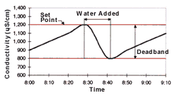
A conductivity control system consists of three main components: a conductivity sensor; a conductivity analyzer; and a solenoid valve (see Figure 1). The conductivity sensor is a probe placed in the rinse tank to measure rinse water conductivity. The conductivity analyzer is the signal processing unit that controls the system. This processing unit receives input from the sensor and determines rinse water conductivity. It features a programmable or adjustable set point and deadband. The deadband is the conductivity range within which the solenoid valve will remain open after being activated by the analyzer. When the rinse water conductivity reaches the set point, the analyzer opens the solenoid valve to release water into the rinse tank, reducing the conductivity of the rinse water. When rinse water conductivity decreases to a level below the deadband, the analyzer closes the solenoid valve to stop water flow to the rinse tank (see Figure 2).
Conductivity sensors
There are two types of conductivity sensors: conventional and electrodeless. Conventional conductivity sensors, also known as contacting sensors, consist of two electrodes that contact the water with a low-level electrical potential between them. The water's ability to conduct the electricity is proportional to its conductivity. The electrodes are sized and spaced to provide a known cell constant, which corresponds to a specific operating range that must match the conductivity range of the rinse water. The electrodes in a conventional sensor may attract ions and other charged particles and eventually become encrusted or "fouled," causing the sensor to provide inaccurate conductivity measurements. To ensure accurate conductivity measurements, sensors must be cleaned as frequently as every two weeks, and calibration checks should be performed monthly.
Electrodeless sensors eliminate the fouling problems associated with conventional sensors. The electrodeless sensor consists of two torroids, or wire loops, sealed within a nonconductive polyether ether ketone (PEEK), polypropylene or polyvinylidene fluoride (PVDF) casing. The first torroid induces an electrical current in the water without contacting the water. The second torroid in the sensor detects the magnitude of the induced current, which is proportional to the conductivity of the solution. Because electrodeless sensors do not involve an applied electrical potential, fouling does not occur. Consequently, electrodeless sensors are easier to operate and maintain because they require less frequent cleaning. Electrodeless sensors are also more versatile than conventional sensors because they are capable of measuring a large conductivity range, not just a limited conductivity range. Monthly calibration checks of electrodeless sensors should be conducted to ensure accurate conductivity measurement.
Set point determination
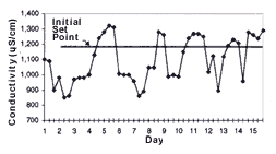
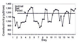
One of the most important steps in implementing a conductivity control system is defining the set point. The set point determines the amount of rinse water used and the upper limit of acceptable chemical concentrations in the rinse water. The higher the set point, the lower the overall rinse water use. To determine the set point, conductivity in the rinse tank should be monitored before system installation to determine its conductivity range (see Figure 3).
Initially, conductivity control system set points should be established at the high end of the rinse water conductivity range. Set points can be increased if process operations remain unaffected and further reductions in rinse water use are desired. Set points can be reduced if parts are not adequately rinsed or if dragin to subsequent process tanks adversely affects process operations. A record of set points, process bath conditions and parts rejected because of poor rinse quality should be maintained to help determine optimal set points.
Case study: Artistic Plating and Metal Finishing, Inc. The Merit Partnership sponsored a P2 project that involved installing and evaluating conductivity control systems at Artistic Plating and Metal Finishing, Inc, a medium-sized finishing facility in Anaheim, CA. The main objective of the P2 project was to evaluate the effectiveness and benefits of using conductivity control systems on various finishing processes.
Artistic performs copper, nickel and chrome plating on a hand-operated rack line and copper plating on a manually operated barrel hoist line. The facility specializes in plating zinc diecast parts for commercial customers and operates up to three shifts per day. Wastewater is sent to an onsite wastewater treatment system (WWTS). Treated wastewater is discharged to the local publicly owned treatment works, and sludge (filter cake) is disposed of offsite.
| Table I—Conductivity Control System Results | |||
| Per Month | Monthly Savings | ||
Rinse Water Use Wastewater Discharge WWTS Chemical Use WWTS Sludge |
Before 516,000 gal 516,000 gal $4,000 not qualified |
After 296,000 gal 296,000 gal $3,200 not qualified |
$280 $110 $800 |
Total Cost for Nine Systems = $14,500 Total Savings = $14,300/year Payback Period = 1.0 year |
|||
Case study system setup
The analyzers for the conductivity control systems on the rack line at Artistic were mounted on a common control panel. Cables from the analyzers to the sensors and solenoid valves were run below the floor grating and protected from moisture by conduit. The analyzers for the conductivity control systems on the barrel line were mounted on a nearby wall. Artistic monitored rinse water conductivity for 3 weeks before system installation to determine the operating conductivity range of each rinse tank. Based on this information, the initial set point on all analyzers was set at 1,200 microSiemens per centimeter (µS/cm), with a deadband of 50 µS/cm. During 3 months of operation, no negative production impacts occurred (inadequate rinsing or dragin to subsequent process tanks). Artistic may therefore eventually raise the set points.
Conductivity control system maintenance includes monthly calibration checks performed by comparing the conductivities measured by the conductivity control systems with those measured by a calibrated, hand-held conductivity meter. During 3 months of operation, the sensors did not need cleaning.
Case study costs
The costs for conductivity control systems ranged from $290-$1,140 per system. Other hardware, such as mounting equipment, conduit and wiring, cost an additional $100-$250 per system. Installation was performed by an outside contractor for $400-$600 per system. System operation and maintenance activities are currently performed by a contractor but may eventually be performed by Artistic.
Although the conventional conductivity control systems require less capital cost, Artistic believes the electrodeless systems are likely to be more cost-effective in the long term because they are easier to operate and maintain.
Case study results
After two weeks of adjustment, the conductivity control systems performed effectively. Analyzers with digital displays and programmable set points were easiest to use and allowed better control of rinse water flow than analyzers with no display and analog set points. During 3 months of conductivity control system operation, no adverse impacts on process quality were observed. The conductivity control systems have provided several benefits: decreased rinse water use; decreased wastewater generation; decreased WWTS chemical use; and decreased WWTS sludge generation (see Table I).
After 3 months of operation, the conductivity control systems have reduced rinse water use and resulting wastewater generation at Artistic by 43% (see Figure 4). According to the facility production manager, production was steady during this period. Artistic has saved a total of $390 per month on city water purchase and sewer discharge fees.
Conductivity control systems significantly reduce overall rinse water use and wastewater volume. Therefore, if dragout remains constant, the average concentration of metals in the wastewater will increase. Studies have shown that treating smaller volumes of more concentrated wastewater can reduce treatment chemical use and associated costs. This effect is realized because finishers use treatment chemicals in quantities that greatly exceed stoichiometric requirements. Reducing wastewater volume and treatment chemical use may also reduce the volume of sludge (filter cake) generated because a significant portion of sludge mass can be attributed to treatment chemicals (for example, lime) and their reactions with naturally occurring ions (for example, carbonates, phosphates and sulfates) present in water that are removed during treatment.
In addition, reduced wastewater generation will result in a lower flow rate through the WWTS, which can increase retention time in the treatment tanks and improve WWTS performance and efficiency, further reducing treatment chemical requirements. Because the evaluation period was not long enough to allow adequate sludge generation data to be gathered and because the facility changed the type of flocculant used in the WWTS, sludge reduction was not quantified.
Read Next
Episode 45: An Interview with Chandler Mancuso, MacDermid Envio Solutions
Chandler Mancuso, technical director with MacDermid Envio discusses updating your wastewater treatment system and implementing materials recycling solutions to increase efficiencies, control costs and reduce environmental impact.
Read MoreDelivering Increased Benefits to Greenhouse Films
Baystar's Borstar technology is helping customers deliver better, more reliable production methods to greenhouse agriculture.
Read MoreEducation Bringing Cleaning to Machining
Debuting new speakers and cleaning technology content during this half-day workshop co-located with IMTS 2024.
Read More










.jpg;maxWidth=300;quality=90)


