Rolling Ring Linear Motion in Finishing Machines
Rolling ring linear motion assemblies may be used in a wide range of finishing machines, performing applications such as painting, coating, positioning, cutting, spooling/winding, spraying, slitting and packaging...
Rolling ring linear motion assemblies may be used in a wide range of finishing machines, performing applications such as painting, coating, positioning, cutting, spooling/winding, spraying, slitting and packaging. Rolling ring linear motion benefits finishers in three ways:
- Elimination of complex, electronic controls reduces overall machine cost;
- Simplified operation and maintenance reduces investment in specialized skills and training;
- Less downtime for repairs and control adjustments results in longer periods of uninterrupted production time.
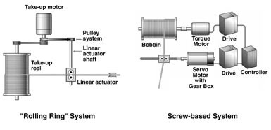
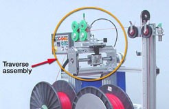
These types of machines incorporate a linear drive assembly to move the tool mounting head (drive head) back and forth (Fig. 1). A primary design goal is smooth, accurate linear motion, possibly with requirements for automatic reversal and the ability to change linear speed.
Traversing or reciprocating systems offering automatic reversal of the tool mounting head and the ability to adjust pitch (linear speed) almost invariably involve a variety of components, such as sensors, clutches, encoders and gear boxes. Depending on the linear motion requirements dictated by a specific finishing process, however, it is frequently possible to simplify system design, operation and maintenance by using mechanical methods for motion control demands.
Simple operating principle
Standard ball bearings typically serve to reduce friction in rotating assemblies, much like the bearings in the hub of a wheel. Rolling ring bearings, however, are designed to create linear output from rotary motion input.
A rolling ring bearing begins as a standard ball bearing. A special machining process creates a sort of "ridge" that runs around the center of the bearing's inner race surface. When mounted on a shaft, a rolling ring bearing contacts the shaft only on the apex of this ridge (Fig. 3).
There is clearance between the shaft and bearing on either side of the ridge. This clearance permits the bearing to be pivoted, angled left or right on the shaft and still maintain point contact with the shaft.
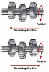
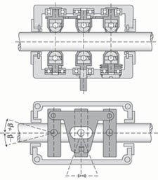
A three or four rolling ring bearing assembly is fixed within the housing. Each bearing is held at a specific angle relative to the shaft (Fig. 4). When the shaft rotates, the rolling ring bearings generate axial force on the central ridge. This causes the bearing assembly to roll along the length of the shaft. The rotary input provided by the motor-driven shaft is thereby converted to linear output. As the bearing assembly moves, it carries the tool mounting head with it.
A simple spray painting process, for example, probably does not need a complex electronic control system to move the spray head back and forth. Rolling ring linear drive assemblies are commonly used in these situations, because in most instances rolling ring engineering eliminates the need for these controls as well as the need for clutches, cams, gear and variable speed reversible motors (Fig. 2).
Instant reversal without special controls
The angle at which the rolling ring bearing assembly contacts the shaft is adjustable. The travel direction of the tool mounting head is determined by this angle. Changing the angle of the bearing assembly is done mechanically making the reversal process totally independent of the drive motor or other controls.
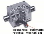
Reversal occurs when contacting a hardware fixture called an "end stop" triggers the spring-actuated reversal mechanism (Fig. 5). When the reversal mechanism is triggered, the entire rolling ring bearing assembly is flipped on the shaft to its opposite to mirror position and reversal is instantaneous (Fig. 6). The end stops are user-positioned to determine the system's stroke length.
At no time does the rolling ring bearing lose contact with the drive shaft. This is how rolling ring linear drive assemblies prevent backlash, because there is no play between shaft and bearing. Furthermore, the shaft on which a rolling ring bearing operates is not threaded, which means dirt and debris cannot be trapped and cause clogging or jamming. Mechanical control over linear speed.
Manipulating the angle of the rolling ring bearing assembly on the shaft also controls the pitch or distance traveled per shaft revolution. This is useful when a process calls for a gradual decrease/increase in speed before or after reversal. This "ramping" down or up is usually used to lessen the effects of jarring or jerking on the payload attached to the linear drive.
For example, suppose a finishing operation involved the attachment of a buffer on the end of an extension arm. The extension arm, mounted to the tool mounting head, travels back and forth when the system is in operation. If reversal is not gentle, the inertia and whip-like action of the arm could wrench or torque the system, possibly damaging system components. Meeting application requirements for ramping up or down during the reversal process can mean designing in clutches, gearboxes and control systems. With a rolling ring system, however, controlled changes to linear speed are achieved with relatively inexpensive mechanical modifications to the auto-reverse mechanism.
The linear speed of the tool mounting stage may be changed while the drive is operating simply by adjusting the pitch control (Fig. 7). Adjusting the pitch control changes the angle of the rolling ring bearing assembly on the drive shaft. This increases or decreases the drive head's travel distance relative to each revolution of the shaft. This translates into an increase or decrease of linear speed, even if the drive motor speed and rotational direction remain unchanged. Thus, a variable speed system may be driven by a relatively inexpensive, single-speed, uni-directional motor.
The reversal mechanism may also be configured so that it rotates the rolling ring assembly to be perfectly perpendicular to the shaft. This causes the drive head to dwell. The pitch is zero and there is no linear movement, even though the shaft-ring contact is still intact (Fig. 8). When the ring assembly is again angled on the shaft, usually accomplished with an air cylinder or other actuating device, linear motion resumes.
A rolling ring linear drive assembly is typically supplied within a production framework (Fig. 9). The end stops are preconfigured to provide the desired linear motion.
Technical considerations
In some cases, rolling ring drive systems do require additional controls to meet application requirements. An example is a spot grinding operation where the tool head must be accurately positioned forward and backward on the shaft.
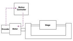
This requires two-way shaft rotation and the rolling ring system might employ a PLC controller as illustrated in Fig. 10. Generally, a rolling ring system readily lends itself to various types of mechanical manipulation that exploit the unique performance of the rolling ring bearing to permit control over the reversal and pitch of the traversing housing.
Accuracy with rolling ring systems is typically to within + 0.005 inch, at speeds up to 13 fps over distances of 16 ft maximum. Some rolling ring linear motion systems offer increased accuracy to within +0.0004 inch. Rolling ring systems generally are not used if incremental linear movement in the <0.0004 inch range is required.
Rolling ring assemblies are designed to perform finishing processes requiring reciprocating and positioning linear motion. For processes involving repetitive, reciprocating motion such as slitting or spraying, rolling ring assemblies pose a practical alternative to avoiding the operating and maintenance costs associated with traditionally developed linear motion systems.
Low operating/maintenance costs & less downtime
Since, reversal of direction and changes to linear speed and travel direction are possible without slowing or stopping the drive motor, production machinery may be operated for longer periods without spotting for adjustments. Freedom from a complex and costly control system results in reduced set-up costs, low operator training costs and lower maintenance expenditures. With simpler controls there are fewer electrical and mechanical problems, and production machinery downtime is reduced. Periodic lubrication of the drive shaft is the only maintenance required.
Built-in overload protection
Because there are no threads on the rolling ring drive shaft, a rolling ring system requires no bellows assembly to protect the shaft from debris and dirt. The shaft remains clog-free even in dirty working environments. No shaft cleaning means less downtime and better production rates. Additionally, the smooth shaft will "slip," not jam, in the event of overload, whereas a threaded shaft may continue to "churn," causing damage to expensive system components.
Tool head accepts load directly
There is no need to purchase linear bearings, slide mechanisms or other load carrying devices. The tool may be attached directly to the rolling ring tool head stage or "nut."
Free movement on shaft
Rolling ring systems generally feature a free movement lever. This permits manual or pneumatically actuated positioning of the tool head while the system is stopped. Screw-based systems require the shaft to turn in order to move the nut. The free movement lever eliminates the need to start-and-stop, or "jog" the system to position the tool head. This saves time and expedites production.
Backlash free
The design of a rolling ring bearing assures continuous point contact with the drive shaft that eliminates backlash. To prevent backlash, other devices can require the purchase of expensive preloaded nuts or other device to load the gear train. Rolling ring linear motion machines can make finishing operations simpler by reducing the need for a number of complex controls, specialized training and an uninterrupted project line due to repairs and control adjustment.
To learn more visit Amacoil, Inc..
Related Content
Robots, AI and Superb BMW Surfaces
There isn’t an automotive paint shop in the world that doesn’t have post-paint inspection and defect processing. But BMW is doing this with levels of technology at a plant in Germany that exceed all other paint shops in the world.
Read MoreShedding Light on Surface Inspection
State-of-the-art reflector-based lighting system improves luminosity and ergonomics for surface inspection tasks while reducing energy usage.
Read MoreMasking Solutions Provider CFS Dramatically Expands Capabilities and Capacity
Custom Fabrication & Supplies (CFS) completed a new plant expansion packing 10 times the capacity into twice the space. It dramatically enhances the supplier’s custom capabilities to provide extremely precise and cost-effective masking solutions.
Read MoreCuring Oven Basics
Simply heating up the substrate does not cure the coating. There are many variables to consider when choosing the best cure oven for your application...
Read MoreRead Next
A ‘Clean’ Agenda Offers Unique Presentations in Chicago
The 2024 Parts Cleaning Conference, co-located with the International Manufacturing Technology Show, includes presentations by several speakers who are new to the conference and topics that have not been covered in past editions of this event.
Read MoreDelivering Increased Benefits to Greenhouse Films
Baystar's Borstar technology is helping customers deliver better, more reliable production methods to greenhouse agriculture.
Read MoreEducation Bringing Cleaning to Machining
Debuting new speakers and cleaning technology content during this half-day workshop co-located with IMTS 2024.
Read More


