Slowing the Pulse
How a new approach to pulse anodizing can decrease energy consumption and improve productivity
Most anodizing job shops use DC or pulse anodizing with pulses in milliseconds. Processing time for forming a 20-μm thick anodic oxide layer with these methods is normally in the area of 60 min.
Our research has shown that using slow, square-formed pulses can decrease processing time by up to 50% and total energy consumption in the anodizing tank by up to 30%. With a few equipment modifications, existing anodizing lines can be retrofitted to take advantage of the process.
Why Pulse?
The whole idea of using pulse anodizing is to reduce processing time by subjecting parts to a higher average current density during anodizing. Pulsing between two values of direct current instead of using the same value during the whole process provides several possibilities to optimize processing conditions.
When the higher voltage in a pulsed process is applied, current will eventually reach a steady level. During this time the anodic film will reach a thickness proportional to the applied voltage. Its microstructure will also be controlled by voltage.
When voltage is rapidly lowered, current density decreases to a very small value. This small current density—in the range of microamps—corresponds to very high resistance in the anodic film. The electrical field across the barrier layer in this period is very low; thus the rate of anodic film formation slows to almost zero. Field-assisted dissolution is also very low; the main reaction in this period is chemical dissolution. This period is called the recovery period.
After a period of time, the length of which depends on factors such as the specific alloy being processed, electrolyte concentration and temperature and voltage change, the anodic layer will thin enough to allow an increase in the electrical field across the layer. Now field-assisted dissolution and formation will take place, increasing the total dissolution rate due to lower resistance in the reduced thickness of the oxide layer.
After a while, current density will reach a steady level corresponding to the value of the lower voltage. At this point the anodic layer reaches a new thickness that corresponds to the lower voltage. The layer will also adopt have smaller cells corresponding to the lower voltage.
Slowing the Pulse
Until now, there has been no convincing evidence to prove that pulse anodizing with slow pulses is much more effective than using fast pulses. As a result, the anodizing industry has rejected slow pulsing because too many have invested in new rectifiers without obtaining the expected energy savings.
Instead, additives and increasing acid concentration and temperature have been suggested as ways to save energy. But our research has shown that the electrolyte should be as simple as possible to maximize quality and energy savings. The electrolyte we recommend contains not more than 200 g/L (18 wt%) sulfuric acid with aluminum content of 5–15 g/L. Temperature should not exceed 20°C (68°F), and current density should be 1.5–2.0 A/dm2 (~15–20 asf).
Much research has been done on the subject of using square-wave pulses. The whole idea of using pulse anodizing is to have a higher average current density and hereby reducing the process time. But to use pulses as a means to reduce energy consumption, the anodizing system must have a busbar able to drive sufficient current and agitation in the tank sufficient to provide adequate cooling during periods of high current density.
This article will describe our research to optimize pulse frequency and current density and how this technology can be retrofitted to an existing anodizing line.
Pulse Optimization
Pulsating between two values of current density works because it gives the aluminum surface time to recover during low-current-density periods. The length of these periods should be in the range of 10–240 sec because two different dissolution mechanisms are taking place during anodizing.
These two mechanisms take place with very different rates. Field-assisted dissolution occurs at up to 300 nm/min of oxide formation. Chemical dissolution is much slower, with rates up to 0.1 nm/min of oxide formation.
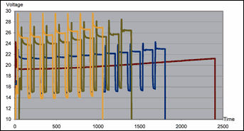
Constant current during the anodizing process will result in an increase in voltage due to the growing aluminum oxide layer. This increase in voltage is directly proportional to current density.
We undertook research to find optimal pulse times and current densities for process energy savings by using four current density parameters to produce an anodic film 20 μm thick on parts fabricated from aluminum alloy 6063. The components, profiles with a medium complicated geometry, were subjected to conventional pretreatment before anodizing.
Parts were anodized using DC anodizing with no pulse and pulse anodizing at three different three current density levels. In each case, pulse time was 120 sec for the high current and 30 sec for the low current. Maximum voltage never exceeded 30 V at any time, and the observed voltage increase was not linear.
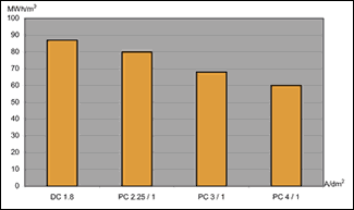
We then calculated energy consumption for each process in megawatt hours per cubic meter (MWhr/m3) to provide a measure of the amount of energy used per micron of formed oxide layer. The square-wave formed pulses reduced process time so much that the increase in voltage had no negative influence on total energy consumption. We logged voltage drops over various areas of the parts every second during anodizing and calculated energy consumption from the logged voltage drops and the current running trough the system.
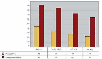
The DC process used 87 MWhr/m3. All the pulsed processes had lower energy consumption, with the process pulsating from 4 to 1 A/dm2 requiring 60 MWhr/m3—a decrease of 31% in energy consumption.
Processing time was similarly reduced. The DC process required 40 min to produce the anodic film; pulse anodizing with current density varying from 4 to 1 A/dm2 required only 18 min to produce a film with the same thickness, a decrease of more than 50%.
Quality of the oxide layer was the same for all four processes. All films withstood 1000 hr of neutral salt spray testing per ASTM B 117.
Retrofitting an Existing Line
In order to implement pulse anodizing, most shops will have to take into account a few very important equipment and process management considerations.
First, the shop must acquire a considerable amount of theoretical knowledge about the principles of pulse anodizing. This is important not merely to gain a basic understanding of the process, but is also needed to maximize the expected advantages of pulse anodizing in daily production.
Second, something that almost always needs to be changed when implementing pulse anodizing is the rectifier. Rectifiers used for this process should allow a range of current densities from 2–20 A/dm2. The rectifier must be coupled to a monitor capable of displaying real-time current/voltage curves as the process progress. It may also be necessary to replace the busbars with larger ones and refresh the contact points between the busbar and flight bar.
The increase in throughput made possible by switching from DC to pulse anodizing also must be taken into account in pre- and post-anodizing processes. Pretreatment, racking and sealing processes should not be allowed to become bottlenecks. Racking can be done automatically to keep up with the increased throughput of the anodizing line, It may also be necessary to install extra pretreatment and sealing tanks.
Once the necessary investments in knowledge and equipment are made, the task of managing the process begins. One key to efficient pulse anodizing, for example, is finding the recovery period required by parts fabricated from different alloys and with different geometries. This can be done by running voltage control tests.
Pulse anodizing also requires vigorous agitation, which must be maintained throughout the process. The primary purpose of agitation is to maintain temperature in the electrolyte and in the growing oxide layer.
Air is often used for cooling, but this has disadvantages including a high fume level and reduced solution conductivity due to the non-conducting nature of the air bubbles. Using the electrolyte for agitation through flow eductors will provide better temperature uniformity, and it is possible to direct the eductor flow at the work.
Related Content
Practical Environmental Management Reduces Costs, Refines Quality
By focusing on effluent treatment and efficient tin recovery, this Indian surface treatment plant meets stringent environmental standards and sustainable high-quality production.
Read MoreCordless Sprayer Offers 3 Configurations
Titan’s Impact X 120 18V sprayer delivers up to 4 gallons per charge, reducing overspray by 50% and using a single battery system for multiple tools.
Read MorePPG Paints, Coatings for Battery EVs Showcased at Germany Battery Show
PPG is attending The Battery Show in Stuttgart, Germany.
Read MoreSolar-Powered Photonic Cooling Enables Energy-Saving Coating
Passive cooling technology can reduce interior temperatures 5-13°C, offering weight, cost and CO2 benefits for cars, construction, aircraft and more.
Read MoreRead Next
Episode 45: An Interview with Chandler Mancuso, MacDermid Envio Solutions
Chandler Mancuso, technical director with MacDermid Envio discusses updating your wastewater treatment system and implementing materials recycling solutions to increase efficiencies, control costs and reduce environmental impact.
Read MoreDelivering Increased Benefits to Greenhouse Films
Baystar's Borstar technology is helping customers deliver better, more reliable production methods to greenhouse agriculture.
Read MoreEducation Bringing Cleaning to Machining
Debuting new speakers and cleaning technology content during this half-day workshop co-located with IMTS 2024.
Read More


.jpg;maxWidth=300;quality=90)


