The Basics of Vibratory Bowl Set-up
Having worked in the metal finishing field for more than 25 years I have experienced a number of efficiency problems with customer’s vibratory bowls that typically relate back to a universal conundrum—they aren't set-up correctly....
Incorrect set-up is such a common occurrence that it’s helpful to periodically review the basics related to vibe bowl set-up and motion efficiency. A better understanding of these basics will help the vibe room operator maximize product throughput, minimize cycle cost/time and simultaneously improve part quality.
Vibratory Bowl Basics and Mass Motion
The vibratory bowl consists of an I.D., inner circle hub that houses the motor and drive shaft assembly and an O.D. circular wall forming a torroidal, bagel-shaped operating channel (see Figure 1). Vibratory media—ceramic, metal, or plastic—is added to the channel plus the parts to be vibe finished. By adjusting the bowl’s drive shaft weights and likewise the alignment angle between the weights the vibe operator can affect the bowl’s parts/media mass rotational pattern and rolling speed.
To generate motion within the bowl, the bowl itself must be capable of movement. A quick inspection will reveal that the bowl physically sets upon a series of springs mounted to the upper circumference of a stationary base. The base is simply the spring platform and it is typically fixtured firmly to the shop floor.
Observation of a vibe bowl in operation reveals two planes of motion. The media/parts mass will rise at the O.D. wall and fall downward at the center hub. This motion is referred to as roll. Simultaneously, the mass will travel in a clockwise or counter-clockwise lapping path around the channel; direction is determined by motor rotation (envision race cars lapping a race track.) This type of motion is referred to as slide (see Figure 2).
By combining these two motions, roll and slide, the parts will actually traverse the channel in a helix pattern. A tight helix yields more rolls per lap and a longer path that the parts must travel while making a single lap around the channel. This type of pattern generates greater media contact per lap and thereby shortens processing time (see Figure 3).
Inversely, an open helix yields less rolls per lap and a shorter distance traversed per lap. A shorter distance traveled per lap reduces overall media contact and thereby increases cycle time.
Since the center hub is a smaller diameter circle than the O.D. wall, the parts consequently get closer together as they fall into the center hub. A tight helix pattern will increase the closeness of the parts at the hub and the resultant part-on-part contact. Such a roll pattern would be suitable only for parts of the physical characteristics that could sustain such contact. Heat-treated, hardened steel work pieces would be an example.
Likewise an open helix would reduce the potential for part-on-part contact and would be better suited for parts of a more delicate metallurgical nature. Parts such as aluminum machinings, brass stampings and zinc die castings would be better suited for processing in an open helix pattern. (Observing a golf ball in the channel is an excellent way to monitor the helix pattern.)
Adjusting Vibe Bowl Eccentric Weight Segments
A cut-away view through a vibe bowl will reveal a vertically mounted drive shaft. This shaft is rotated by the bowl’s motor either directly or by a series of v-belts. Mounted to both the top and bottom of the drive shaft are eccentric plates. Adding or subtracting weight segments to the bottom plate, the vibe operator will change the bowl’s amplitude. Amplitude is a measure of the compression and expansion of the bowl’s springs (see Figure 4).
Adding weight segments to the bottom plate will increase the vibratory amplitude due to the increased imbalance between the top and bottom weights on the drive shaft. As such, the motion in the machine will be more aggressive—an operating characteristic necessary to lift and roll heavy parts. However, aggressive roll will increase the propensity to generate part-on-part contact damage thereby limiting its application to parts suitable of accepting this type of action.
Inversely, removing weight segments from the bottom eccentric plate brings the drive shaft closer to being in balance and consequently decreases the vibratory amplitude. This is visually seen as a less aggressive rolling action—a more suitable action for metallurgically delicate parts.
Adjusting Weight Alignment Angles
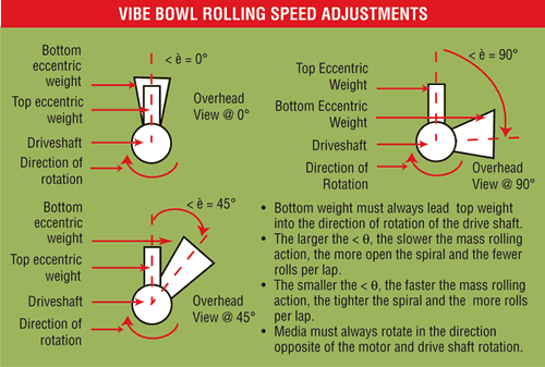
If it were possible to stand directly over the drive shaft and look down onto the vibe bowl, it would be possible to view the angular difference between the top and bottom eccentric plates. By making the angle more acute (i.e. smaller) or by making the angle obtuse, (i.e. larger) the vibe operator will change the rolling speed of the mass within the bowl channel (see Figure 5).
A vibe bowl is typically set-up at a 90-degree angle with, and this is a must, the bottom weight leading the top weight into the direction of drive shaft rotation. Nearly all vibe finishing applications will be run at this angle. It is very rare to require a more acute or more obtuse angle; however, if required, it will affect the resulting rolling speed of the mass.
Making the angle more acute will tend to concentrate all the eccentric weights, both top and bottom, onto one side of the drive shaft. This increased imbalance results in an aggressive shaft rotation and consequently a more rapid rolling speed of the mass in the channel.
Making the angle more obtuse will tend to disperse the eccentric weights, both top and bottom, to opposite sides of the drive shaft. By uniformly dispersing the weights, the operator is essentially attempting to balance the drive shaft and will thereby force a smoother more uniform drive shaft rotation. As a consequence, the rolling speed of the mass will be decreased.
Angle alignment can be used in a secondary technique to fine-tune the helix pattern. Consider for example an alignment angle that was opened up from 90 degrees to 110 degrees. This opening would slow the roll rate of the mass. Since the parts in the channel will take a longer time to rise and fall, they will be carried further in the sliding action thereby generating a more open helix.
The Four Principle Rules of Vibratory Bowl Set-up
Placing new bowls into operation or returning bowls to operation after maintenance is a critical time for correctly calibrating the vibratory motion. Have you ever noticed that the mass is hopping in the channel? Or perhaps, the mass rises in the middle of the channel and splits to both the O.D. wall and the center hub? These are indications the bowl set-up is not correct and here is a troubleshooting primer to correct these problems.
Rule Number 1: Inspect the bowl’s motor. Look for the directional rotation sticker or plate and be certain that the motor is rotating in the correct direction. If the rotation is reversed, simply have the shop electrician reverse the electrical leads to return the rotational direction to the correct direction.
Rule Number 2: Assuming rule number 1 was followed and the motor is rotating in the correct direction, the mass in the channel should move in the opposite direction. Since the mass is heavy and by rights would ordinarily remain stationary, the forward movement of the motor’s rotation causes an equal and opposite reaction in the mass. If the mass is moving in the same direction as the motor check for the following:
- Review Rule No. 1—chances are the motor is still rotating in the wrong direction.
- Review Rule No. 3—the bottom weight may be trailing the top weight into the direction of rotation of the drive
shaft.
Rule Number 3: Assuming rule number 1 and 2 are correct, the bottom weight must lead the top weight into the rotation direction of the drive shaft. Let us assume that the drive shaft is rotating in a clockwise direction as viewed from over head. Position the top weight so that it aligns to the 12 o’clock position. The bottom weight should be at 3 o’clock for a 90-degree alignment angle. If the bottom weight trails into the rotational direction, then the mass may be seen as doing any one of the following peculiar actions:
- Rolling backwards; rising at the center hub wall and rolling to the outside.
- Splitting in the middle of the channel and rolling half into the center hub and half out to the O.D. wall.
- Rolling in the same direction as the drive shaft rotation.
Rule Number 4: Assuming rule 1, 2 and 3 have been followed accurately, set the alignment angle at 90 degrees to begin. Then, close the angle down to increase rolling speed or open angle up to decrease rolling speed.
Conclusion
Vibe bowls can be adjusted to produce both gentle and aggressive action by the placement of weight segments on the drive shaft and by adjusting the alignment angle of the weights in relationship to one another. Using the four principle rules of vibe bowl set-up is an excellent way to check on the operating characteristics of any vibe regardless of when it was installed or when its motion was checked last.
The motion of the mass in the vibe bowl channel is actually a helix. A tight helix has more rolls per lap and a further distance traveled per lap thereby increasing media/part contact and shortening the processing time. Since the tight helix increases part-on-part contact, especially when parts fall at the center hub it should be limited to harder more durable parts such as heat-treated, hardened steel. An open helix has fewer rolls per lap and a shorter distance per lap and is better suited for metallurgically delicate metals such as brass, aluminum and zinc die castings.
Related Content
Top Reasons to Switch to a Better Cleaning Fluid
Venesia Hurtubise from MicroCare says switching to the new modern cleaning fluids will have a positive impact on your cleaning process.
Read MoreAlkaline Cleaning Guide
Gregg Sanko, Senior Chemist, Oakite Products, Inc. provides an overview of the alkaline cleaning process.
Read MorePrevent Plating Problems with Critical Inspections
Tanks and their contents should be regularly inspected visually and analytically. When a quality issue arises, it is important to quickly pinpoint where the main problem is by checking which parameter is out of line.
Read MoreUnderstanding and Managing White Spots on Anodized Aluminum
Having trouble with spotting defects when anodizing? Taj Patel of Techevon LLC offers a helpful overview of the various causes of white spots and potential solutions.
Read MoreRead Next
A ‘Clean’ Agenda Offers Unique Presentations in Chicago
The 2024 Parts Cleaning Conference, co-located with the International Manufacturing Technology Show, includes presentations by several speakers who are new to the conference and topics that have not been covered in past editions of this event.
Read MoreDelivering Increased Benefits to Greenhouse Films
Baystar's Borstar technology is helping customers deliver better, more reliable production methods to greenhouse agriculture.
Read MoreEpisode 45: An Interview with Chandler Mancuso, MacDermid Envio Solutions
Chandler Mancuso, technical director with MacDermid Envio discusses updating your wastewater treatment system and implementing materials recycling solutions to increase efficiencies, control costs and reduce environmental impact.
Read More


.jpg;maxWidth=300;quality=90)


