Correlation Between Electrochemical Behavior and Neutral Salt Fog Corrosion on TCP Coated AA2024
Differences in open circuit potential, electrochemical impedance spectroscopy and Tafel analysis were observed and quantified between the best- and worst-performing processes.
Editor’s Note: The following is a paper based on a presentation given at NASF SUR/FIN 2019, in Rosemont, Illinois on June 3, 2019 in Session 2, Advances I: Surface Finishing Technology Today. A pdf of this paper can be accessed and printed HERE; the complete Powerpoint presentation is available by clicking HERE.
ABSTRACT: A correlation was found between electrochemical properties and the corrosion of a trivalent chromium pretreatment (TCP) coated aluminum alloy (AA2024-T3) during neutral salt fog exposure. Differences in open circuit potential, electrochemical impedance spectroscopy, and Tafel analysis were observed and quantified between the best-performing processes (longest time in salt fog/lowest pit count) and the worst-performing processes (shortest time in salt fog/highest pit count). The best-performing processes exhibited a less negative open circuit potential, lower coating capacitance, less negative corrosion potential, less negative pitting potential and smaller corrosion currents, compared to processes that failed quickly in salt fog. Overall, a link was shown between electrochemical behavior and neutral salt fog corrosion resistance to help predict which processes will provide the most corrosion resistant TCP coatings in a significantly shorter time than a full neutral salt fog test.
1. Introduction and background
Extensive salt fog testing is required (up to 1,000 hr) to predict how well a coating will protect a basis metal in real-world applications. Electrochemical testing generally takes only a few hours and could predict how well a coating will perform in salt fog. A robust correlation between electrochemical testing and salt fog performance was found and quantified for a trivalent chromium pretreatment coating on aluminum alloy 2024-T3.
The neutral salt fog corrosion test, ASTM B117, is the current standard to determine corrosion performance of a surface coating system. However, it had many drawbacks. Although it can serve as a good process control check, there is poor correlation with actual field performance. Further, testing to failure requires up to 1,000 hours (more than one month). In the end, it is difficult to compare processes thoroughly and quantitatively.
Electrochemical analysis offers a new method to test performance. It has been found to provide good correlation with field performance on other metals,1,2 as well as correlate with salt fog results when flaws are introduced to coatings on aluminum.3 The method is fast, reducing test time from weeks to hours or days. One can easily and comprehensively compare and rank processes, different coatings and different base metals. To date however, it has been mainly tested/linked with field tests on primed/painted panels with or without scribes.
The purpose of this work is to link electrochemical analysis to neutral salt fog testing for coated but undamaged metals. This allows one to optimize new pretreatment processes more quickly and efficiently with electrochemical analysis, pursue future uses in new product development and in new pretreatment process development, and save time and money on extensive salt fog testing or developing new products/processes that do not perform well in field testing.
2. Aluminum alloy 2024-T3
The focus of this work is on aluminum alloy 2024-T3. Its composition is given in Table 1.
Table 1 - Composition of aluminum alloy 2024-T3.

The 2000 series alloys pose a number of problems in surface finishing. A high copper content is alloyed with the base aluminum, and there is a tendency to form large copper-rich sites on the surface which tend to coat unevenly. A galvanic cell is formed between copper and aluminum, promoting aluminum degradation. Compared to other aluminum alloys, high levels of corrosion are experienced. In processing, it is more difficult to coat uniformly and homogeneously. To produce the best, most corrosion-resistant conversion coatings, this alloy requires more careful surface preparation and coating formation than any other aluminum alloy.
The corrosion of aluminum on vehicles tends to be cosmetic rather than catastrophic, as steel corrosion was in the past. Early implementation of aluminum hoods on Fords led to galvanic corrosion/paint delamination due to their direct connection with steel brackets.4
More catastrophic failures, however, have been seen with aerospace applications of aluminum. A 1999 incident was related to fuselage skin panels disbonding and fatigue cracking at lap joints.5 A 2005 crash involved the loss of a wing from corrosion, causing fatigue cracks on the wing/fuselage junction brackets.6
3. Preventing corrosion on aluminum alloys
Aluminum alloys have an overall matrix composed of aluminum, which is alloyed with various other metals. One universal benefit of aluminum or its alloys is a naturally forming aluminum oxide layer, shown in Fig. 1, which occurs when the alloy is exposed to any oxygen in the environment. Some metals will be distributed throughout the aluminum matrix more evenly, such as Zn and Cr, while others will aggregate into clusters together, called intermetallic particles (IMPs).
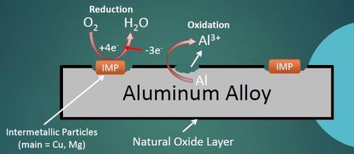
Figure 1 - Corrosion mechanism in 2024 aluminum alloy.
AA 2024 particularly useful for structural components on aircraft (wing and fuselage structures), due to the high strength of the alloy coupled with good fatigue resistance. When 2024 is exposed to a corroding environment, such as saltwater or acidic clouds, the IMPs act as active sites which use electrons to assist with the oxygen reduction reaction. These electrons catalyze the aluminum oxidation by pulling free electrons away from the adjacent aluminum matrix. This leads to aluminum oxidation to free aluminum ions which leave the bulk metal causing pits.
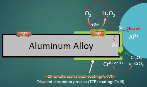
Figure 2 - Corrosion mechanism with a chromium conversion coating applied to 2024 aluminum alloy.
When a conversion coating is applied to the aluminum alloy surface, it completely covers both the aluminum matrix and any surface IMPs, providing barrier protection against the penetration of solution, hopefully to prevent any corrosion and any oxygen reduction at the IMP sites (Fig. 2). It should also prevent any aluminum oxidation, but the coatings do tend to have small pinholes and occasional cracks, so at the very least aluminum oxidation will be slowed. At any open sites where the aluminum is exposed, the hexavalent chromium in the coating will react with any oxygen present to form trivalent chromium oxides at the damaged sites to prevent further matrix loss. Trivalent conversion coatings do not exhibit this “self-healing” behavior like hexavalent conversion coatings. However, hexavalent conversion coatings are being phased out due to their health and environmental hazards.
All of this is relatively well known, especially for the chromium conversion coatings using hexavalent (Cr(VI)) chemistry. However, the well-known European Union (EU) Directives regarding Cr(VI) processes, including the Registration, Evaluation, Authorization and restriction of Chemicals (REACh), End of Life Vehicle (ELV), Restriction of Hazardous Substances (RoHS) and Waste Electrical & Electronic Equipment (WEEE) regulations have all but banned hexavalent chemistries from the European Union and, in effect, globally, as other nations and jurisdictions follow the lead of the EU.
A viable alternative involves trivalent Cr(III) conversion coating processes. The question therefore becomes, do the Cr(III) coatings provide the same full barrier coverage despite the lack of active corrosion prevention?
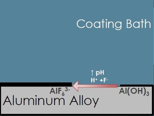
As shown in Fig. 3(a), when the AA is exposed to the acidic coating bath, any residual oxide layer and some of the matrix itself is etched away with the fluoride and hydrogen ions, forming an aluminum hexafluoride interfacial layer, water, and hydrogen gas. The resulting decrease in hydrogen ions causes an increased pH at the metal surface, catalyzing the next steps of the coating formation process.
(a)
(b)
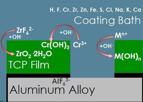
Figure 3 - TCP film composition and corrosion protection.
After the initial aluminum hexafluoride interfacial layer forms, the TCP coating itself begins to form (Fig. 3(b)), catalyzed by the increased surface pH. The free hydroxide ions present at the surface react with chromium present in the coating bath to form Cr(III) oxides, zirconium and fluoride complexes to form zirconium oxides, and some zinc to form zinc oxides. All of these oxides form a conformal coating which is hopefully free of hole and cracks to prevent any penetration to the aluminum surface below. These reactions can also be monitored using OCP measurement during the coating formation.
4. Salt fog and electrochemical measurement
4.1 Salt fog testing
Salt fog testing protocol is generally followed according to the following commercial and military specifications: ASTM B-117, MIL-DTL-5541 and MIL-DTL-81706. In general, the salt fog arises from a 5 ± 1 wt% solution of NaCl at pH 6.85 ± 0.35. A temperature of 35 ± 2°C is maintained inside the chamber, dispersing fog at 1.5 ± 0.5 mL/hr. Chamber performance is checked daily (minus weekends/holidays) with chamber open for < 1 hr. Test panels are set up in chamber tilted at 6° from vertical, with no salt spray directly impinging on the panels. Testing to failure (i.e., one panel with >5 pits or >15 pits over five panels exposed), the exposure time in the salt fog and the number of pits is recorded.
4.2 Electrochemical analysis
The setup for electrochemical analysis is shown in Fig. 4. Three electrodes are used in this test. The working electrode is the actual test sample, in this case a 2024-T3 aluminum alloy coated with a TCP-HF conversion coating. A saturated calomel electrode (SCE) is used as a reference, while a carbon rod is used as a counter electrode. The electrolyte in the cell is either a 1.0M NaCl solution or a 10 vol% Harrison’s solution (3.5 wt% ammonium sulfate plus 0.5 wt% NaCl in water). The test is run inside a Faraday cage to prevent electrical noise interference. Measurements use a Gamry*** potentiostat and curve fitting software.
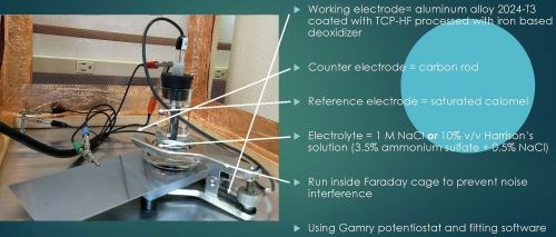
Figure 4 - Setup for electrochemical analysis.
There are three electrochemical methods employed in this work, each providing a unique measurement to be used for corrosion evaluation. They are:
- Open circuit potential (OCP) measurements
- Electrochemical impedance spectroscopy (EIS)
- Tafel measurements
4.2.1. Open circuit potential
Referring to Fig. 4, the voltage is measured between the reference electrode and the working electrode (coated aluminum panel) due to formation of a double layer at the working electrode surface, as per the Gouy-Chapman-Stern model, which describes the ionic environment in the region around a charged surface (Fig. 5).7 The potential arises through the rearrangement of water molecules and salt ions at the coated metal surface, because of the naturally occurring charge. The measurement is performed over an extended period of time to allow the system to reach equilibrium. A less negative potential indicates better corrosion resistance and a lower initial charge on the coated metal surface. Any associated current flow between the counter and working electrodes is due to electron and ion movement and is not recorded.
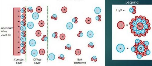
Figure 5 - Aqueous electrolyte-electrode interface: the Gouy-Chapman-Stern model for a NaCl solution.
4.2.2. Electrochemical Impedance Spectroscopy
Electrochemical impedance spectroscopy is particularly sensitive to surface changes at a level that is not detectable by other methods. Such changes include penetration of corrosion protective layers, including conversion coatings. The method goes beyond simple electrical resistance and measures the more complex property of impedance found in electrolytic processes. Here, resistance, capacitance and, to a lesser extent, inductance are studied.
Referring again to Fig. 4, the potentiostat applies a set potential between reference and working electrode, and current flows as a result of the applied charge on the coated metal working electrode. This set potential is fluctuated a small amount (~1 mV) in a sinusoidal pattern around the set potential while changing the frequency. The current is measured between the counter and working electrodes. The current data is fit to a representative circuit descriptive of the electrode/electrolyte interface, as shown in Fig. 6.
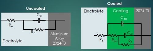
Figure 6 - Equivalent circuit elements in a electrode/electrolyte corrosion system.
In the uncoated aluminum alloy illustrated in Fig. 6, there is the circuit element RE, representing the electrolyte resistance, or resistance to electron flow through the salt solution. At the electrolyte/electrode interface (See Fig. 5), two equivalent circuit elements are in parallel: (1) CDL, the double layer capacitance, i.e., the charge held in the double layer interface, and (2) RP, the polarization resistance, i.e., the resistance to electron flow through the double layer.
The addition of the conversion coating presents a more complex equivalent circuit. As noted earlier, although a newly-applied conversion coating may be impervious to corrosion attack, it is not perfect and eventually pores do develop, and salt solution can penetrate through to the metal surface. The equivalent circuit is then further characterized by CCO, the coating capacitance, i.e., the charge held in the coating, and RPO, the pore resistance, i.e., the resistance to electron flow through the coating pores in series.
More comprehensive information on the principles of EIS is available elsewhere,8-11 but for the purpose of this paper, the known elements, such as the solution resistance, and the current / frequency response impedance data (in Ohms) are used to fit a Nyquist plot to determine values of the pore resistance and double layer capacitance.11 Nyquist plots involve complex numbers, with real and imaginary components. In the typical logarithmic plot shown in Fig. 7, the y-axis values represent capacitance. The measured diameter corresponds to the polarization resistance, which indicates the corrosion resistance. The higher the polarization resistance, (i.e., the larger the Nyquist plot diameter) the less corrosion occurring. The corrosion resistance of test samples can thus be evaluated and ranked.
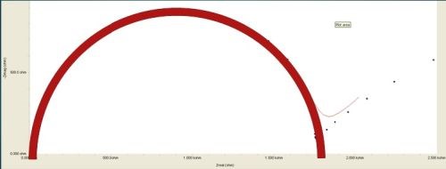
Figure 7 - Typical Nyquist plot: The measured diameter is the polarization resistance.
4.2.3. Tafel measurements
In Tafel measurements, or Linear Sweep Voltammetry (LSV), the applied potential is slowly ramped, going from a point more negative than the open circuit potential to a point more positive than the OCP to induce corrosion. At more negative potentials, oxygen reduction occurs; at more positive potentials, aluminum oxidation occurs.
Here, the potentiostat applies a set potential between reference and working electrode, and current flows as a result of the changing charge on the coated metal working electrode (measured between the counter and working electrodes). Differences in the current flow indicate the performance of the coated metal working electrode, and a lower measured current means less corrosion. The current/potential Tafel plots can be ranked and compared.
The Tafel plot in Fig. 8 shows the applied potential on the Y axis and the resultant current on the x-axis. The raw data is shown in blue. As the potential is increased, the current reaches a minimum at the open circuit potential. The lower this minimum, the better the corrosion performance. A further voltage increase leads to pitting in the coating (i.e., at the pitting potential). Beyond this point, the corrosion damage penetrates to the aluminum surface. Better corrosion resistance is indicated with a less negative potential at which the “plateau” occurs in this region. Curve fitting is used to establish the two linear red lines, the anodic (upper) and cathodic (lower) Tafel slopes, which represent coating performance minus the redox reaction factors.
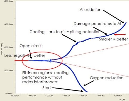
Figure 8 - Fitting Tafel data with the Butler-Volmer equation: Raw data.
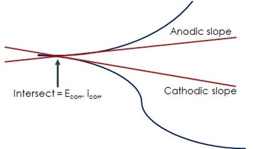
Figure 9 - Fitting Tafel data with the Butler-Volmer equation: Tafel slopes, corrosion potential & current.
The simplified plot in Fig. 9 shows relationship of the data to the Butler-Volmer equation, which determines the Tafel slopes which intersect to yield the corrosion potential, Ecorr and current, icorr:12

5. Experimental plan
Our experimental plan is based on the idea that more aggressive pretreatments cause poor coating formation and performance. Thus, we sought a full comparison of the best and worst practices with an aggressive pretreatment condition. Here, and iron-based deoxidizer offers a more aggressive pretreatment than typically recommended. Accordingly, the results for the best process would be indicated by the longest salt fog time to failure with the least pits. The worst process would produce the shortest salt fog time to failure with the most pits. Once these results were established, the goal was to link the best and worst performing processes (via salt fog testing) to their electrochemical behavior, which would be expected to show the same trends and rankings.
5.1 Test panel preparation
Four processes, here referred to as T1, T2, T3 and T4, were evaluated in salt spray, and via the three electrochemical tests outlined above. Five panels of each process type were subjected to salt fog.
The aluminum panels were prepared according to the following protocol:
- Alkaline cleaner
- Double water rinse
- Iron-based deoxidizer
- Double water rinse
- Trivalent chromium conversion coating
- Short DI water rinse
A 24-hour cure time (ambient temperature away from coating line) occurred before salt fog or electrochemical testing.
6. Salt fog and electrochemical results
6.1 Salt fog test results
The results for salt fog testing are shown in Table 2. Process T2 is seen to have performed the best, with the longest salt spray time before failure. Process T3 performed the worst, with the shortest salt spray time and the largest number of pits within that time. Processes T1 and T4 showed the same short salt spray time at 336 hr with fewer pits. The ranking of the process performance in salt spray is T2 > T1 = T4 > T3. This ranking serves as the benchmark for comparison with the three electrochemical analytical tests.
Table 2 – Salt fog results.

6.2 Open circuit potential (OCP)
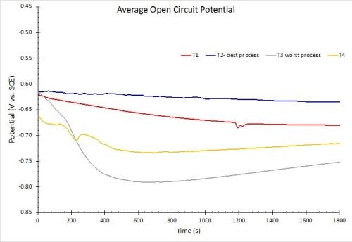
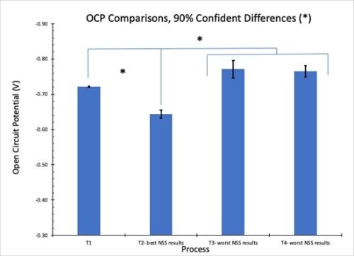
The results for OCP measurements in 1.0M NaCl solution are shown in Fig. 10. Less negative values correspond to greater corrosion resistance. The results in Fig. 10(a) reflect the average for three test samples. These measurements are in accord with the salt spray rankings (T2 > T1 = T4 > T3). When the 90% confidence interval is taken into account, there is no statistically significant difference between processes T3 and T4. However, it should be noted that T3 and T4 exhibited the worst salt spray results of the four processes.
(a)
(b)
Figure 10 - OCP measurements in 1.0M NaCl: (a) average open circuit potential (n=3) versus time to 30 min; (b) OCP process comparisons showing 90% confidence intervals.
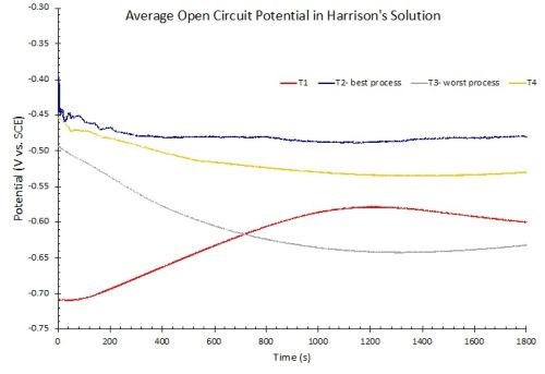
Figure 11 - OCP measurements in Harrison’s solution.
OCP measurements need not be limited to 1.0M NaCl solution. Figure 11 shows OCP measurements of another set of samples immersed in 10% by volume Harrison’s solution, which is an aqueous solution of 3.5% (NH4)2SO4 and 0.5% NaCl. After equilibrium is reached, the rankings are identical to the results in 1.0M NaCl.
6.3 Electrochemical impedance spectroscopy (EIS)
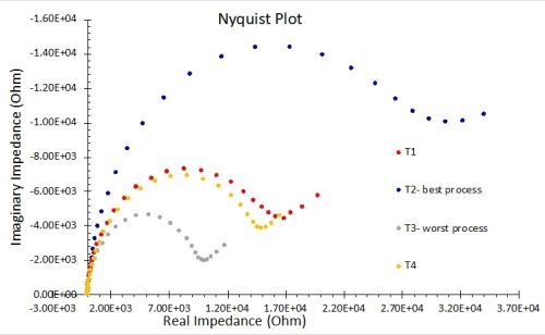
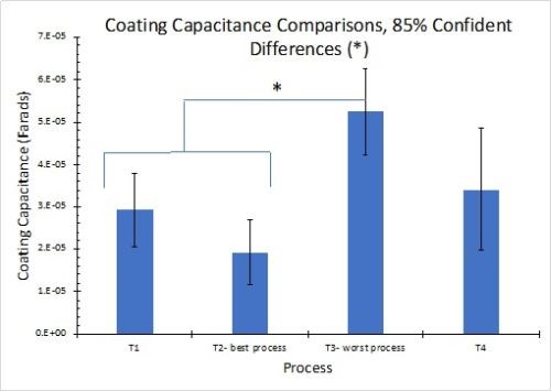
The results for EIS measurements in 1.0M NaCl solution are shown in Fig. 12. The results in Fig. 12(a) reflect the average for three test samples. The larger diameter of the Nyquist plot circle, the greater the resistance polarization, and thus the corrosion resistance. As with the OCP results, these measurements are in accord with the salt spray rankings (T2 > T1 = T4 > T3). Figure 12(b) compares the coating capacitance values, with 85% confidence intervals shown for the three samples in each process. The actual mean for each result is again in accord with the salt spray rankings.
(a)
(b)
Figure 12 - Nyquist plots and equivalent circuit fitting in 1.0M NaCl: (a) Nyquist impedance plots for the four processes (n=3); (b) coating capacitance comparisons showing 85% confidence intervals.
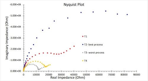
Figure 13 - EIS measurements in Harrison’s solution.
As with the OCP study, measurements using Harrison’s solution as an electrolyte were conducted. As shown in Fig. 13, the Nyquist diameters again rank the measured resistance polarization in the benchmark order determined by salt fog testing, with greater spread between samples.
6.4 Tafel measurements
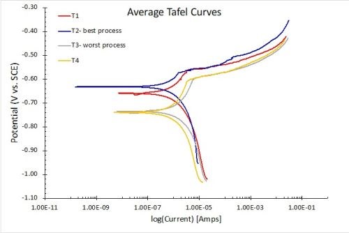
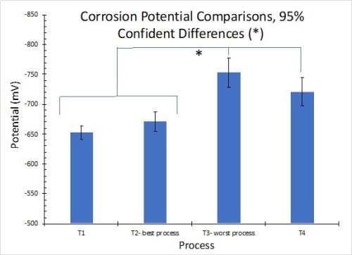
The results for Tafel measurements in 1.0M NaCl solution are shown in Fig. 14. The results in Fig. 14(a) reflect the average for three test samples. The lower the current flow at open circuit potential, the higher the corrosion resistance. As with the other electrochemical measurements, the results of the corrosion “plateau” portion of the curves are in accord with the salt spray rankings (T2 > T1 > T4 > T3). The open circuit current clearly shows the T1 process to be superior. Figure 14(b) compares the Ecorr values, with 95% confidence intervals shown for the three samples in each process. The results confirm the two worst processes, T3 and T4.
(a)
(b)
Figure 14 - Tafel Plots with Butler-Volmer Fitting in 1 M NaCl: (a) average Tafel curves for the four processes (n=3); (b) corrosion potential comparisons showing 95% confidence intervals.
7. Summary
The salt fog and electrochemical results in 1.0M NaCl are summarized and compared in Table 3.
Table 3 - Salt fog results compared to electrochemical measurements in 1.0M NaCl.

All electrochemical measurements lined up well with the benchmark salt spray performance. The open circuit potential (OCP) measured most positive for the best process and most negative for the worst. For the electrochemical impedance spectroscopy (EIS), polarization resistance was highest for the best process and lowest for the worst, while coating capacitance was lowest for the best process and highest for the worst. In the Tafel study, corrosion current was lowest for the best process and high for the worst, while the corrosion potential was most positive for the best process and most negative for the worst. The electrochemical measurements (specifically the polarization resistance and open circuit potential) could better differentiate between processes than the salt spray performance.
8. Conclusions
In the benchmark salt fog testing, the four ranked processes for time in salt spray and pit numbers were T2 > T1 = T4 > T3. For electrochemical testing the ranking was the same for the various electrochemical parameters measured (T2 > T1 > T4 > T3). Processes T1 and T4 were easily separated and ranked using the electrochemical analysis. This excellent correlation shows that electrochemistry can be used as a predictor of salt fog performance.
9. Future electrochemical testing
Future work is planned to determine the best conversion coating processes on different types of aluminum alloys (5052, 6061, 7075) and different light metals (Mg, Zn/Ni). This work will enable more rapid procedures for product reliability control for new products. More comprehensive study can link the exact time in salt spray to electrochemical performance for global cutoffs on coating performance. Finally, different pretreatments can be compared to determine the best performing full process rather than just optimizing one step of the pretreatment. The key is that time is saved to allow more comprehensive testing.
10. References
1. K.J. Bundy, M. Bricka & A. Morales, “An Electrochemical Approach for Investigating Small Arms Munitions in Firing Ranges,” Proc. HSRC/WERC Joint Conference on the Environment, May 1996: https://engg.ksu.edu/HSRC/96Proceed/bundy3.pdf.
2. V. Lins, et al., “Corrosion Behavior of Experimental Nickel-Bearing Carbon Steels Evaluated using Field and Electrochemical tests,” REM - International Engineering Journal, 71 (4), 613-620 (2018): http://www.scielo.br/scielo.php?script=sci_arttext&pid=S2448-167X2018000400613.
3. S. R. Taylor, et al., “The Prediction of Long-term Coating Performance from Short-term Electrochemical Data, Part I. Inhibited Aerospace Coating Systems - Comparison to Salt Spray Data,” Trans. ECS, 24 (1) 185-196 (2014): Abstract: https://iopscience.iop.org/article/10.1149/1.3453616.
4. J. Huetter, “Update: Major Types of Automotive Aluminum Corrosion,” Repairer Driven News, Society of Collision Repair Specialists (SCRS), Mechanicsville, VA, June 5, 2018; https://www.repairerdrivennews.com/2018/06/05/the-three-major-types-of-automotive-aluminum-corrosion/.
5. Anonymous, “1988 - The Aloha Incident,” https://corrosion-doctors.org/Aircraft/Aloha.htm.
6. NTSB Press Release, December 22, 2005; https://web.archive.org/web/20111019164744/http:/www.ntsb.gov/news/2005/051222a.htm.
7. A.J. Bard, et. al., Electrochemical Methods: Fundamentals and Applications, 2nd ed., John Wiley and Sons, Inc., New York, 2001; pp 226-260.
8. “The Basics of Electrochemical Impedance Spectroscopy,” Gamry Instruments, Warminster, Pennsylvania; https://www.gamry.com/assets/Uploads/resources/The-Basics-of-EIS.pdf.
9. “Physical Electrochemistry & Equivalent Circuit Elements,” Gamry Instruments, Warminster, Pennsylvania; https://www.gamry.com/assets/Uploads/resources/The-Basics-of-EIS-Part-2.pdf.
10. “Common Equivalent Circuit Models,” Gamry Instruments, Warminster, Pennsylvania; https://www.gamry.com/assets/Uploads/resources/The-Basics-of-EIS-Part-3.pdf.
11. “EIS of Coated Metals,” Gamry Instruments, Warminster, Pennsylvania; https://www.gamry.com/assets/Uploads/resources/The-Basics-of-EIS-Part-4.pdf.
12. “Polarization Curves: Setup, Recording, Processing and Features,” PalmSens, Houten, Utrecht, The Netherlands, https://www.palmsenscorrosion.com/knowledgebase/polarization-curves/.
About the authors

Dr. Catherine Munson is a Research Chemist at Chemeon Surface Technology LLC . A graduate of Colorado State and Michigan State universities, Dr. Munson is an expert in trivalent zirconate chemistries and has had an immediate impact on Chemeon’s core competency. Dr. Munson was a key member of the team that conducted a recent study and subsequent paper on Chemeon TCP (hexavalent-free) as an anodic seal to replace sodium dichromate/dilute chrome seals. Her 2017 Ph.D. dissertation, “Electrochemical and Material Characterization of a TCP Conversion Coating on Aluminum Alloy 7075-T6,” studies the application mechanisms and efficacy of TCP conversion coatings. She is currently leading product research and development at Chemeon, working to provide new and improved light-metal coating systems to customers. She recently was named to the Products Finishing 40 under 40 in 2018.

Dr. Sjon Westre, as Vice-President of Technology, leads Chemeon’s development of environmentally responsible coating and seal alternatives to hexavalent chromium for use on light metals. His focus includes the creation and optimization of new conversion coating and anodizing chemistries and processes, development of analytical procedures, and management of the Chemeon Laboratory, Training Center and Technical Support Group. He received his Ph.D. in Physical Chemistry from The University of California at Davis and a B.S. degree in Chemistry with a Physics minor from Cal State, Sacramento. Prior to joining the Chemeon team, Dr. Westre spent the last decade as Senior Scientist for Modern Industries in Phoenix where Chemeon chemistry and technology has been in use for a number for years. Prior to that, Dr. Westre was Technical Director of METALAST International LLC. Prior to that Dr. Westre was Research Scientist at Mosaic Industries in Silicon Valley where he developed custom hardware and software for trace gas detection instruments. Sjon began his career as an analytical chemist at Analytical Associates, Inc. in Sacramento. Dr. Westre has published numerous technical papers in the fields of Molecular Physics and Analytical Chemistry. He also lectured at technical conferences as well as acted as an instructor for undergraduates at UCD.
*Compiled by Dr. James H. Lindsay, Technical Editor - NASF
** Corresponding authors:
|
Dr. Catherine Munson Research Chemist CHEMEON Surface Technology 2241 Park Place Ste B Minden, NV 89423 Phone: 775-301-5721 Email: cmunson@chemeon.com |
Dr. Sjon Westre Vice President of Technology CHEMEON Surface Technology 2241 Park Place Ste B Minden, NV 89423 Phone: 775-301-5720 Email: swestre@chemeon.com |
*** Gamry Instruments, 734 Louis Drive, Warminster, Pennsylvania 18974.
Related Content
Electroplating in the Context of Worldwide Nanotechnology Initiatives: A Heritage Paper
In the first part, a summary is presented on recently established nanotechnology initiatives in various countries around the world. Program funding levels and core activities will be compared to provide a basis for assessing business opportunities for various industries. The second part of the paper looks at specific examples of nanostructures made by electrochemical methods currently at various stages in their development, or already in use.
Read MoreLooking to the Future of Finishing
Products Finishing takes a look at some of the ways the finishing industry is investing in workforce development and educational initiatives.
Read MoreDevelopment of a Novel Hexavalent-Chromium-Free Aluminum Sacrificial Paint
Hexavalent chromium is a known carcinogen, repro-toxin, and mutagen. Its elimination is of high importance to the aerospace industry, which has struggled to find high performing alternatives. Legacy aluminum sacrificial paints have traditionally utilized hexavalent chromium to prevent corrosion and coatings which are equal to or better than have been difficult. This first paper discusses the novel process from the supplier point-of-view.
Read MorePlating, Anodizing Equipment for Variety of Applications
Titan Metal Fabricators Titan Metal Fabricators, Rightech Fabrications and Optimum Anode Technologies are leading suppliers of equipment for the plating and anodizing industries.
Read MoreRead Next
A ‘Clean’ Agenda Offers Unique Presentations in Chicago
The 2024 Parts Cleaning Conference, co-located with the International Manufacturing Technology Show, includes presentations by several speakers who are new to the conference and topics that have not been covered in past editions of this event.
Read MoreEducation Bringing Cleaning to Machining
Debuting new speakers and cleaning technology content during this half-day workshop co-located with IMTS 2024.
Read MoreEpisode 45: An Interview with Chandler Mancuso, MacDermid Envio Solutions
Chandler Mancuso, technical director with MacDermid Envio discusses updating your wastewater treatment system and implementing materials recycling solutions to increase efficiencies, control costs and reduce environmental impact.
Read More


