Corrosion-Current Data for Nickel-Chromium Couples
When nickel electroplate is coupled with chromium, a high current density and corrosion rate at the anode, usually nickel, are favored by a high electrolyte concentration, a high temperature and a low nickel-to-chromium area ratio.
ABSTRACT
When nickel electroplate is coupled with chromium, a high current density and corrosion rate at the anode, usually nickel, are favored by a high electrolyte concentration, a high temperature and a low nickel-to-chromium area ratio. The passivity of the chromium, which is dependent upon aging conditions, has a profound influence on the corrosion current. The information in this paper, based on research conducted for the American Zinc Institute, resolves some anomalies that obscured factors bearing on the corrosion of electroplated zinc die castings.
Introduction
Discontinuities in decorative chromium are recognized as the principal sites at which corrosion begins on electroplated zinc die castings exposed to outdoor weathering. Corrosion of bright nickel is accelerated by plating chromium over it.1 The rate of nickel corrosion under pores and cracks in the chromium plate is affected by several factors and cannot be precisely predicted for a specific system in a given environment.
Electrode-potential and current data for nickel-chromium couples in some recent papers and reports2-4 pose some anomalies that obscure an interpretation of corrosion phenomena for copper-nickel-chromium composites. Specifically, some of these data indicated that chromium electrodes were more active than electrodeposited nickel under conditions that should show a greater activity for the nickel. In other cases, chromium was slightly passive to nickel, but the currents reported for nickel-chromium couples were insufficient to explain the much greater nickel corrosion rates observed when nickel- and chromium-plated parts are exposed outdoors.
One objective of the research program conducted for the American Zinc Institute was to develop electrode-potential and corrosion-current data that would resolve the anomalies, provide a better understanding of the mechanism of corrosion, and create a reliable basis for devising improved plating procedures. This study began with the development of electrode-potential data for eleven different nickel deposits.
The electrochemical activity of electrodeposited nickel
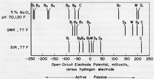
Open-circuit, electrode potentials of seven bright-nickel deposits, three semi-bright-nickel plates and Watts-type nickel spanned broad ranges in each of five electrolytes. Figure 1 shows the steady-state potentials in acidified, sodium chloride solutions. Broad ranges were reported previously for nickel potentials in Corrodkote slurry2 and a solution of sodium chloride and hydrogen peroxide.4
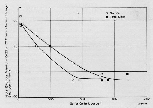
The relative activities of eight representative nickel deposits in CASS solution correlated with their sulfide and total sulfur contents, are shown in Fig. 2. This correlation confirms, in a quantitative fashion, the distinction observed previously for "sulfur-free" and "sulfur-containing" nickel deposits.2 In Fig. 2, the same correlation exists for total sulfur as for sulfide sulfur.
Mechanical polishing and mechanical buffing increased the activity of bright-nickel and Watts-type nickel electrodes. The shift to a more active condition caused by mechanical working was 40 or 50 mV. As a result, nickel anodes corroded at a faster rate when coupled with passive chromium after their surfaces were mechanically worked. Thus, buffed Watts-type nickel was similar in electrochemical behavior to the less-active bright-nickel deposits.
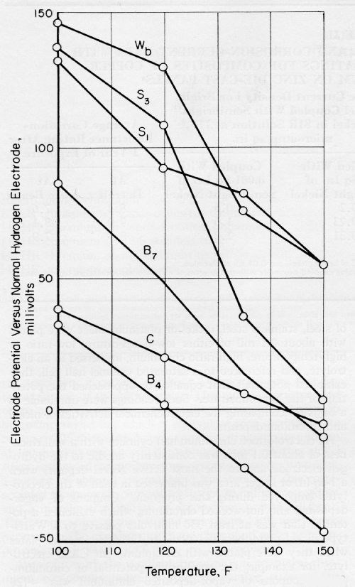
An increase in the temperature of CASS electrolyte shifted the nickel potentials towards an active condition, as shown in Fig. 3, but only minor changes occurred in their order. The temperature coefficient of the potential of S3 was -2 1 mV/°F, and the coefficient for other nickel deposits was about -1.7 mV/°F. The copper potential had a lower coefficient of only -0.88 mV/°F. An extrapolation of the data in Fig. 3 indicates that copper would be more active than any of the bright-nickel plates at low temperatures.
Figure 4 shows potential data for nickel deposits in neutral salt solution and in dilute electrolytes simulating the compositions of rain waters. These simulated rain-water compositions are given in Table 1. Their pH and that of nearly all of the rain waters reported in the literature5-9 was less than 7.0. Thus, potential and current data for neutral solutions are not so pertinent as they are for acid solutions.
Table 1 - Composition and conductivities of simulated rain waters.
Composition | Simulated marine rain water | Simulated industrial rain water |
Potassium chloride, mg/L | 0.22 | 0.30 |
Sodium chloride, mg/L | 10.1 | None |
Ammonium nitrate, mg/L | 0.16 | None |
Calcium sulfate, CaSO4·2H2O, mg/L | 1.63 | 4.30 |
Magnesium sulfate, MgSO4·7H2O, mg/L | 0.86 | 5.15 |
Sodium sulfate, mg/L | None | 0.92 |
Ammonium sulfate, mg/L | None | 1.19 |
Hydrochloric acid, mg/L | 2.15 | None |
Nitric acid, mg/L | None | 30.5 |
Sulfuric acid, mg/L | None | 147.0 |
Total chlorides, meq/L | 0.236 | 0.004 |
Total nitrates, meq/L | 0.002 | 0.484 |
Total sulfates, meq/L | 0.026 | 3.123 |
Total cations, meq/L | 0.264 | 3.611 |
pH | 4.30 | 2.53 |
Conductivity, ohm-1 cm-1 × 10⁻⁶ | 45 | 590 |
The difference in the potentials of the most active and the most passive nickel plates was about 0.3 V in the simulated marine rain water (SMR). The electromotive force series for these nickel deposits spanned a range of 0.12 V in the simulated industrial rain water (SIR).
The potentials for the individual nickel plates were ordered in about the same manner in each of the salt and simulated rain-water solutions. The semi-bright and Watts-type nickel plates were passive to all of the bright nickel plates, as would be expected from the results of accelerated-corrosion and outdoor-weathering studies. In the selection of a duplex nickel system, a random combination of a semi-bright and a bright-nickel plate might be inappropriate for achieving the benefits recognized for specific duplex nickel systems. A combination of Semi-bright Nickel 2 and Bright Nickel 7, for example, was less efficacious than duplex systems S2B3 and S3B4. The small potential difference between S2 and B7 evidently is insufficient to inhibit corrosion pitting effectively in the semi-bright-nickel plate. Data on outdoor corrosion resistance for these duplex systems are given in Table 2.
Table 2 - Correlation of electrode potential and corrosion current data with outdoor corrosion performance ratings for composites of copper, duplex nickel and chromium on zinc die-cast panels.a
Duplex Nickel System | Open circuit potential between semi-bright and bright nickel deposits | Anode current density for bright nickel coupled with semi-bright nickel in SIR solution at 77°F,b μA/in.2 | Average corrosion resistance rating after one year of exposure | ||||
In CASS solution | In acid salt solution | In SIR | Coupled with 0.01 in.2 of semi-bright nickel | Coupled with 0.001 in.2 of semi-bright nickel | At Detroit | At Kure Beach | |
S2B7 | 40 | 40 | 10 | 0.2 | 0.6 | 8.2 | 7.6 |
S2B3 | 100 | 130 | 50 | 0.23 | 1.6 | 9.0 | 8.1 |
S3B4 | 100 | 110 | 80 | 0.31 | 2.0 | 8.9 | 7.9 |
(a) Each composite consisted of 0.4 mil of copper, 0.55 mil of semi-bright nickel, 0.25 mil of bright nickel and 0.01 mil of chromium. (b) Current data for 1.0 in.2 areas of electroformed, ¼-inch diameter, bright nickel tubing coupled externally with smaller areas of electroformed semi-bright nickel tubing. | |||||||
Replacing one-half of the sulfate ions in the SIR solution with sulfite ions had activating and equalizing effects on the potentials of the nickel plates. They spanned a range of only 0.035 V, and their average potential was -170 mVSHE. A 0.1% solution of sulfur dioxide at 120°F also had an equalizing effect; the most active and the most passive nickel plates exhibited potentials of -110 and -80 mVSHE, respectively, differing by only 30 mV. These potential relationships indicate that the sulfur dioxide-accelerated corrosion test would fail to distinguish an efficacious duplex nickel system from a single bright-nickel layer. This disadvantage of the sulfur dioxide corrosion test was recognized previously.10
The potential of copper was midway in the range of the nickel potentials in the salt solutions. Copper assumed a potential in the sulfur dioxide solutions that was 0.3 to 0.4 V more passive than the most passive nickel deposits. This relationship shows why copper corrodes slowly in the sulfur dioxide test and why copper-nickel-chromium composites appear superior to nickel-chromium composites when subjected to this test.11
Potential data for chromium electrodeposits
The electrodes employed for measuring the potentials of nickel plate were 1-in.2 areas of electronickel foil or a 1-inch-long by ¼-inch-diameter, thin-walled electroformed tube. Because it was considered impractical to electroform chromium foil or thin-walled tubing, chromium deposits on nickel and other substrates were investigated. When 1-in.2 areas of steel, stainless steel, nickel or platinum sheet were plated with about 0.1 mil of either low-temperature, low-ratio or high-temperature, high-ratio chromium, immersed in an electrolyte, and referenced to a saturated calomel half cell, they exhibited potentials that equaled or approached the potentials of the bare substrate. Such readings were unreliable as a basis for comparing the electrochemical activities of nickel and chromium deposits.
An electroformed chromium half cylinder with a wall thickness of about 0.1 inch was consistently anodic to the hydrogen electrode and to the most active nickel deposit, when a 1-in.2 or larger area was immersed in each of the electrolytes employed during this program. Coupons of vapor-deposited and hot-worked chromium, which exhibited a potential that was at least 350 mV passive to a Watts-type nickel plate, became anodic to the active nickel plates when they were plated with chromium. In CASS electrolyte, for example, the equilibrium potential of chromium-plated coupons of vapor-deposited chromium was -120 mV (100 mV anodic to the most active bright nickel).
To check the reliability of these measurements, potential data were derived for smaller areas covered with a single drop of electrolyte, into which a small calomel electrode was suspended. Potential readings with a calomel probe generally spanned a broad range, depending on the locations of different drops of electrolyte. Representative readings for several chromium electrodes are shown in Table 3.
Many very passive spots were located on the electroformed chromium electrode with the calomel electrode probe. Other spots displayed a more active condition approximating the potential readings for larger, 1-in.2 areas. Microscopic examination of the surface indicated that the passive spots contained fewer and wider cracks than the active areas. Passivity also was detected at some areas of the chromium-plated electrodes. For example, a potential of 240 mV (passive to the hydrogen electrode) was determined for several spots on a Watts-type nickel foil plated with bright nickel and high-temperature, high-ratio chromium. Yet, other spots were even more active than the bright nickel under the chromium. These observations indicated that conditions were not satisfied for maintaining chromium in a passive condition at areas containing a relatively large proportion of discontinuities. On the other hand, areas approaching a pore-free and crack-free condition were consistently passive.
When one end of a sliver sheared from electroformed nickel was suspended in a drop of CASS electrolyte on the surface of the electroformed chromium specimen and coupled with the specimen, a current of about ½ μA was detected at one of the active sites. This current corresponded to an anode current density for the chromium of about 50 μA /in.2, which is equivalent to a corrosion rate of about 0.25 μ-in./hr, assuming chromium dissolution at 100% efficiency in the trivalent state. With a nickel sliver suspended in another drop covering passive chromium, a current of about 1 μA was detected; this corresponded to an anode current density of 20 mA/in.2 and a nickel-corrosion rate of approximately 0.15 mil/hr. The temperature of the solution was about 120°F in each experiment. The exposed nickel and chromium areas were approximately 0.00005 and 0.01 in.2, respectively.
Table 3 - Equilibrium potentials for chromium electrodes in CASS electrolyte.
Electrode | Potential in CASS solution at 77°F, mVSHE. | |||
Chromium, 1.0 in.2 area | Chromium, 0.01 in.2 area | Substrate, 1.0 in.2 area | ||
Most active reading | Most passive reading | |||
Electroformed chromiumb | -80 | -100 |
460c | ----- |
LTLR chromium on vapor-deposited chromiumd | 120 | -20 | 290 | 630 |
HTHR chromium on vapor-deposited chromiumd | 320 | 160 | 420 | 590 |
HTHR chromium on 18-8 stainless steeld | 150 | 260 | 300 | 50 |
HTHR chromium on active bright nickeld | -10 | -190 | 240 | 70 |
HTHR chromium on platinumb | 550 | 500 | 580 | 530 |
(a) The area of the tip of the calomel electrode immersed in a single drop of electrolyte was 0.006 in.2 (b) Aged indoors for about 3 months and scrubbed with magnesium oxide. (c) The passive readings corresponded to areas where width of the cracks had been enlarged by some undetermined etchant. (d) Exposed to a laboratory atmosphere for about 3 weeks; these chromium deposits were about 0.1 mil thick. | ||||
Aging effects for chromium plate
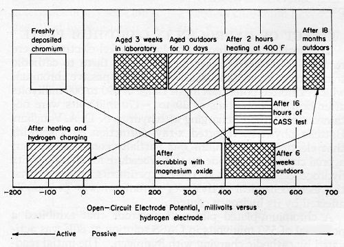
Freshly deposited chromium on nickel is consistently anodic to nickel, according to potential data derived with a calomel electrode probe. Steady-state potentials for chromium deposited in high-temperature, high-ratio and in low-temperature, low-ratio solutions were -50 to -150 mV (anodic to the hydrogen electrode) in CASS solution. No passive spots were located. On the other hand, the chromium on panels exposed outdoors for 15 months was consistently passive, except for spots where pores or cracks were obvious. The passive readings were 620 to 680 mV. Potential measurements at spots coinciding with obvious discontinuities ranged from 20 to 80 mV, which approximates the potential of the bright nickel under the chromium. The potential of chromium on copper and nickel-plated zinc-alloy panels exposed outdoors for 10 days ranged from 240 to 390 mV. After six weeks outdoors, the potentials were between 400 and 540 mV.
Freshly deposited chromium was passivated by color buffing. After two light passes, potential readings ranged up to 400 mV, relative to the normal hydrogen electrode.
Exposure to CASS fog had a distinct passivating influence. After 16 hr, representative potential readings were 430 to 540 mV, excluding areas containing obvious discontinuities. After 90 hr of CASS, representative readings ranged from 470 to 530 mV. Even the magnesium oxide scrubbing step that is customary for cleaning plated parts prior to CASS testing had a passivating influence that appeared to be almost as effective as the 16-hr CASS test which includes such a cleaning step. Representative readings after magnesium oxide scrubbing were between 200 and 420 mV. The potentials for passive chromium areas ranged from 150 to 250 mV on panels subjected to 16 hr of CASS with no prior cleaning. The greater degree of passivity for the scrubbed chromium accounts for the greater amount of corrosion observed for plated parts cleaned with magnesium oxide before exposure to CASS.12 Any exposed nickel, which is anodic to passive chromium, corrodes at a higher rate as the passivity of the chromium is increased.
Potential readings for several sets of nickel and chromium panels aged 18 months indoors under a protective-paper wrapping showed only active chromium (-10 to -80 mV) on most of the panels. An intermediate degree of passivity ranging from 110 to 140 mV was detected on the other panels aged indoors. No reading was greater than 140 mV. Electrode potentials for chromium on panels exposed three weeks in the laboratory were between 90 and 240 mV. These aging effects are shown graphically in Fig. 5.
After heating freshly deposited chromium on nickel and vapor-deposited chromium to 400°F in a reducing atmosphere, a high level of passivity was detected with a calomel probe. Potential measurements were in the range of 390 to 600 mV after a two-hour heat treatment. This result indicated that the hydrogen content of freshly deposited chromium prevented the chromium from becoming passive. After a substantial amount of hydrogen was outgassed from the chromium-plated electrodes, the chromium surfaces became passive.
Effect of hydrogen in chromium plate
The heat-treated, chromium-plated, nickel electrodes were restored to an active state by subjecting them to cathodic treatment in an alkaline solution. For the passive chromium which exhibited potentials in the range of 390 to 600 mV after heating, potentials of 20 to -170 mV were obtained after cathodic charging with hydrogen. D.A. Vaughan, Battelle physicist, reported x-ray diffraction data showing that electrolytic chromium was partially converted to hexagonal chromium hydride by this procedure for charging with hydrogen. The results of these experiments confirmed that the electrochemical activity of chromium was profoundly affected by its hydrogen content.
A chromium-plated platinum electrode that exhibited a potential of 550 mV in CASS solution at 80°F was activated by cathodic charging with hydrogen. The initial reading after charging was about 20 mV. However, hydrogen egressed too rapidly to detect a steady-state condition, and the electrode potential gradually increased to about 400 mV. The potential of an unplated platinum electrode was unchanged after a similar cathodic treatment.
Chromium deposited on nickel in high-temperature baths usually was more active initially than chromium deposited in low-temperature baths. Furthermore, the transition at room temperature from an active towards a passive condition was slower for high-temperature chromium than it was for chromium produced at low temperatures. After passivation and reactivation by cathodic charging, high-temperature chromium was more active than low-temperature chromium. These differences in behavior are related to the number of discontinuities in the deposit. The egress of hydrogen evidently was faster from low-temperature chromium, which contained a larger number of discontinuities.
An attempt was unsuccessful in extending these observations to chromium with a microscopic system of cracks numbering more than 1000 per linear inch. Reliable potential data for microcracked chromium could not be obtained by suspending a calomel probe in a drop of electrolyte, because a single drop spanned more than 100 cracks. The crack patterns of microcracked systems have been described in several publications.4,13-15
Corrosion currents for nickel-chromium couples
Current measurements between nickel and chromium electrodes shorted externally revealed greatly different values, depending on (1) the composition and pH of the electrolyte, (2) its temperature, (3) the activity of the chromium deposit, (4) the activity of the nickel deposit and (5) the nickel-to-chromium area ratio.
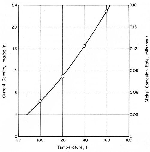
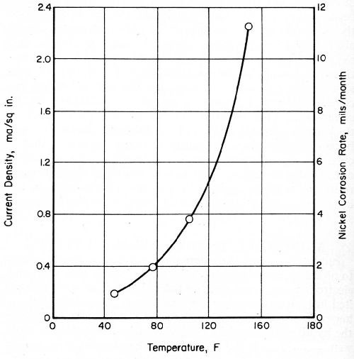
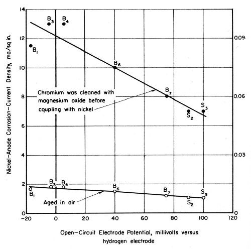
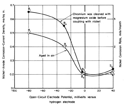
Current-density values for a bright-nickel anode coupled with passive chromium were considerably greater in CASS solution than they were in a simulated rain water (SIR), as shown in Figs. 6 and 7. The same bright-nickel and chromium electrodes were employed to develop both sets of data. Their areas were 0.012 and 1.0 in.2, respectively. The chromium-plated, platinum electrode exhibited open-circuit potentials of 480 mV in SIR solution and 550 mV in CASS electrolyte, at 77 and 120°F, respectively.
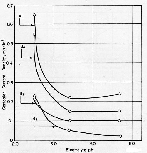
Corrosion current densities for nickel coupled with chromium decreased with an increase in the pH of simulated industrial rain water from 2.5 to 3.4, but leveled off above a pH of 3.4. Table IV and Fig. 8 show the pH dependency of corrosion current densities. As shown in Table 4, the electromotive force series for active and passive nickel plates was increased in breadth as pH was increased.
Table 4 - Effect of the pH of simulated industrial rain water on the open circuit electrode potentials and corrosion current densities of nickel and on the open circuit electrode potential of chromium.
Electrodeposit | Open-circuit electrode potentials, mVSHEa | Corrosion current density for Ni anode coupled with Cr, mA/in.2 b | ||||
pH 2.5 | pH 3.4 | pH 4.7 | pH 2.5 | pH 3.4 | pH 4.7 | |
Bright nickel 1 | -80 | -80 | -110 | 0.65 | 0.22 | 0.24 |
Bright nickel 4 | -30 | -50 | -70 | 0.55 | 0.15 | 0.15 |
Bright nickel 7 | -10 | 10 | -50 | 0.21 | 0.10 | 0.10 |
Semi-bright nickel 3 | 40 | 110 | 150 | 0.23 | 0.05 | 0.02 |
HTHR Cr on Pt | 480 | 480 | 340 | ----- | ----- | ----- |
(a) The negative sign signifies active nickel, relative to hydrogen electrode. A calomel electrode was employed as the reference electrode. The chromium was scrubbed with magnesium oxide prior to use. (b) The area of each nickel specimen was 0.01 in.2 The nickel-to-chromium area ratio was 0.01. | ||||||
The activity of the chromium electrode has considerable influence on the magnitude of the corrosion current for a nickel-chromium couple. The pertinent data shown in Fig. 9 were derived by immersing a sliver sheared from a bright-nickel foil into single drops of electrolyte on a chromium surface. One of the curves corresponds to current measurements for a 0.004-in.2 area of nickel and the other to measurements for a 0.00006-in.2 area. In each case, active chromium was anodic to nickel, but corrosion currents were very low. When the same nickel electrodes were coupled with passive chromium, the nickel anode current densities varied considerably, depending on the degree of chromium passivity and the nickel-to-chromium area ratio.
The activity of the nickel electrodeposit had less influence than that of the chromium on the magnitude of the corrosion current for nickel-chromium couples. However, the current values for couples including active bright nickel were slightly greater than the corrosion currents observed for the relatively passive nickel deposits. Figures 10 and 11 show corrosion currents for nickel-chromium couples as a function of the open-circuit potentials of the nickel electrodeposits in simulated industrial rain water and CASS solution, respectively.
Two curves appear in Figs. 10 and 11. One curve in each figure corresponds to values obtained for couples including a passive chromium electrode stored in the laboratory for about 2 months. The values in CASS at 120°F (Fig. 11) are lower than those shown at the same temperature in Fig. 6. The high corrosion-current values shown by the other set of data in Fig. 11 were obtained after the chromium electrode was cleaned by scrubbing it with magnesium oxide. Although this cleaning caused no change in the open-circuit potential of the chromium, corrosion currents for nickel-chromium couples in CASS solution were increased about sevenfold. This increase is attributed to a rate increase associated with the removal of a relatively thick oxide film that has a high resistance to current flow. The electron conductance characteristics of oxygen-containing films on chromium have been described by Weidinger and Lange.16
The effect of changes in the nickel-to-chromium ratio
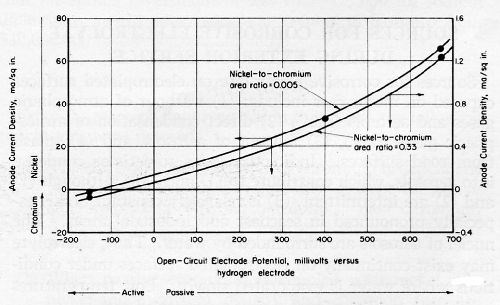
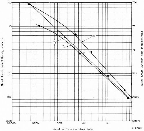
The anode current density for nickel-chromium couples was greatly increased by decreasing the nickel-anode area and the nickel-to-chromium area ratio. Representative data for chromium couples with three nickel deposits in simulated rain water are shown in Fig. 12. The same passive chromium electrode was employed to develop all of the data.
Differences in the corrosion rates for active and passive nickel electrodeposits were almost insignificant, by comparison with the very much larger differences resulting from changes in the nickel-to-chromium area ratio. The calculated corrosion rate corresponding to the maximum observed corrosion current was about 750 μ-in./hr (0.75 mil/hr), for a nickel-to-chromium area ratio of 0.00005. This corrosion rate is almost ten times the corrosion perforation rate observed in CASS fog at the same temperature (120°F) for bright nickel under the pores in 0.01 inch of chromium. Yet, a nickel-to-chromium area ratio of 0.00005 is larger than the ratio that is calculated by assuming 50, 0.05-mil-diameter pores in a square inch of chromium surface. Thus, it appears that not all of the chromium area on plated nickel is an effective cathode area and that only a relatively small chromium area adjacent to a pore is affecting the corrosion current between the chromium and the exposed nickel.
Sources for corrosive electrolyte during exterior service
Sources for corrosive electrolyte on electroplated surfaces exposed on motor cars include: (1) washout of atmospheric gases and aerosols (rain), (2) direct condensation of atmospheric gases (dew), (3) fall out of aerosols and (4) splash from road surfaces. Indirectly, gases sometimes condense into aerosols, which contribute to (1) and (3). Although (1) and (2) are intermittent, (3) is relatively constant and is especially pronounced in seacoast and industrial areas. The nuclei of aerosols are surrounded by water. Thus, electrolyte may exist continually on electroplated surfaces under conditions where water is evaporated slowly. Low temperatures and high humidities favor a slow evaporation rate.
The concentration of corrosive anions (sulfate, chloride, and nitrate) in the electrolyte covering plated parts is increased when the rate of evaporation exceeds the rate of fall out or washout. Mud films containing hygroscopic soils retard evaporation and encourage high anionic concentrations and high rates of nickel corrosion. Automobile owners should be encouraged to remove mud films frequently, but no abrasive should be employed during washing, or the electrically resistant chromium oxide films which retard the corrosion rate of the nickel would be removed.
Washout in seacoast and industrial atmospheres contains relatively high concentrations of chloride and sulfate ions, respectively, and lesser amounts of other anions. Sulfur dioxide gas in the atmosphere is the principal source for sulfate ions. In the water droplets that dissolve the gas, SO2 is quickly oxidized.5 The popular belief that SO2 causes corrosion is inaccurate, because clouds and high humidity in atmospheres with high SO2 contents favor the formation of corrosive, sulfate smogs.
Some authorities consider the combustion products of sulfur-containing fuels and the smelting products of ores as the principal sources for SO2, whereas others believe that airborne soil particles contribute an equal share of SO2 to the atmosphere. Decomposition of organic matter in soils contributes sulfides that are subsequently oxidized to SO2.
Sea-salt aerosols originating from air bubbles bursting in ocean waves are another source for sulfate ions. The sulfate ion concentration in ocean water is 14% of the chloride concentration. Of course, sea-salt aerosols account for nearly all of the chloride ions in aerosols over land and sea. The chloride concentration decreases rapidly from the coastlines to the interior, reaching a concentration of about 3 mg/L in a few miles. At this point, chloride and sulfate ion concentrations in rain water are nearly equal, except for industrial areas, where washout containing 20 mg/L or more of sulfate has been collected. The sulfate ion concentration in the washout from polluted air is one to two orders of magnitude higher than the average concentration over land.5 A sulfate ion concentration as high as 125 mg/L has been detected in sulfate fogs.
The corrosivity of mud and water splash from road surfaces is popularly believed to be increased in the winter when salt is employed for deicing. Data on the chloride ion concentrations of storm sewer collections in Buffalo, New York, support this view.17 Collections in February 1957, averaged more than 6 g/L of chloride and ranged up to 40 g/L. In October 1957 and 1958, chloride concentrations averaged about 1 g/L and ranged up to 12 g/L. Buffalo began to spread twice as much salt during the winter season of 1958 and 1959 as the amount used previously, so it is reasonable to assume that chloride concentrations are now doubled. Practice in other northern cities is not greatly different from that in Buffalo. With such a high chloride concentration, high nickel corrosion rates are understandable.
The high cost of corrosion caused by salt for deicing purposes has prompted consideration of corrosion inhibitors. Several inhibitors were screened by adding them to CASS electrolyte into which bright nickel and passive chromium electrodes were immersed. Corrosion-current data for the couple indicated that sodium dichromate was the most effective inhibitor. A 0.1% addition, based on the anionic concentration, reduced the corrosion current to only five% of that detected when no inhibitor was added. In a dilute copper-free salt solution, a sodium dichromate addition reduced the corrosion current to 25% of the base-line figure with no inhibitor added. Based on salt consumption figures and corrosion cost estimates for Toronto,18 it appears that an annual investment of less than $15,000 for sodium dichromate might save motor car owners in Toronto from $30,000,000 to $38,000,000 annually.
Conclusions
From the research data reported in this paper, the following conclusions were reached:
- The electrochemical activity of chromium is dependent on its age and hydrogen content. Except for active sites coinciding with discontinuities, aged chromium is passive in solutions simulating rain waters and in CASS electrolyte.
- When passive chromium is coupled with nickel, the nickel-anode current density and corrosion rate are greatly affected by the composition of the electrolyte, its temperature and the nickel-to-chromium area ratio. High chloride concentrations, high temperatures, and low nickel-to-chromium area ratios favor high corrosion rates for nickel-anode sites.
- Bright-nickel deposits containing relatively high sulfide and total sulfur contents are more active than semi-bright nickel containing very little sulfur. When passive chromium is coupled with an active nickel deposit, the nickel-anode current density and corresponding corrosion rate are greater than they are for a relatively passive nickel deposit. However, the increase in corrosion rate resulting from an increase in the temperature of the electrolyte or a decrease in the nickel-to-chromium area ratio is far more significant.
- Potential and current measurements with large chromium areas containing large numbers of discontinuities are unreliable for interpreting corrosion phenomenon for electroplated nickel-chromium composites. Chromium areas exposed to the electrolyte should ideally contain no discontinuities for developing reliable information on chromium passivity.
Acknowledgements
The authors acknowledge with appreciation the approval for publication received from the American Zinc Institute-Expanded Research Program, for whom this research was conducted. They are especially indebted to G.R. Schaer, Battelle Memorial Institute, for his suggestions in procedures for conducting some of the potential measurements reported in this paper.
References
- W.A. Wesley and B.B. Knapp, Trans. Inst. Metal Finishing, 31 (1955).
- A.H. DuRose, Tech. Proc. Am. Electroplaters' Soc., 47, 83 (1960).
- D.W. Ernst and F. Ogburn, National Bureau of Standards Reports No. 6253 and 6560 on AES Research Project No. 13, January 1, 1959 and October 1, 1960.
- W.E. Lovell, E.H. Shotwell and James Boyd, Tech. Proc. Am. Electroplaters' Soc., 47, 215 (1960).
- C.E. Junge, "Atmospheric Chemistry," 4, 1-108, Advances in Geophysics, edited by H.E. Langsberg and J. Van Mieghem, Academic Press, New York (1958).
- E. Eriksson, Tellus, 4, 280 (1952); 7, 243 (1955); 9, 509 1957); 11, 375 (1959) and 12, 63 (1960).
- E. Gorham, Tellus, 9, 174 (1957) and 10, 496 (1958).
- T.E. Larson and I. Kettick, Tellus, 8, 191 (1956).
- Anonymous, Tellus, 10, 501 (1958).
- Anonymous, Engineering, 189, 742 (June 3, 1960).
- J. Edwards, Tech. Proc. Am. Electroplaters' Soc., 46, 154 (1959).
- C.F. Nixon, J.D. Thomas and D.W. Hardesty, Tech. Proc. Am. Electroplaters' Soc., 46, 159 (1959).
- W.H. Safranek, H.R. Miller, R.W. Hardy and C.L. Faust, Tech. Proc. Am. Electroplaters' Soc., 47, 96 (1960); Plating, 47, 405 (1960).
- E.J. Seyb, Tech. Proc. Am. Electroplaters' Soc., 47, 209 (1960).
- W.H. Safranek and R.W. Hardy, Plating, 47, 1027 (1960).
- H. Weidinger and E. Lange, Z. Electrochem., 64, 408 (1960).
- K.G. Compton, NACE Technical Committee Report, Corrosion, 16 (12), 105 (1960).
- H.H. Webster, Corrosion, 17 (2), 9 (1961).
Read Next
Episode 45: An Interview with Chandler Mancuso, MacDermid Envio Solutions
Chandler Mancuso, technical director with MacDermid Envio discusses updating your wastewater treatment system and implementing materials recycling solutions to increase efficiencies, control costs and reduce environmental impact.
Read MoreA ‘Clean’ Agenda Offers Unique Presentations in Chicago
The 2024 Parts Cleaning Conference, co-located with the International Manufacturing Technology Show, includes presentations by several speakers who are new to the conference and topics that have not been covered in past editions of this event.
Read MoreDelivering Increased Benefits to Greenhouse Films
Baystar's Borstar technology is helping customers deliver better, more reliable production methods to greenhouse agriculture.
Read More






.jpg;maxWidth=300;quality=90)


