Don’t Believe Everything You Hear - The 22nd William Blum Lecture
This article is a re-publication of the 22nd William Blum Lecture, presented at the 68th AES Annual Convention in Boston, Massachusetts, on June 29, 1981.
by
Dr. Joseph Edwards
Manager, Electrochemistry Research Group
International Nickel Company
Birmingham, England, U.K.
Recipient of the 1980 William Blum AES Scientific Achievement Award
Originally published as Plating & Surface Finishing, 68 (9), 59-64 (1981)
Editor’s Note: This article is a re-publication of the 22nd William Blum Lecture, presented at the 68th AES Annual Convention in Boston, Massachusetts, on June 29, 1981. A printable PDF version is available by clicking HERE.
Dr. Edwards offered these opening remarks before delivering his William Blum Lecture:
“I have had a year to get used to the idea, so it may be difficult for me now to recall to you the pleasure and astonishment I felt at being honored with the AES Scientific Achievement Award. It was like dreaming that Britain had put a man in space, and waking to find it was me. It was an eventuality I had never contemplated, yet I know the award well. I have met nearly all the previous recipients and regard some of them as particular friends. It is a great honor to be accorded membership in such a select club.
"Not long ago I saw a cartoon by W. Hamilton showing two men in the prime of life, financially speaking, holding a conversation. One was saying to the other, 'I have learned a lot in 63 years. But, unfortunately, almost all of it is about aluminum.' With me, it's not aluminum (or even aluminium, as we call it), but I do see his point. In any case, on this occasion, technology is our common ground and technical reminiscence will have to provide my material.
"I needed a theme, and so I chose as my text, 'Don't believe everything you hear.' In many contexts this is advice no one needs - in buying a second-hand car or in reading the paper. There is no better test of this than to talk to a reporter and force yourself to read his article when it appears. It gets you in the pit of the stomach. Much the same feeling as when you discover you have reversed the car over the cat. The feeling passes ... the cat escapes, the article is soon forgotten. In fairness to the journalist, his needs are different from ours. He must capture attention. He has to meet his deadline. Hence his motto: 'Don't get it right, get it written.'
"So, don't believe everything you hear. Let us see how that applies in a technological context."
Electropolishing enigma
I’ll begin with my first electrochemical investigation. I was looking at electropolishing, a process by which a rough, dull metal surface is made smoother and brighter by anodic dissolution. There was no satisfactory explanation of the phenomenon. It was known that polishing did not begin until a little while after the circuit was closed, at a point where the current fell sharply. It was stated that at this point the current density fell more steeply on recessed areas than on projecting areas of the surface, so that current distribution subsequently favored rapid removal of the projections.
It seemed a good idea to demonstrate this change experimentally, so I made an electrode on which I could measure separately the currents on peaks and recesses. It comprised a stack of about 40 copper sheets, each insulated from its neighbor, with alternate sheets connected together in two sets. One edge of the stack was exposed, and this constituted the anode surface.
Part of the surface is shown in Fig. l(a). One set of foils was made anodic in phosphoric acid solution and partially dissolved to give a surface of alternating ridges and grooves (Fig. l(b)). Because the insulation had swelled, it was trimmed back under a microscope, to look like Fig. l(c) or (d). The profile in Fig. 1(d) proved the more satisfactory because it was more stable. It meant that the area of the ridge was now greater than that of the grooves, but this was not important. The ridges would take a higher current, anyway. The question to be answered was how far the ratio of current between ridges and grooves would change when polishing conditions were established.
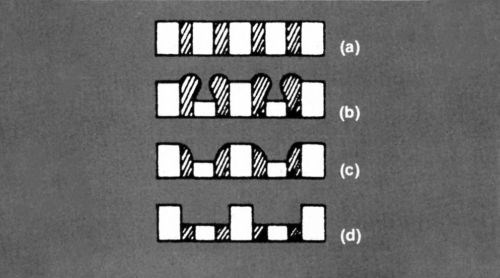
Figure 1 - Surface profiles of composite electrode.
You may have guessed. I switched on my rather primitive cathode-ray oscilloscope and recorded the traces. Both currents fell, steadily at first, then more steeply at the critical point. And (surprise, surprise!) the ratio remained constant throughout. An example is shown in Fig. 2. If you multiply the current in the recessed area by a constant ratio, you get the broken line which almost coincides with the line showing the current through the projecting area. So there is no change in the ratio when polishing conditions are established.
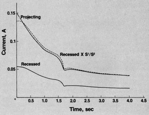
Figure 2 - Current vs. time curve in phosphoric acid solution.
Unexpected results in the laboratory never surprise for long. Within the hour I was telling myself I was a fool not to have seen it before. The sharp drop in current clearly represented the attainment of a limiting concentration of some species participating in the reaction. So, at that point, current distribution ceases to be a purely electrical affair and comes under the control of mass-transfer considerations. But - and this is the key point - provided the surface irregularities are small in comparison with the thickness of the diffusion layer, the electric and diffusion fields are identical in form and follow the same mathematical laws. Therefore no change in current distribution. Q.E.D.
This glimpse of the now blindingly obvious had been a long time in coming - to me, at any rate. Was it possible I was the first to see it? Well, hardly. Christopher Columbus went to his grave believing he was the first to discover America. To be so lucky myself I would have had to die on the spot. I very soon realized that the basic idea - that metal dissolution under polishing conditions was controlled by the varying rate of diffusion from point to point on an irregular surface - had been stated clearly enough some 10 years earlier by W.C. Elmore of Swarthmore College.
However, there was a difference between us on the nature of the diffusing species. It is not germane to my present purpose, so I’ll mention it only parenthetically. He plumped for the copper ions and I for the ions or molecules that solvate them. His particles would be leaving the anode surface and mine approaching it. People probably still don't know whether they are coming or going.
Some theories are not easy to prove or disprove. (These comments are parentheses within parentheses.) Do you remember when the Foundation for Ocean Research claimed that tornadoes are encouraged in the Northern Hemisphere by cars driving on the right side of the road, and causing minicyclones whenever they pass those traveling in the opposite direction? They produce lots of statistics, and I would have to admit that we have far fewer tornadoes in England. But proof? Ogden Nash had a far simpler theory about winds, just as tricky to demolish: He said they were caused by trees waving their branches.
Proof positive
Elmore was clear on diffusion control, but he did not fully explore its consequences or remark on the similarity of form between diffusion and electric fields, which must lead one to expect that smoothing under electropolishing conditions is really no greater than would occur under primary current distribution. It seemed desirable to demonstrate this.
The time was 1951, just 30 years ago, and it was the early days of the long-playing record. A colleague suggested that I use a plain-cut LP record master, electroformed in copper, as a standard rough surface. The Decca Record Company was pleased to oblige me. It was easy enough to take portions of the surface, dissolve away controlled amounts and take sections, so observing the progress of smoothing.
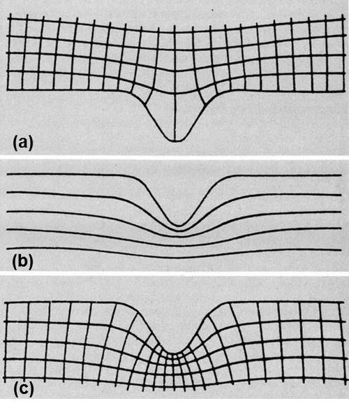
Figure 3 - (a) Current-potential lattice on good surface; (b) successive stages of dissolution; (c) complete lattice representing dissolution of grooved surface.
The next step was to determine the theoretical rate of smoothing. How was this to be done? It could be calculated directly only for the simplest geometries. On a grooved surface it would be necessary to determine the current distribution in some way, perhaps by plotting equipotential lines in an electrolytic trough, or on a sheet of conducting paper, in the neighborhood of an enlarged replica of the surface, and then completing the orthogonal lattice by drawing in the interesting set of current lines. On a single groove it might look like Fig. 3(a).
Current density is the reciprocal of the distance between adjacent current lines, so you can calculate the rate of metal removal at every point. Your troubles are not over. As the surface dissolves, it changes in shape. Consequently, the lattice continuously distorts and the current distribution alters. Successive stages may look something like Fig. 3(b). How are we going to cope with that?
One way is to repeat the calculation ad nauseam. It's called iteration, and is apparently very congenial to computers. Unfortunately, there were none at the time, and I didn't relish turning myself into one. My revulsion from this course paid dividends and I conceived an alternative strategy. It occurred to me that the lines in Fig. 3(b) representing the surface after removal of successive, equal amounts of metal were very like the equipotentials that would be found near a negative replica of the original surface, a ridge instead of a groove. I soon convinced myself that they were identical. Complete the lattice, as in Fig. 3(c), and it is clear that the second set of lines represents the process of dissolution. The distance between them can be made proportional to the current density. The depth dissolved in a given time is proportional to the current density, and, consequently, the mean dimensions of each of these angular figures in the two directions have a constant ratio. The angles of intersection are also right angles. These two characteristics are sufficient to prove the identity of the two lattices.
So I plotted equipotential lines adjacent to both positive and negative replicas of the record surface. They are shown in Fig. 4.
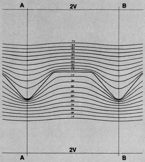
Figure 4 - Equipotential lines near standard surface and its negative replica.
I took not only the record master but its negative as well and did electropolishing trials. Theoretical and experimental lines for both starting surfaces are superimposed in Fig. 5. The fit is very close. It is a convincing demonstration that there is a limiting rate of smoothing that can be achieved, and that this is approached very closely by electropolishing under these conditions.
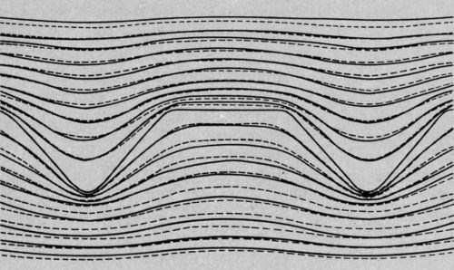
Figure 5 - Theoretical and experimental profiles during dissolution of standard surface and its negative replica (broken lines - theoretical surfaces; continuous lines - experimental surfaces.)
No medals here
I would like to take one more example in some detail, but before doing that, let me mention a few others in which I was involved, but failed to make much of an impression.
Take the theory, current till the mid-1950s, that the breakdown of nickel/chromium coatings was due to porosity of the nickel deposit. I worked on porosity tests and found, like many others, that the less aggressive I was able to make them, the less porosity I was able to detect. At the same time, in outdoor exposure tests, I was observing characteristic corrosion pits. Still, the penny didn't drop. It was left to Wesley and Knapp in 1954 to point out that failure of nickel/chromium deposits was due mainly to corrosion of the nickel at sites of discontinuity in the chromium. In that context, it seems to me, we collectively resisted the obvious for an unconscionably long time.
I took the wrong track for a while in relation to accelerated corrosion tests. Salt and vinegar were fine on chips, but didn't seem an inspired choice for testing decorative deposits. The most aggressive component of the worst industrial atmospheres was sulfur dioxide. Why not try that? We did, but we never got it to work well for the intended application. The acetic acid salt spray and the CASS test, on the other hand, did a good job in most circumstances and have stood the test of time.
Another horse I backed which limped all the way to the post was crack-free chromium. On the face of it, a coating with very few discontinuities seemed a reasonable alternative to one that was full of holes. It has quite a long history, too, and it is ironic now to recall that the earliest objection made to it was to its color - it was slightly bluer than regular chromium. The critics argued that the lack of perfect color match would prevent its use on cars. Ten years later there was every conceivable kind of bright finish on cars, and no one seemed to care about color matching. Another 10 years and, sadly, on many European cars, there are virtually no metallic finishes.
My last case history concerns alkaline batteries. One of the attractions to me in joining Inco was the opportunity to work in new fields, among them that of batteries. The company already had a stake in supplying battery materials, so we concentrated our efforts on electrode design rather than the development of different electrochemical couples.
The trick in electrode design is to dispose the principal components - active mass, conducting support and electrolyte - in the best possible relationship to one another, so that each is most fully utilized, while keeping the overall resistance as low as possible. One way of striving for this is simply by trial and error. We tried instead to elucidate some of the principles underlying electrode design, and in this work I was fortunate to have as my collaborator a very able and versatile technologist, John Whittle. We simulated and idealized the structure of battery electrodes by holding the active mass in a slot between two nickel walls, charging and discharging it from the edge, and exploring the effects of varying the width and depth of the slot over a range of currents. The results gave quantitative indications of the critical dimensions of battery electrodes and led to the conception of a novel electrode structure.
We call the new design CMG (or Controlled Micro-Geometry) electrodes, because their internal dimensions can easily be varied, and the most appropriate values can be chosen for any particular application.
CMG electrodes are made from metallic foil - perforated with a regular pattern of small holes - which is coated with porous active mass and cut into pieces. These are stacked, keeping all the holes in register, and then pressed. Finally, clean areas of all the foils are welded together onto a tag. Figure 6 gives an idea of what a portion of the electrode looks like, at high magnification, on the surface and in section. The holes can be any shape and arranged in any pattern, provided it is regular. Their most important features are the percentage of area they occupy and their distance apart.
When the electrode is immersed in electrolyte, the percentage of hole area determines the ease with which current can flow through the electrolyte to the inner layers of active mass. The larger the hole area, however, the smaller the area to which active mass can be applied, so it is obvious that a balance has to be struck.
The distance the holes are apart determines how far the current has to flow through electrolyte held in the pores of the active mass to charge or discharge those portions that are most remote from the peripheries of the holes. The resistance offered to this current flow is a function of this distance and also of the level of active-mass porosity which affects the cross-section and tortuosity of the current path.
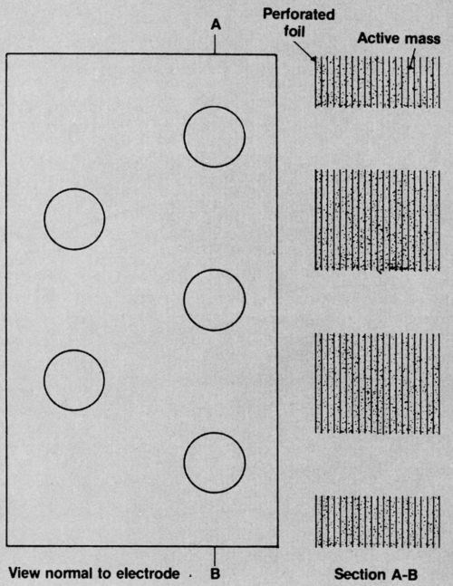
Figure 6 - Diagrammatic views of CMG electrode.
Again, a balance must be struck, for the porosity of the active mass also affects its electronic conductivity. This must maintained at an adequate level so that current can flow from each charge or discharge site to the surface of the foils. The distance this current flows is a function of active-mass thickness, and because most active masses are poor conductors in either the reduced or oxidized form, the layers usually need to be thin. It is a feature of this electrode that when the thickness and porosity have been selected they can be readily held at the preferred values at every point on every foil.
The foils lie exclusively in planes within which current is required to flow, and are thus highly economical current collectors.
The technical challenges, in the case of a nickel hydroxide positive electrode, have all been met, though it took a sizable team of workers 10 years to do it. The foil is electroformed nickel, about 4 μm thick. It is electrolytically perforated in various hole patterns. A common one has holes less than 0.5 mm in diameter and about the same distance apart. Active mass is applied as a slurry, and then dried; a typical thickness at this stage is about 100 μm. These operations are carried out continuously and automatically. The rest is done manually, though it is capable of automation. The foils are cut and stacked, with pins through a few locating holes to register the fine hole pattern. When the required number is reached, the stack is squeezed in a press to adjust to the final thickness and active mass density. Tags are attached, usually by ultrasonic welding.
Two CMG electrodes are shown in Fig. 7. The front one has a 20% hole area and the back one a 13% coarser hole pattern, which is just about visible. A drawback of CMG electrodes made in this way is that they have no transverse strength once they are wetted by the electrolyte. This is no problem if they are held securely in the cell. Some forms of cell construction, however, require the electrodes to be made self-supporting. One way of doing this (though it may sound slightly improbable) is to stitch them, preferably inside a plastic mesh. There is an example of such an electrode in Fig. 8.
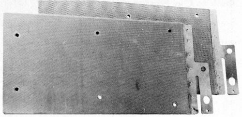
Figure 7 - CMG electrodes.
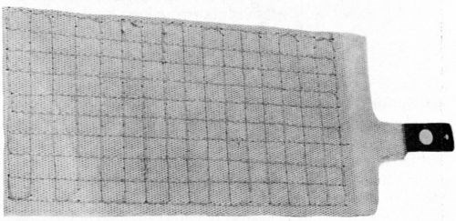
Figure 8 - CMG electrode stitched with plastic mesh.
The advantages of CMG electrodes are increased storage capacity per unit weight and the prospect of significantly lower cost. Unlike most forms of electrode, they can be made with equal facility to any thickness between a fraction of a millimeter and 5 or 6 mm.
Back to our muttons
What has all this to do with my theme? Well, in this investigation we did not set out to test current hypotheses, but it was natural when a new electrode structure had been developed to ask why no one had done it before. Some of the technology was not available, and we had to develop it ourselves, but examination of the prior art showed that people who had made earlier attempts to invent new forms of layered electrodes, with or without holes in them, were hampered by certain misconceptions.
The most important is a prejudice against the compactness, which is an essential feature of our electrodes, but which earlier workers equated with impenetrability. So they took steps to incorporate extra space between layers, by using expanded meshes, or holes with burred edges, by deliberately staggering holes and sometimes by including so-called irrigating material. They justified themselves by saying it was necessary to create a larger interfacial area between active mass and electrolyte, ignoring the fact that the true interface is the internal surface of the porous active mass. In fact, incorporating extra space increases the volume of the electrode and is likely to lead to poor utilization as the active mass is not held firmly enough.
Then there seemed an instinctive desire to arrange for charge or discharge of the active mass to occur perpendicular to the electrode surface, instead of parallel to it as in the CMG electrode. That was another reason why holes were sometimes staggered. One inventor proposed building up a multiple sandwich of active mass and metal, but, then, instead of making holes in it (which no doubt would have been difficult), he proposed cutting off narrow strips and turning them all on edge (which must be very nearly impossible). The basic fallacy is that electric current is somehow reluctant to go around corners. Put like that, it is so ridiculous that I would hesitate to mention it, but for the fact that I was not immune to this heresy myself. Before conceiving the CMG structure, I had always envisaged the ideal electrode as supporting active mass in channels perpendicular to the surface, and had spent some time trying to make nickel honeycombs for this purpose.
I am coming near the end of my piece. T.S. Eliot said of Hamlet, "There is more play here than is needed to tell the story." You may feel I have made the same mistake, with rather less excuse than William Shakespeare.
The message I wanted to convey is not new or profound. All it says really is that technical advances involve a change in our thinking. Challenging current dogma may not benefit your career or save your marriage, but it may be a step towards a new product or process or a better understanding of phenomena. Don't expect always to be right - there is many a glittering hypothesis that turns out to hit the nail right on the thumb. And even false theories have a part to play. Michael Faraday was fond of quoting a saying of Bacon's which puts this very well, so I'll end with it now: "Truth is more likely to arise from error than from confusion."
About the author:
This piece was written at the time Dr. Roberts was announced as the recipient of the 1980 Scientific Achievement Award.
.jpg;maxWidth=600)
Dr. Edwards is a chartered engineer and a fellow of both the Institution of Metallurgists and the Institute of Metal Finishing (IMF). He served as president of the latter between 1975 and 1977 and received the institute's Westinghouse Prize in 1957 and 1963. He is the leader of the British delegation to the International Organization for Standardization and the chairman of the Corrosion and Electrodeposition Committee of the Inter Services Metallurgical Research Council.
He received his B.S. degree in chemistry from the University of Birmingham in 1946, and completed his Ph.D. program in 1949 with a thesis on the kinetics of solid decomposition. He then joined the British Non-Ferrous Metals Research Association and worked on research and development in metal finishing, corrosion, electrorefining and other areas. He became a section leader in 1953 and continued with the association until 1966. Dr. Edwards joined the International Nickel Co. as a leader of the chemical research group at the Birmingham Laboratory and was responsible for four sections: electrodeposition, corrosion, batteries and platinum-metals chemistry. Under his direction the group achieved significant success in the coloring of stainless steel, the development of S-nickel pellets, electroforming, ruthenium plating and the invention of controlled micro-geometry (CMG) electrodes for secondary cells and batteries.
In 1970 Dr. Edwards became technical manager of the Inco nickel refinery in Clydach, Wales. He reorganized, enlarged and re-equipped the technical department, which by 1977 included the research laboratory, control laboratory, process development, technical services, pilot plant and the development unit. Dr. Edwards' responsibilities covered the entire range of activities at the plant, including the production and decomposition of nickel carbonyl to yield pure metallic nickel in the form of pellets and powders, and the manufacture of nickel and cobalt oxides and salts. The development unit was organized in light of previous research to advance the technology of controlled microgeometry (CMG) electrodes. Dr. Edwards' additional duty as technical supervisor included a research program at Inco's precious-metals refinery aimed at establishing a new refining process based on solvent extraction.
In 1978 Dr. Edwards returned to the Birmingham Laboratory as manager of the electrochemistry research group, where he is involved with the initiation and guidance of research and development in nickel electrode technology, aspects of powder metallurgy, nickel plating and refining, and precious-metal plating.
Dr. Edwards has authored or coauthored more than 40 papers concentrating on processes that occur at electrodes, plating on aluminum, properties of bright nickel deposits, corrosion tests and electrorefining. His research of electropolishing interpreted the conditions at the anode in terms of the depletion of acceptors, rather than by the previous theory based on the accumulation of dissolved ions. He also provided an explanation of the smoothing that occurs during electropolishing by studying the current distribution and changes in the shape the electrode during dissolution. He used a similar technique to study leveling during electrodeposition and showed that it was due to the differences in the potential between the peaks and recesses of a rough cathode, brought about by the differences in the diffusion rate of addition agents.
Dr. Edwards continued to study the behavior of addition agents in nickel plating solutions for several years and later employed radio-tracer techniques. He proposed a simple mathematics equation to account for incorporation and adsorption. Among the addition agents studied were thiourea, p-toluenesulfonamide, saccharin, coumarin, quinolinemethiodide and succindinitrile.
He used comparable techniques to investigate the geometrical factors determining the performance of secondary battery electrodes. His interpretation of these results led to the invention of the CMG electrode, made by coating perforated electrodeposited metal foils with active mass and stacking them with their perforations in register.
His research of bright nickel plating concerned the composition and microstructure of the deposits. Changes in deposit properties during simulated production conditions he observed to be due to impurities generated by the decomposition of additives. The benefits of thicker, crack-free chromium deposits on nickel-plated die castings were confirmed by several exposure tests, and the improved corrosion resistance of these and other new deposits demanded a new British standard, BS 1224:1965, which was described and interpreted by Dr. Edwards.
His research also involved a new accelerated corrosion test that employed a humid atmosphere containing sulfur dioxide, and further research on the CASS test contributed new methods that had significant advantages for certain applications. Dr. Edwards also demonstrated how the BNF jet test could be used to determine the thickness of bright nickel deposits. A standard abrasion test for anodized aluminum was investigated and later validated by several other laboratories.
In the area of electrorefining, Dr, Edwards devised a method by which copper could be directly worked into wire. While this method was not ultimately successful in this application, the procedure is now used in the production of nickel rounds and other materials.
.jpg;maxWidth=600)
Dr. Joseph Edwards accepts the plaque for the Scientific Achievement Award from AES Past President Jim Voytko, CEF.
Related Content
Successful South African Plater Beating the Odds
Remaining focused on quality and reliability, Team Plating Works stays profitable in a volatile and challenging economy.
Read MoreTrivalent Chrome Overview
As the finishing industry begins to move away from the use of hexavalent chromium to trivalent chromium, what factors should finishers consider as they make new investments? Mark Schario, chief technology officer for Columbia Chemical offers a helpful overview of this complicated topic.
Read MorePossibilities From Electroplating 3D Printed Plastic Parts
Adding layers of nickel or copper to 3D printed polymer can impart desired properties such as electrical conductivity, EMI shielding, abrasion resistance and improved strength — approaching and even exceeding 3D printed metal, according to RePliForm.
Read MoreNanotechnology Start-up Develops Gold Plating Replacement
Ag-Nano System LLC introduces a new method of electroplating based on golden silver nanoparticles aimed at replacing gold plating used in electrical circuits.
Read MoreRead Next
Masking Solutions for Medical Applications
According to Custom Fabricating and Supplies, a cleanroom is ideal for converting, die cutting, laminating, slitting, packaging and assembly of medical-grade products.
Read MoreEducation Bringing Cleaning to Machining
Debuting new speakers and cleaning technology content during this half-day workshop co-located with IMTS 2024.
Read MoreEpisode 45: An Interview with Chandler Mancuso, MacDermid Envio Solutions
Chandler Mancuso, technical director with MacDermid Envio discusses updating your wastewater treatment system and implementing materials recycling solutions to increase efficiencies, control costs and reduce environmental impact.
Read More


