Electro-codeposition of MCrAlY Coatings for Advanced Gas Turbine Applications - 1st Quarterly Research Report
This first year of work involves the effect of operating parameters on the CrAlY particle incorporation in the coating.
Editor’s Note: This NASF-AESF Foundation research project report covers the first quarter of project work (January-March 2018) on an AESF Foundation Research project at the Tennessee Technological University, Cookeville, Tennessee. A printable PDF version of this report is available by clicking HERE.
Introduction to the project: This being the first quarterly report for this project, it is important to discuss the thinking behind the project in detail.
To improve high-temperature oxidation and corrosion resistance of critical superalloy components in gas turbine engines, metallic coatings which form a protective oxide scale during service, such as diffusion aluminides or MCrAlY overlays (where M = Ni, Co or Ni+Co) have been employed.1 Whether or not a thermal barrier coating (TBC) is applied, the resistance to oxidation and hot corrosion relies on the metallic coatings. As compared to diffusion coatings, MCrAlY overlays are more flexible in terms of composition selection for achieving a more balanced combination of coating properties. Another advantage of the MCrAlY coatings is their lower ductile-to-brittle transition temperature (DBTT), which makes them more resistant to cracking upon thermal cycling.1 A typical MCrAlY coating contains 18-22% Cr, 8-12% Al and up to 0.5% Y (in wt%), and consists of a ductile γ solid solution and a dispersion of β-Ni(Co)Al.2 The addition of Co (10-30 wt%) to NiCrAlY, while offering some improved environmental resistance, is also found to be favorable to coating ductility.2,3 Small amounts of reactive elements (such as Y) are added to improve the oxide scale adhesion.4,5
MCrAlY coatings can be deposited using a range of techniques.1 The earliest production method was electron beam-physical vapor deposition (EB-PVD). Thermal spray processes have found wide acceptance due to lower capital cost. A variety of spray techniques, including air (APS), vacuum (VPS) and low-pressure plasma spray (LPPS), as well as high-velocity oxy-fuel (HVOF) have been developed.6 While LPPS is the most commonly used process for aero-engine components, cost-effective APS and HVOF processes are more suited for large components in industrial gas turbines.7 Following the coating deposition, a vacuum heat treatment is usually applied to achieve optimum coating adhesion. The main limitations of the thermal spray processes for manufacturing MCrAlY bond coats are:6,7 (i) the process is line-of-sight, requiring complex robotic manipulation for complete coverage; (ii) the oxide content can be high in APS and HVOF coatings due to partial oxidation of the more reactive elements during the spraying process and (iii) the porosity level remains high in the APS process unless some sophisticated thermomechanical treatments are added after coating deposition.
Alternative methods for the deposition of MCrAlY coatings have also been reported,8 including electro-codeposition,9,10 electrophoresis11 and electroless deposition,12 among which electro-codeposition appears to be the most promising coating technique.13 The process is also called “composite electroplating,” in which fine powders dispersed in an electroplating solution are codeposited with the metal onto the cathode (substrate) to form a multiphase composite coating.14,15 Dispersion of hard ceramic particles, such as WC, SiC and Al2O3, has been used to strengthen metallic coatings and improve wear resistance.16,17 Solid lubricant particles such as polytetrafluoroethylene (PTFE) have also been employed to produce self-lubricated composite coatings.18 Although a broad range of high-performance composite coatings have been synthesized via the electro-codeposition process, in contrast to EB-PVD or thermal spray, this technique is less studied for high-temperature protective coating applications. Deposition of MCrAlYs via electro-codeposition was first reported by Foster, et al.9 and Honey, et al.10 in the mid-1980s, but with very limited data on the processing parameters. As illustrated in Fig. 1, by codeposition of a dispersion of fine CrAlY powders and a metal matrix of Ni, Co or Ni-Co, a composite coating was formed. A heat treatment is subsequently applied to promote diffusion between the matrix and the particles, as well as further bonding between the coating and the substrate. To form a NiCoCrAlY coating with 10 wt% Al, using Cr-37 Al-1.7 Y (wt%) powder, ~40 vol% of CrAlY particles is required in the composite. Achieving such high particle incorporation is challenging for many electro-codeposited coatings.9,18
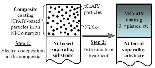
Figure 1 - Schematic illustration of the two-step process for synthesizing MCrAlY coatings
Similar to thermal spray processes such as APS, the electrolytic codeposition process is categorized as a low-cost coating process, due to the low capital investment involved. The process cost is mainly driven by the material and labor cost. If an automated electroplating line is installed with batch operation, labor cost can be significantly reduced. Even though the raw material cost may be similar for the two processes, the electro-codeposition process consumes much less energy than traditional thermal spray processes and has little material waste (no overspray),6 which can lead to a further reduction in the overall cost. In addition to the non-line-of-sight nature, the ability to produce homogeneous and dense coatings makes electro-codeposition a more attractive choice.
Compared to conventional electroplating, electro-codeposition is a more complicated process because of the particle involvement in metal deposition. It is generally believed that five consecutive steps are involved:14,15 (i) formation of charged particles due to ions and surfactants adsorbed on particle surface; (ii) physical transport of particles through a convection layer; (iii) diffusion through a hydrodynamic boundary layer; (iv) migration through an electrical double layer and finally, (v) adsorption at the cathode where the particles are entrapped within the metal deposit. The quality of the electro-codeposited coatings depends upon many interrelated parameters, including the type of electrolyte, current density, pH, concentration of particles in the plating solution (particle loading), particle characteristics (composition, surface charge, shape, size), hydrodynamics inside the electroplating cell, cathode (specimen) position, and post-deposition heat treatment, if necessary.14,15,19,20
There are several factors that can significantly affect the oxidation and corrosion performance of the electrodeposited MCrAlY coatings, including: (1) the volume percentage of the CrAlY powder in the as-deposited composite coating; (2) the CrAlY particle size/distribution and (3) the sulfur level introduced to the coating from the electroplating solution. The objective of this project is to investigate and optimize the electro-codeposition process to improve the MCrAlY coating oxidation/corrosion performance. In particular, the parameters to be examined are:
- Task 1 (Year 1) The effect of codeposition parameters on the CrAlY particle incorporation in the coating.
- Task 2 (Year 2) The effect of CrAlY particle size on the CrAlY particle incorporation.
- Task 3 (Year 3) The effect of the electroplating solution on the coating sulfur level.
Importance to NASF / AESF Foundation Research
This project examines some practical, yet very important aspects associated with the development of NiCo-CrAlY composite coatings using electrolytic codeposition. Instead of using a beaker setup (as in most laboratory R&D), a small rotating barrel is utilized, which not only allows us to coat the entire surface of samples with different geometries, but also offers the scale-up potential. The parameters identified in this study can be readily translated to the industrial-scale processes where similar coatings are produced. In the overall project, we will examine current density, CrAlY particle loading, and CrAlY particle size and elucidate their effects on the CrAlY particle incorporation in the composite coating. In addition, three electrolytes (Watts bath, all-chloride and fluoborate solutions) will be studied to compare the sulfur level in the resultant NiCo-CrAlY coatings.
While the fundamental aspects of this coating technique have been funded by other federal grants, they do not cover the practical aspects of increasing the particle incorporation and reducing the sulfur impurity in the deposit. Also, the findings from this study can be related to other coatings fabricated via electro-codeposition, which is a very versatile process for making composite coatings, in which particles of metals, ceramics and polymers can be codeposited. Since the applications of composite coatings are vast, there is considerable interest across fields in the electroplating community.
Technical approach
The Hull cell is widely used in the electroplating industry, as it positions the cathode at an angle relative to the anode and under DC conditions establishes a known range of current densities across the cathode surface. However, based on the recent study carried out by Faraday Technology,** the Hull cell has inadequate solution stirring to maintain the suspension of the powders within the electrolyte. As such, they quickly fall out of solution without incorporation into the coating. In this project, the rotating barrel will be used to study the effect of electro-codeposition parameters on the particle incorporation in the coating. This setup also offers two additional benefits: (i) it allows us to coat the entire surface of samples with different geometries and (ii) it has the scale-up potential.
Small disk or rod samples of Ni-based alloys or stainless steel (such as 304SS) were used as the substrates. For the aforementioned Tasks 1 and 2, involving the study of the CrAlY particle incorporation in the coating, a Watts Ni-Co plating solution containing CrAlY alloy powders (e.g., Cr-37 Al-1.7 Y, wt%) was used.
The NiCo-CrAlY composite coatings were characterized using optical microscopy and scanning electron microscopy (SEM) equipped with energy dispersive spectroscopy (EDS). To determine the volume fraction of the incorporated CrAlY particles, multiple backscattered-electron images were taken from different locations along the coating cross-section, which will be processed using the ImageJ software. The brightness and contrast of the images were adjusted by setting a proper threshold such that the particles could be separated from the background. The area fraction of the CrAlY particles determined by the image analysis was assumed to be equivalent to its volume fraction.
Results from the First Quarter
In the first quarter (since the project officially started on February 9, 2018), we focused
on the proposed research activities in Task 1, i.e., the effect of codeposition parameters on the CrAlY particle incorporation in the coating. In particular, work dealt with the preparation of the substrate specimens and powders needed in the electro-codeposition experiments. The properties of the four alloy powders (two atomized powders and two ball-milled powders) were characterized, including particle size distribution, morphology and density. Electro-codeposition experiments were carried out in the rotating barrel using ball-milled CrAlY and atomized CoNiCrAlY powders at a current density of 20 mA/cm2. The particle geometries not only affected the particle incorporation in the coating but also showed an effect on coating surface roughness.
Experimental Procedure
Sample and powder preparation.
Substrates were made from available nickel-based alloys including Ni 200 (>99.0 Ni, with 0.25 Cu-0.40 Fe-0.35 Mn-0.15 C-0.35 Si-0.01 S max.), René 80 (Ni-3.0 Al-14.1 Cr-9.7 Co-4.3 W-4.0 Mo-5.0 Ti-0.18 C (wt%), 130B-200 Zr-7 S in ppmw) and CMSX-4 (Ni-5.9 Al-6.3 Cr-9.6 Co-6.5 W-0.6 Mo-2.9 Re-6.5 Ta-1.0 Ti (wt%), 1100 Hf-17 C-1 S in ppmw). Disc specimens (1.6 mm thick, ~17 mm in diameter) were cut using an abrasive cutting saw. The specimens were ground to #600 grit using SiC grinding paper, followed by grit-blasting with #220 Al2O3 grit and ultrasonic cleaning in hot water and acetone.
Four pre-alloyed powders were used in this experiment, including two commercial powders (purchased from PSI and Sandvik) and two laboratory powders made at Tennessee Technological University (TTU); their chemical compositions are given in Table 1. The commercial powders were produced by gas atomization and sieving if necessary. For the TTU powders, a cast ingot was made via arc melting, which was crushed with a hammer and then ball-milled in a high-energy ball mill for 30-45 min. Subsequently, the powder was sieved through 325-mesh (44 μm) and 625-mesh (20 μm) screens. Particle analysis was carried out using a Malvern Mastersizer 2000 Laser diffractor. The density of the alloy powder was determined using a pycnometer (AccuPyc 1340).
Table 1 - Chemical compositions of alloy powders used in the electro-codeposition experiments.

Electro-codeposition
A rotating barrel system shown in Fig. 2 was used in the electro-codeposition experiments. The 185-mL barrel was constructed of a rigid polypropylene frame covered by a thin nylon membrane with ~1 μm mesh size. The nylon membrane allows the exchange of plating solution between the barrel and the tank but prohibits escaping of the particles. The barrel was attached to a gear set driven by a variable speed DC motor. The barrel and gear set were then suspended in a 5-L tank of Watts nickel plating solution such that the barrel was fully submerged. Specimens were placed longitudinally inside the barrel and centered on the barrel’s axis of rotation. To connect the specimen to the power supply, a flexible metal wire covered with Teflon tubing was attached to the sample. A solid nickel anode was placed outside of the barrel along with a mechanical stirrer and heating coil. The specimens were plated at a current density of 20 mA/cm2 for 2 h at 50°C with the pH of 3.7-3.9. The particle concentration in the bath was kept at 20 g/L and the barrel rotation speed at 7 RPM.
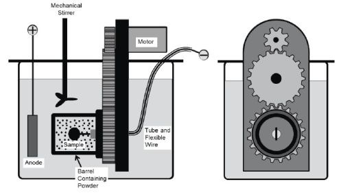
Figure 2 - Schematic of the barrel system used in the electro-codeposition process.
Coating characterization
The as-deposited coatings were examined using scanning electron microscopy (SEM). Prior to metallographic sample preparation, the specimens were copper-plated. To determine the quantity of particles incorporated in the coating, multiple backscattered-electron images were taken at different locations along the coating cross-section, which were then processed using ImageJ software.
Results and discussion
Particle analysis
Figure 3 shows the particle analysis results for the three powders, i.e., ball-milled CrAlY (TTU), atomized CoNiCrAlY (PSI) and atomized CrAlY (Sandvik). The ball-milled CrAlYTa (TTU) powder had a particle size distribution similar to that of the ball-milled CrAlY (TTU) powder due to the same powder preparation procedure, which was not measured. Powder characteristics, including particle size, shape and density, are summarized in Table 2.
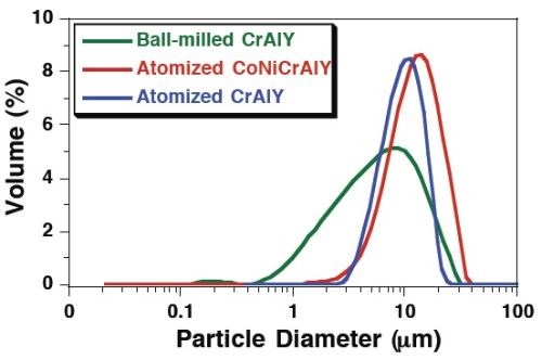
Figure 3 - Particle size distribution differential plots of ball-milled and atomized powders.
Table 2 - Powder characteristics.

Values of D10, D50 and D90 describe that 10%, 50%, and 90% of the particles (based on volume) have a particle size smaller than the value given. TTU ball-milled powder had a D50 value smaller than those of commercial atomized powders (5.6 vs. 10-12 μm). The density of CrAlYTa powder (5.5 g/cm3) was slightly higher than the baseline CrAlY powder (4.5 g/cm3) due to the tantalum addition, and the CoNiCrAlY had an even higher density (7.8 g/cm3) with additional cobalt and nickel. The ball-milled powder also exhibits an irregular shape, in contrast to the spherical shape of the gas-atomized powder. It is worth pointing out that the CoNiCrAlY powder (with cobalt and nickel) does not have the desired chemical composition for making the MCrAlY coatings; it was included in the experiments in order to understand the effect of powder density on the particle incorporation in the electro-codeposited coatings.
Electro-codeposition
Figures 4 and 5 present the microstructures of the electro-codeposited coatings using two different powders (ball-milled CrAlY and atomized CoNiCrAlY). Again, the different shapes of the particles can be clearly seen from both the surface and cross-section of the as-coated specimens. The atomized particles were mostly spherical, while the ball-milled CrAlY powders were asymmetric. Further observation of the surface showed growth of the nickel deposit on the particles, in addition to the nickel matrix, as these particles are conductive. It appears that the geometries of the particles could also lead to the different surface roughness observed on the coated specimens. Additionally, based on the image analysis results, the particle incorporation for CoNiCrAlY powder was significantly greater than the CrAlY powder, 46 vs. 30 vol%.
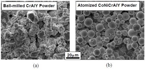
Figure 4 - SEM surface images of the coatings with (a) ball-milled CrAlY and (b) atomized CoNiCrAlY powders.
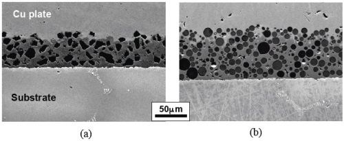
Figure 5 - SEM cross-sectional images of the coatings with (a) ball-milled CrAlY and (b) atomized CoNiCrAlY powders.
Future work
In the next quarter, additional current density levels (5-15 and 40-60 mA/cm2) will be employed in the electro-codeposition process to complete the study of the effect of current density on coating particle incorporation.
References
1. G.W. Goward, Surf. Coat. Technol., 108-109, 73-79 (1998).
2. J.H. Wood and E.H. Goldman, Superalloys II, C.T. Sims, N.S. Stoloff, and W.C. Hagel, Eds., Wiley, Hoboken, NJ, 1987; p. 359.
3. J.R. Nicholls, MRS Bulletin, 28 (9), 659-670 (2003).
4. D.P. Whittle and J. Stringer, Phil. Trans. Royal Soc. London A, 295 (1413), 309-329 (1980).
5. B.A. Pint, Proc. John Stringer Symposium, P.F. Tortorelli and P.Y. Hou. Eds., ASM Int’l., Materials Park, OH, 2003; p. 9.
6. A. Feuerstein, et al., J. Therm. Spray Technol., 17 (2), 199-213 (2008).
7. R.S. Lima and B.R. Marple, J. Therm. Spray Technol., 16 (1), 40-63 (2007).
8. R. Mévrel, Mater. Sci. Eng. A, 120-121 (1), 13-24 (1989).
9. J. Foster, B.P. Cameron and J.A. Carew, Trans. Inst. Met. Finish., 63 (3-4), 115-119 (1985).
10. F.J. Honey, E.C. Kedward and V. Wride, J. Vac. Sci. Technol. A, 4 (6), 2593-2597 (1986).
11. X. Lu, R. Zhu and Y. He, Oxid. Met., 43 (3-4), 353-362 (1995).
12. M-P. Bacos, et al., Surf. Coat. Technol., 162 (2-3), 248-260 (2003).
13. Y. Zhang, JOM, 67 (11), 2599-2607 (2015).
14. C.T.J. Low, R.G.A. Wills and F.C. Walsh, Surf. Coat. Technol., 201 (1-2), 371-383 (2006).
15. F.C. Walsh and C. Ponce de Leon, Trans. Inst. Metal Fin., 92 (2), 83-98 (2014).
16. C.B. Wang, et al., Wear, 253 (5-6), 563-571 (2002).
17. I. Garcia, J. Fransaer and J.P. Celis, Surf. Coat. Technol., 148 (203), 171-178 (2001).
18. A. Hovestad, R.J.C.H.L. Heesen and L.J.J. Janssen, J. Appl. Electrochem., 29 (3), 331-338 (1999).
19. J.R. Roos, et al., JOM, 42 (11), 60-63 (1990).
20. M. Musiani, Electrochim. Acta, 45 (20), 3397-3402 (2000).
About the author

Dr. Ying Zhang is Professor of Mechanical Engineering at Tennessee Technological University, in Cookeville, Tennessee. She holds a B.S. in Physical Metallurgy from Yanshan University (China)(1990), an M.S. in Materials Science and Engineering from Shanghai University (China)(1993) and a Ph.D. in Materials Science and Engineering from the University of Tennessee (Knoxville)(1998). Her research interests are related to high-temperature protective coatings for gas turbine engine applications; materials synthesis via chemical vapor deposition, pack cementation and electrodeposition, and high-temperature oxidation and corrosion. She is the author of numerous papers in materials science and has mentored several Graduate and Post-Graduate scholars.
Jason C. Whitman is a Ph.D. student in the Department of Mechanical Engineering, Tennessee Technological University, in Cookeville, Tennessee. His primary work is involved with the AESF Foundation Research Project R-119, Electro-codeposition of MCrAlY Coatings for Advanced Gas Turbine Applications.
*Corresponding author:
Dr. Ying Zhang, Professor
Department of Mechanical Engineering
Tennessee Technological University
Cookeville, TN 38505-0001
Tel: (931) 372-3265
Fax: (931) 372-6340
Email: yzhang@tntech.edu
** Faraday Technology, Inc., 315 Huls Drive, Englewood, OH 45315.
Related Content
Nanotechnology Start-up Develops Gold Plating Replacement
Ag-Nano System LLC introduces a new method of electroplating based on golden silver nanoparticles aimed at replacing gold plating used in electrical circuits.
Read MoreAdvantages to Pumped Eductor Agitation
Not all agitation methods are created equally. Pumped agitation with eductor nozzles can improve process tanks and quickly show a reduction in operating costs while keeping staff safe, following environmental legislation and preventing pollution.
Read More3 Tests to Ensure Parts are Clean Prior to Plating
Making sure that all of the pre-processing fluids are removed prior to plating is not as simple as it seems. Rich Held of Haviland Products outlines three tests that can help verify that your parts are clean.
Read MoreHow to Choose Between Sulfate and Chloride-Based Trivalent Chromium
There are several factors to consider when choosing between sulfate and chloride-based baths for trivalent chromium plating. Mark Schario of Columbia Chemical discusses the differences and what platers should keep in mind when evaluating options.
Read MoreRead Next
Education Bringing Cleaning to Machining
Debuting new speakers and cleaning technology content during this half-day workshop co-located with IMTS 2024.
Read MoreEpisode 45: An Interview with Chandler Mancuso, MacDermid Envio Solutions
Chandler Mancuso, technical director with MacDermid Envio discusses updating your wastewater treatment system and implementing materials recycling solutions to increase efficiencies, control costs and reduce environmental impact.
Read MoreMasking Solutions for Medical Applications
According to Custom Fabricating and Supplies, a cleanroom is ideal for converting, die cutting, laminating, slitting, packaging and assembly of medical-grade products.
Read More


