History of Chromium Plating
A review article originally printed as Plating & Surface Finishing, 71 (6), 84-91 (1984) on the occasion of the 75th anniversary of the founding of the American Electroplaters Society.
A review article originally printed as Plating & Surface Finishing, 71 (6), 84-91 (1984) on the occasion of the 75th anniversary of the founding of the American Electroplaters Society.
Recollections of the early days, business transactions, the development of trivalent solutions and thin deposits are among the highlights of this historical account.

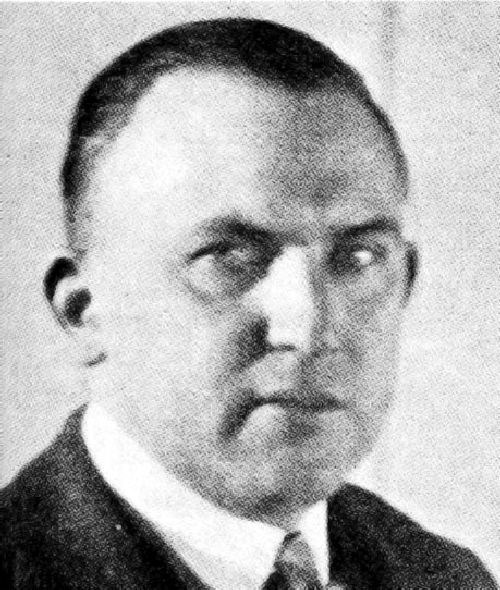
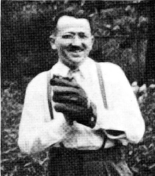
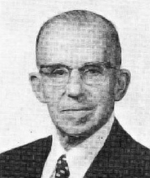
Figure 1 - George J. Sargent (1885-1965) about 1920.
At the time of the founding of the AES in 1909, George J. Sargent (Fig. 1), a pioneer of chromium deposition, earned his M.A. degree at New Hampshire University and continued graduate study at Cornell University until 1914.1,2 From 1911 to 1914 he worked on chromium deposition under Bancroft, trying to produce a 10-lb. batch of electrolytic chromium in a single continuous run. This he failed to do, but he did receive the Ph.D. degree in 1912 for his chromium work up to that point. The publication of his paper in 1920 and that of Schwartz in 1923 attracted considerable attention (including that of the writer), and led to the development of a commercial process by Fink and Eldridge by May 1924 at Columbia University.2
Fink and Eldridge were able to attract good financial backing from John T. Pratt Sr. through a connection at the Metropolitan Museum of Art. The Chemical Treatment Company was formed and established a job shop for chromium plating on Center Street in New York by late 1924. This job shop was competitive with another founded by Schwartz and his associates in Jersey City, NJ - The Chromium Products Corporation. It had the backing of the Metal & Thermit Corporation and was under a German patent to Grube.
Figure 2 - Half of a large electrotype chromium plated by the Chemical Treatment Co. in 1926 and tested on a long run [From High D. McLeese (1899-1980)].
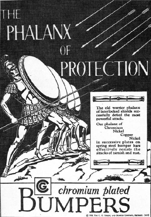
The two original companies, the Chemical Treatment Company and the Chromium Products Corporation, a subsidiary of Metal and Thermit Corporation, plated many sample jobs and advertised their processes energetically from June 1925 through 1926 (Fig. 2). Almost overnight, "chromium plated" became a byword for a pleasing, bright, non-tarnishing finish of great durability.
The merger of the first two companies as "the first step in the simplification of the patent situation"3 was announced July 22, 1926.4 By that time the Chemical Treatment Company was operating an additional plant in Waterbury, CT.5 The new corporation was called the Chromium Corporation of America, and operated a number of job shops in large cities until recently.
The advertising and other overhead costs grew so great without promise of rapid return on the investment that Mr. Pratt decided to withdraw from active management in December 1926 and gave an elaborate farewell dinner at the Metropolitan Club of New York on Fifth Avenue that was long remembered by participants. Unfortunately, Mr. Pratt died June 17, 1927.6 He was an excellent sponsor to the infant industry of chromium plating.
Mr. Eldridge left a few months later to go with a new firm, the General Chromium Corporation in Detroit. This firm was based mainly upon [Marvin] Udy's patent applications owned by the Electro-metallurgical Company of Union Carbide. Other interests such as the Vacuum Can Company of Chicago and Fred J. Fisher of Detroit7 were also included.
As soon as the Fink Patent issued April 20, 1926, Udy copied Fink's claims on his applications, thus forcing the patent office to declare an interference. After July 1926, the Fink patent was owned by the Chromium Corporation of America. In order to dissolve the interferences, the General Chromium Corporation and the Chromium Corporation of America formed a new company, United Chromium, Incorporated,8 in September 1927. The patent counsel of both firms deliberated at great length and finally decided that Udy should sign concessions of priority to Fink in both interferences in February 1928.
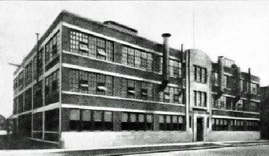
Figure 3 - Offices, labs and plant of the General Chromium Corp. and the Udylite Process Co. in Detroit, 1927.
.jpg;maxWidth=600)
Figure 4 - Hale-Udy composite bus bar resting on top of chromium tank, as published by Udy.11
A great deal of work was done with this assemblage, but in Udy's final report dated November 22, 1929, his results were tabulated in the form of the current density produced at 45°C with a given voltage and electrode spacing. His conclusion was in part, "Voltage operation is very convenient and, after experience has been obtained, it can be used almost entirely. By this I mean that if you have a definite known electrode spacing and apply a constant voltage, the current density will be constant."
Udy's employment with Electrometallurgical Company was terminated in 1931, and he did not return to plating work. Phil Hale filed a patent on the composite bus bar January 7, 1932.12 A successor, Clarence H. Peger calls it the "Reversible Rack 2 Bus Bar System" and makes a good contribution to chromium plating technology based upon its use.
Chromic acid, 15 g/L
Potassium hydroxide, 60 g/L
Chromium oxalate, 180 g/L
Chromic acid was found to be beneficial to this oxalate solution, but more than about 10-20 g/L tended to oxidize the oxalate radical. It becomes something of a moot question whether this is a trivalent or a dilute hexavalent solution. The good color of the deposits obtained tends to favor the concept of deposition from the small amount of chromic acid present.
Webersinn no doubt got a good deal of his inspiration from the publications of Mazzucchelli,24,25 who found that ammonium chromium oxalate, Cr(C2O4NH4)3∙H2O gave a much better solution than any other trivalent salt. However, he did not get as good results as those obtained in the commercially used hexavalent solutions in Italy. Nevertheless, Mazzucchelli prepared his crystalline ammonium chromium oxalate by pouring 2 molar chromic acid solution into 6 molar oxalic acid and heating until crystallization occurred. He used a two-compartment cell, but frequently found Cr+6 in the catholyte.
At the same time, Britton and Westcott found better results with oxalate than with acetate or tartrate.26 Charles Kasper of the Bureau of Standards published an outstanding review in 1933 on deposition from both chromic and chromous solutions.27 The writer's reviews in 1963 and 1974 give some references to the use of chromium ammonium oxalate in brush plating.16,17
S. Eguchi in Japan has also, to some extent, confirmed Webersinn's work with oxalate, but again the distinction between hexavalent and trivalent solutions tends to become blurred or lost and quantitative investigation increasingly difficult.28-32 The language barrier is enough of a problem, but for some unaccountable reason, Chemical Abstracts will not refer to the Journal of the Metal Finishing Society of Japan as such, but insists on calling it Kinzoku Hyomen Gijutsu - a constant handicap. Eguchi typically may use 200 g/L chromic acid solution to which he adds 75 g/L (NH4)2SO4 and 500 g/L oxalic acid (H2C2O4∙2H2O) and lets this mixture stand overnight at room temperature to get a solution with a major part of the chromic acid converted to trivalent chromium, but about 24 to 76 g/L of chromic acid remaining.32
A brief paper in 1938 cast the shadow of some things to come. Wade and Yntema33 found best results from a solution of 0.5M chromic sulfate containing 4 moles of ammonium sulfate and 0.1 mole/L of ammonium oxalate. Citric acid also had beneficial effects. Organic acids and ammonium sulfate raised the pH at which basic chromium salts precipitated, and thus widened the plating range.
The U.S. Bureau of Mines began a long-range investigation of the electrowinning of chromium metal in 1939, primarily to utilize low-grade domestic chromium ore, but also to study the properties of high-purity chromium metal. This investigation has already been referenced in the last three editions of Modern Electroplating.15-17 At the same time, approximately, the Electro Metallurgical Company division of Union Carbide Corporation made a detailed study of the methods and procedures developed by the Bureau of Mines and added what appeared to be the best of them to its own conceptions and developments. The confluence of these two powerful streams of investigation broke down many stubborn obstacles and was rewarded with the creation of an outstandingly fortunate and successful development.
A report34 on the electrolysis of chromic sulfate solutions cited an efficiency of 45 percent for the reduction of Cr+3 and was followed by pilot-plant operations claiming an efficiency of 60 percent.35 Electrolyte modifications and improved cell design were discussed in a third report.36 Subsequent papers37-40 addressed developments leading to a commercial plant designed to produce up to 6 million lb./year of chromium. It went on stream in 1954 with an average plant efficiency of 45 percent. Good descriptions of this were given by F.E. Bacon.41-43 Electrodeposition of chromium from trivalent solutions was also reported in Japan44-49 and Russia.50
Jangg and Burger51 studied chromium deposition on mercury cathodes, and obtained as high as 68 percent efficiency from a 6 g/L solution of Cr+3 sulfate containing 50 g/L ammonium sulfate at 30°C by raising the pH to 3.2. With 4.0 g/L chromium as Cr+3 chloride at 30°C and pH 1.5, they obtained 70 percent current efficiency at the higher current densities. The importance of black, spongy deposits of low overvoltage in their work is discussed elsewhere.52
In 1969, Bharucha and Ward of the British Non-Ferrous Metals Research Association (BNFMRA) published information on a trivalent chromium plating process using an unusual solution with 50 percent by volume dimethylformamide (DMF) as the solvent for chromic chloride.53 The research was also sponsored by the International Lead Zinc Research Organization (ILZRO), New York, NY, and the results were patented.54 The remarkable feature was that efficiencies in the range of 40 to 50 percent were obtained. These efficiencies were confirmed in two articles published in 1971.55,56 The second article is particularly helpful, and discloses that some Cr+3 is reduced to Cr+2, which remains in the solution until re-oxidized and is not further reduced to metal. This creates a reducing condition in the solution that makes metal contamination much less of a problem. The final concentration of DMF selected was 400 g/L, or about 40 percent by volume.
The BNFMRA made an agreement with Albright and Wilson Ltd. in 1970 for the joint development and commercial exploitation of the DMF process.57 Difficulties and production experiences do not seem to have been publicized. Outdoor corrosion tests were reported in 1973 in which directly plated zinc-die-cast parts failed by dulling more rapidly than the same parts plated with conventional Cr+6 baths.58 On the other hand, much later tests in 1977 with both chloride and sulfate DMF baths gave better results in obtaining inclusions of Al2O3 and Cr3C2 particles in the Cr+3 deposits than in deposits from Cr+6 baths.59
J.E. Bride was employed at Battelle Memorial Institute from 1948-56 and did some work on Cr+3 plating in this period. Then from 1956-72 he worked at Diamond Alkali Company, later Diamond Shamrock Corporation, the latter part of this period being devoted to developments in Cr+3 plating. In 1972 he went with E. I. du Pont de Nemours & Company, Inc., and it took over the dossier of patents he had developed with some collaborators and added them to some of its own.60-74
At the end of 1972 he published a comprehensive article.75 DuPont offered these patented procedures to the trade but it is not clear just what they may have contributed to Cr+3 technology. Presumably they became part of the effort of Albright and Wilson Ltd. to establish the process, perhaps with formate or glycollate as a complexing agent for Cr+3.
In mid-1975 and 1976 a new process, Alecra 3, was introduced, and in the process of doing this, Crowther and Renton76 and Chalkley, Crowther and Renton77 published some discussion of past failures and problems. There was burning at high current densities, and inability to plate into recessed areas. The coverage at low current densities was unacceptable, and compared unfavorably with that of existing hexavalent electrolytes. After a limited time the formation of a little hexavalent chromium caused the plating speed to fall off slowly to zero, and the solution could not be restored by sulfur dioxide treatment. In a later process78 it was found possible to reduce hexavalent chromium to Cr+3 by adding hydrogen peroxide and removing excess peroxide by heating. This, of course, would oxidize any Cr+2 present. The same would probably also be true of any hypophosphite present, the use of which was mentioned in several patents.79-80 It appears that ferrocyanide was added to these baths to remove trace metal contaminants.81 An important patent basic to this process should also be listed.82 It covers the use of formate or acetate together with a bromide and other useful constituents.
The Harshaw Chemical Company entered into an agreement with Albright & Wilson Ltd. in 1976 to distribute the new process in North America.83 The process is also sold by Waldberg SA in France. No doubt there are many other international sales arrangements.
The properties of trivalent chromium deposits are distinctly different from those from Cr+6 solutions. They generally have a darker color due to impurities and resemble the appearance of stainless steel. The deposits are intensely microporous with more than 1 million pores per cm2.78 At thicknesses of more than 2.5 μm (0.0001 in.) they become dull, and over 15 μm (0.0006 in.) powdery. The structure is weak and friable, and somewhat lacking in adhesion in greater thicknesses, and is consequently not considered for wear resistance.
While there is better coverage around holes and on underneath surfaces in practice, many recesses were more difficult to cover than expected, and doubts were raised as to the validity of Hull Cell work.76-77 However, the charts that were frequently drawn of plating rate vs. current density contained an element of sophistry and were a little misleading. Thus the plating rate could not remain constant while the current density increased unless there was a substantial decrease in current efficiency at the same time. The writer published some current efficiency/ current density curves from Huba and Bride's patent67 to show the lack of reproducibility of supposedly identical solutions, presumably due to impurities.
This difference was shown by Roubal,84 indicating the failure of chromium to deposit at a lower current density from Cr+3 solutions than from Cr+6. Again, Moritz indicates plating to a lower current density with Cr+6 than with Cr+3 by means of a current efficiency/current density chart.85
A further paper by Barnes, Ward and Carter86 reports good results for even thin deposits of decorative trivalent chromium plate for outdoor corrosion resistance directly on zinc. If the very small pores in trivalent chromium plate are plugged with dried and insoluble corrosion products the performance is good. On the other hand, in accelerated tests with continuous wetting with a highly conducting electrolyte, corrosion may continue unchecked and cause undercutting of the chromium.
Another report on corrosion characteristics was published by Snyder.87 Gianelos contributed three reviews of recent experience.88-90
Roubal84 reported a careful investigation of the Gyllenspetz and Renton patent.82 This was extended by throwing-power measurements with the now-old-fashioned Haring-Blum cell. An extensive study of trivalent chromium publications was reported by J. Datta91 from a dissertation submitted to TH-Aachen in Germany. Unfortunately, a more detailed publication has not appeared. A preliminary report is given on a citrate bath developed by Datta.
Schloetter obtained an early patent92 in which he added ammonium thiocyanate to chromic chloride baths. He thought chromium anodes could be used and dissolved directly in the form of chromic salt, but in the writer's experience this never occurs and chromium anodes only dissolve directly as chromic acid. Levy and Mornyer93-94 also used thiocyanate to get better chromium deposition from trivalent baths.
Another new Cr+3 process was developed in England by IBM United Kingdom Laboratories Ltd. and is being sold by W. Canning Materials Ltd. It has a base of thiocyanate complexant and a number of patents have been obtained. A two-compartment cell is used; two articles95-96 describe the working and advantages.
Still another new process is described by Tomaszewski and Fischer of Udylite.97 Professor Tajima remarked in the discussion that Cr+3 is not as corrosion resistant as Cr+6 and is grayer in color. The Toyota Company set up a pilot plant for the trivalent system but did not adopt it for production. Trivalent chromium is not now in use in Japan on either automobiles or cameras.98
In 1948 Morisset published a little-known paperback book of 220 pages reviewing industrial applications of hard chromium. In 1952, he published an excellent general textbook of 477 pages on chromium plating. This was translated into English and supplemented by Oswald, Draper and Pinner to make a 611-page book that appeared in 1954. This latter book became something of a "bible" that can be found in the hands of many older chromium platers, but is otherwise not very well known. It is said to have been translated into Russian and Japanese, but, unfortunately, the English edition went out of print in a few years.
Morisset published a handsome, 895-page, bound book, Chromage dur et decoratif, in 1961, but again it was not translated into English. Thus, by a sequence of events, we lack a high-grade, well-documented, comprehensive text of chromium plating technology in English. The second edition of the German book by Weiner in 1974 appeared in English translation by A. Walmsley in 1980, but this is a somewhat modest, albeit well-organized, text of 224 pages.
The only other text with a good bibliographical background is the eighth edition of Gmelin's Handbook of Inorganic Chemistry (in German, with English notes), System No. 52, "Chromium," Part A, Section 2, p. 473-622 (1963). This gives numerous references on specific subjects but is already 20 years out of date [in 1984 - Ed.]. It seems the only possibility of a good, up-to-date reference text on chromium deposition in English would be a multi-author effort of some kind.
Chromium-plated tin cans
If we go into a supermarket today and examine the tops of tin cans, we find that they fall into two classes - those with the bright, white metallic appearance of reflowed tin plate, and those with a clean, bluish, steely look. The two finishes are used interchangeably, sometimes on parts of a can, sometimes on complete cans. The amount of each finish is about half of the total number of cans. The cans that give the appearance of clean, bare steel are chromium plated by special procedures.
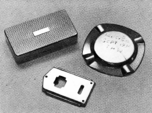
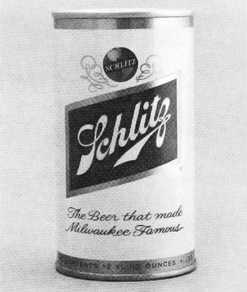
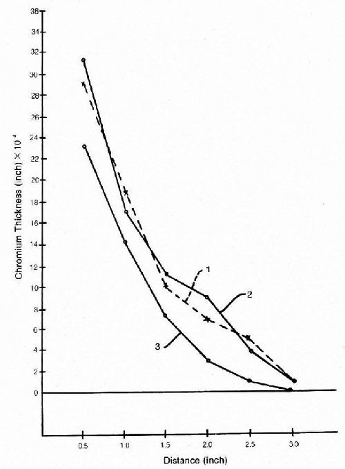
This is a revolution in can-making that was started in Japan about 20 years ago by H. Uchida and co-workers at the Fuji Iron and Steel Company Ltd. under the name Cansuper.99,100 The process was promptly adopted by American can makers, and beverage cans made in this manner were introduced on a large scale in 1967. A review was given elsewhere.17 The product has been dubbed tin-free steel (TFS) in view of its major function of replacing the scarce and expensive metal tin (Fig. 10). The chromium coating is extremely thin, less than 0.000002 in., or 0.05 μm, and is applied to the rapidly moving steel strip in a few seconds or even fractions of a second. It serves to promote adhesion of the coating of baked lacquer that follows, and to prevent filiform or underfilm rusting.
We have here an example where a thin coating is better than a thick coating. This is beyond the ken of practically all platers, who spend their lives being told to "put on a thicker coating." A μm is about 10,000 Angstroms (0.000040 in.), and if we take one-tenth of this, or 1000 Angstroms, as an upper coating thickness, we are dealing in coatings about 300 or 400 atoms thick at the most. Films thinner than this can be called "thin films" and are common in electronic work. Our contact with electronic work has to do with "thick films" such as plating through-holes of printed circuits, mostly for contact purposes. Since electroplating by its very nature has to start with thin films only a few atoms thick, it is an ideal way to produce thin films of all sorts that have properties different from those of bulk material. It might pay to study books such as those of Chopra.101,102 On page 266 of the recent book for example, we learn that extremely thin films of indium or tool steel have a lower coefficient of friction than ordinary thicknesses.
Chromium unpopular?
It has been said that beauty is in the eye of the beholder, but when automotive designers ask the public to gasp in admiration over black bumpers on a black car, we suspect the presence of quite a few individuals with tongue in cheek. A good technical review of the current situation was given by Pegram under the title "Bright Chrome Is Dead - Long Live Bright Chrome!"105 After discussing such subjects as alternative finishes, the genuine alternative, the genuine article, and nickel is so expensive, Pegram concludes: "Re-birth or no re-birth, long live bright chrome!"
When nickel plating was introduced in 1869-70, good quality was maintained on the whole, and it quickly had a surge of popularity bringing with it the introduction of dc generators around 1875-76 to displace batteries as the source of power. When the New York, Chicago and St. Louis Railway was built in 1881-82 from Buffalo to Cleveland, Chicago and St. Louis, it became known as the The Nickel Plate Road in the Cleveland and especially the Sandusky, Ohio, area. An account of many of the 32 ways that were suggested as the source of this name in a history of the railroad106 gave as the best one that "the company had the cash on hand to pay as the road was built, the term being borrowed from the barkeepers' slang, that the fellow who paid for his drinks on delivery and never had his score chalked, was a nickel-plated fellow."
The early popularity of "chromium plated" as synonymous with "durable, long-lasting, untarnishable" and so on was mentioned in discussion of the early days. More recently, an author discussing restored antique automobiles called them "Chrome Dreams,"107 and a 1980 account108 of General Motors as the equivalent of the 14th largest nation in the world is called "Chrome Colossus." One cannot consider the adjective "chrome" as anything but a flattering one.
1. G. Dubpernell, Plating, 59, 638 (1972).
2. G. Dubpernell, Plating, 47, 35 (1960).
3. Metal Industry, (NY) 24, 332 (1926).
4. Automotive Industries, 55, 155 (July 22, 1926).
5. Metal Industry, (NY) 24, 349 (1926).
6. Metal Industry, (NY) 25, 309 (1927); Brass World, 23, 248 (1927).
7. Metal Industry, (NY) 25, 267 (1927); Brass World, 23, 211 (1927).
8. Metal Industry, (NY) 25, 25 (Sept. 1927); Brass World, 23, 7 (Sept. 1927).
9. Metal Industry, (NY) 27, 57 (Jan. 1929)
10. Metal Industry, (NY) 27, 250 (May, 1929); Brass World, 25, 156 (June 1929).
11. M.J. Udy, Metal Progress, 21, 23 (June 1932).
12. P.P. Hale, U.S. Patent 1,963,363 (1934).
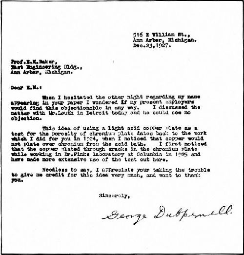
13. E.M. Baker and W.L. Pinner, SAE Journal, 22, 331 (1928).
14. G. Dubpernell, Trans. Electrochem. Soc., 80, 607 (1941); Modern Electroplating (special volume, ECS) p. 135 (1942).
15. A.G. Gray, ed., Modern Electroplating, John Wiley & Sons, Inc., New York, NY, 1953; p. 159.
16. F.A. Lowenheim, ed., Modern Electroplatng, 2nd ed., John Wiley & Sons, Inc., New York, NY, 1963; p. 110.
17. F.A. Lowenheim, ed., Modern Electroplating, 3rd ed., John Wiley & Sons. Inc., New York, NY, 1974; p. 115.
18. J.W. Manquen, Plating & Surface Finishing, 66, 47 (1979).
19. E.M. Baker, U.S. Patent 1,504,206 (1924).
20. J.F.K. McCullough and B.W. Gilchrist, U.S. Patent 1,781,789 (1930).
21. J.F.K. McCullough and B.W. Gilchrist, U.S. Patent 1,797,357 (1931).
22. J.F.K. McCullough and B.W. Gilchrist, U.S. Patent 1,838,777 (1931).
23. J.F.K. McCullough, U.S. Patent 1,863,868 (1932).
24. A. Mazzucchelli, Memorie R. Accad. Italia, Classe die Chemica, 2, 1, 5-15 (1931).
25. A. Mazzucchelli, Gazz. Chim. Ital., 62, 7, 756, 764 (1932).
26. H.T.S. Britton and O.B. Westcott. Trans. Far. Soc., 28, 627 (1932); J. Electrodepositor's Tech. Soc., 8, p. 5-1 to 5-9 (1933).
27. C. Kasper, Bureau of Standards J. Research, 11, 515 (1933).
28. S. Eguchi, J. Metal Fin. Soc. Japan, 19, 11, 451 (1968); see C.A. 70, 63376 (1969); French translation Bull., Documentation Centre D'lnformation du Chrome Dur, p. 1-12 (December 1969).
29. S. Eguchi, Japanese Patent 71-40, 761 (1971); see C.A. 77, 159566 (1972).
30. S. Eguchi, et al., J. Metal Fin. Soc. Japan, 33, 3,109 (1982). see C.A. 97, 81681 (1982)
31 S. Eguchi, et al., J. Metal Fin. Soc. Japan, 33, 4,136 (1982); see C.A. 97, 81682 (1982).
32. S. Eguchi, et al., J. Metal Fin. Soc. Japan, 33, 6,272 (1982); see C.A. 97, 190308 (1982).
33. W.H Wade and L.F. Yntema, Trans. Electrochem. Soc., 74, 461 (1938).
34. R.R. Lloyd, W.T. Rawles and R.G. Feeney, Trans. Electrochem. Soc., 89, 443 (1946).
35. R.R. Lloyd, J.B. Rosenbaum, V.E. Homme and L.P. Davis, Trans. Electrochem. Soc., 94, 122 (1948).
36. R.R. Lloyd, J.B. Rosenbaum, V.E. Homme, L.P. Davis and C.C. Merrill, J. Electrochem. Soc., 97, 7, 227 (1950).
37. Steel, 127, 92 (December 4, 1950).
38. J.B. Rosenbaum, R.R Lloyd and C.C. Merrill, Electrowinning Chromium Metal, U.S. Bureau of Mines, Report of Investigations 5322, 58 pages (March 1957).
39. R.R. Lloyd in Chromium, Vol. II, M.J. Udy, ed., Reinhold Publishing Corp., New York, NY, 1956; p. 51.
40. M.C. Carosella and J.D. Mettler in Ductile Chromium, proc. of a conference published by ASM, Cleveland, OH, 1957; p. 75.
41. F.E. Bacon in Encyclopedia of Electrochemistry, C.A. Hampel, ed., Reinhold Publishing Corp., New York, NY, 1964; p. 198.
42. F.E. Bacon in Encyclopedia of Chemical Process Equipment, W.J. Mead, ed., Reinhold Publishing Corp., New York, NY, 1964; p. 99.
43. F.E. Bacon in Kirk-Othmer Encyclopedia of Chemical Technology, 2nd ed., Vol. 5, Wiley-lnterscience, New York, NY, 1964; p. 451.
44. T. Yoshida and R. Yoshida, J. Chem. Soc. Japan, Ind. Chem. Section, 58, 89 (1955); See C.A. 49, 14540 (1955).
45. T. Yoshida, U.S. Patent application, ser. no. 182, 410 (1950).
46. T. Yoshida, U.S. Patent 2,704,273 (1955).
47. T. Yoshida, U.S. Patent 2,766,196 (1956).
48 T. Yoshida, U.S. Patent 2,988,492 (1961).
49. "Denki Kagaku" (electrochemistry) News Letter, 1, 4, 9 (1967).
50. V.V. Stender, ed., Electrometallurgy of Chloride Solutions, Plenum Publishing Corp., New York, NY, 1965; p. 87.
51. G. Jangg and E. Burger, Electrochemica Acta, 17, 1883 (1972).
52. G. Dubpernell, Plating and Surface Finishing, 62, 574 (1975).
53. N.R. Bharucha and J.J.B. Ward, Products Finishing, 33, 64 (January 1969).
54. N.R. Bharucha and J.J.B. Ward, British Patent 1,144,913 (1969).
55. J.J.B. Ward, I.R.A. Christie and V.E. Carter, Trans. Institute of Metal Finishing, 49, 3, 97 (1971).
56. J.J.B. Ward and I.R.A. Christie, Trans. Institute of Metal Finishing, 49, 4, 148 (1971).
57. Electroplating, 23, 5, 59 (1970).
58. V.E. Carter and I.R.A. Christie, Trans. Institute of Metal Finishing, 51, 2, 41 (1973).
59. C.A. Addison and E.G. Kedward, Trans. Institute of Metal Finishing, 55, 2, 41 (1977).
60. A.J. Deyrup, U.S. Patent 3,006,823 (1961).
61. T. Berzins, U.S. Patent 3,021,267 (1962).
62. J.E. Bride, U.S. Patent 3,706,636 (1972).
63. J.E. Bride, U.S. Patent 3,706.637 (1972).
64. J.E. Bride. U.S. Patent 3.706,638 (1972).
65. J.E. Bride and F. Huba, U.S. Patent 3,706,639 (1972).
66. J.R. Brannan, U.S. Patent 3,706,640 (1972).
67. F. Huba and J.E. Bride, U.S. Patent 3,706,641 (1972).
68. J.R. Brannan, U.S. Patent 3,706,642 (1972).
69. F. Huba, U.S. Patent 3,706,643 (1972).
70. J.E. Bride, U.S. Patent 3,725,214 (1973).
71. J.E. Bride, U.S. Patent 3,729,392 (1973).
72. J.E. Bride, U.S. Patent 3,732,270 (1973).
73. J.E. Bride, U.S. Patent 3,733,346 (1973).
74. J.E. Bride, U.S. Patent 3,733,347 (1973).
75. J.E. Bride, Plating, 59, 11, 1027 (1972).
76. J.C. Crowther and S. Renton, Electroplating and Metal Finishing, 28, 5, p. 6 (1975).
77. B. Chalkley, J.C. Crowther and S. Renton, paper presented at AES meeting in Denver, CO, June 30, 1976.
78. C. Barnes, J.J.B. Ward and J.R. House, Trans. Institute of Metal Finishing, 55, 2, 73 (1977).
79. J.T. Jordan, J.J.B. Ward and C. Barnes, U.S. Patent 3,917,517(1975).
80. J.J.B. Ward and C. Barnes, U.S. Patent 4,157,945 (1979).
81. J.C. Crowther and S. Renton, U.S. Patent 4,038.160 (1977).
82. J. Gyllenspetz and S. Renton, U.S. Patent 3,954,574 (1976).
83. Products Finishing, 41, 17 (October 1976).
84. J. Roubal, Galvanotechnik, 69, 4, 301 (1978).
85. G. Moritz, Galvano Teknisk Tidskrift, 25, 3, 4 (1982).
86. C. Barnes, J.J.B. Ward and V.E. Carter, Trans. Institute of Metal Finishing, 59, 1, 1 (1981).
87. D.L. Snyder, Plating and Surface Finishing, 66, 60 (June 1979).
88. L. Gianelos, Plating and Surface Finishing, 66, 56 (May 1979).
89. L. Gianelos, Products Finishing Directory, 1981, p. 104
90. L. Gianelos, Plating and Surface Finishing, 69, 30 (March 1982).
91. J. Datta, Galvanotechnik, 73, 2, 106 (1982).
92. M. Schloetter, U.S. Patent 2,088,615 (1937).
93. D.J. Levy and W.R, Momyer, Plating, 57, 11, 1125 (1970).
94. D.J. Levy and W.R. Momyer, J. Electrochem. Soc., 118, 10, 1563 (1971).
95. D.J. Barclay, N. Deeman, I.E. Such and J.M.L. Vigar, Proc. Interfinish 80, p. 79 (1980).
96. D. Smart, I.E. Such and S.J. Wake, Trans. Institute of Metal Finishing, 61, 3, 105 (1983).
97. T.W. Tomaszewski and R.E. Fischer, paper presented at AES Indianapolis Meeting, I-3 (1983).
98. S. Tajima, Metal Finishing, 81, 10, 96 (1983).
99. H. Uchida and O. Yanabu, U.S. Patent 3,113,845 (1963).
100. H. Uchida, O. Yanabu, A. Horiguchi and H. Sato, Trans. Institute of Metal Finishing, 42, 138 (1964).
101. K.L. Chopra, Thin Film Phenomena, reprint available from Robert E. Krieger Publishing Co., P.O. Box 9542, Melbourne, FL 32901. First published 1969, 845 pages.
102. K.L. Chopra and L. Kaur, Thin Film Device Applications, Plenum Press, New York, NY, 1983; 300 pages.
103. S.M. Arnold, Proc. AES, 43, p. 30 (1956).
104. R.C. Bourgoin, U.S. Patent 4,325,795 (1982).
105. W.E. Pegram, Product Finishing (London), 34, 11, 56 (1981).
106. T. Hampton, The Nickel Plate Road, The World Publishing Co., Cleveland, OH, 1947; p. 68.
107. P.C. Wilson, "Chrome Dreams-Automotive Styling Since 1893," Chilton Book Co., Radnor, PA (1976).
108. Ed Cray, "Chrome Colossus - General Motors and Its Times," McGraw-Hill Book Co., New York, NY, 1980.
109. G. Dubpernell, Electrodeposition of Chromium-Free Chromic Acid Solutions, Pergamon Press, New York, NY, 1977; p. 25.
About the Author
Dr. George Dubpernell
Dr. Dubpernell, now retired and a resident of Huntington Woods, Mich., has spent 60 years in the field of chromium plating. His early experience in electroplating began in 1919 and included work with lead (Detroit Battery Co.), zinc (Harris Zinc Process Co.), copper and nickel (C.G. Spring and Bumper Co.), and cadmium (The Udylite Corp.). His first introduction to chromium plating was in 1924. Nine years later he joined United Chromium, which later became Metal and Thermit Corp., then M&T Chemicals Inc. Dr. Dubpernell studied and worked under Dr. Colin G. Fink at Columbia University, where he received his M.S. degree in chemical engineering, and earned his Ph.D. at the University of Michigan. Dr. Dubpernell has been granted at least 10 patents and has published many papers. He is a national honorary member of the AES, a charter member of the Institute of Metal Finishing, and an emeritus member of the American Chemical Society and The Electrochemical Society. *Written at the time this paper originally was published.
Related Content
Possibilities From Electroplating 3D Printed Plastic Parts
Adding layers of nickel or copper to 3D printed polymer can impart desired properties such as electrical conductivity, EMI shielding, abrasion resistance and improved strength — approaching and even exceeding 3D printed metal, according to RePliForm.
Read MoreHow to Maximize Nickel Plating Performance
The advantages of boric acid-free nickel plating include allowing manufacturers who utilize nickel plating to keep up the ever-changing regulatory policies and support sustainability efforts.
Read MoreTrivalent Chrome Overview
As the finishing industry begins to move away from the use of hexavalent chromium to trivalent chromium, what factors should finishers consider as they make new investments? Mark Schario, chief technology officer for Columbia Chemical offers a helpful overview of this complicated topic.
Read MoreTroubleshooting Alkaline Zinc
One of the most common problems that can arise when plating with alkaline zinc is an imbalance of brightener in the solution. In this helpful Ask the Expert article, Chad Murphy of Columbia Chemical discusses how different zinc metal concentrations and brightener concentrations can impact efficiency.
Read MoreRead Next
Episode 45: An Interview with Chandler Mancuso, MacDermid Envio Solutions
Chandler Mancuso, technical director with MacDermid Envio discusses updating your wastewater treatment system and implementing materials recycling solutions to increase efficiencies, control costs and reduce environmental impact.
Read MoreDelivering Increased Benefits to Greenhouse Films
Baystar's Borstar technology is helping customers deliver better, more reliable production methods to greenhouse agriculture.
Read MoreA ‘Clean’ Agenda Offers Unique Presentations in Chicago
The 2024 Parts Cleaning Conference, co-located with the International Manufacturing Technology Show, includes presentations by several speakers who are new to the conference and topics that have not been covered in past editions of this event.
Read More





.jpg;maxWidth=300;quality=90)

