I. Rack and Anode Effects on the Distribution of Functional Chromium Electrodeposits
This is the first of three combined papers that received the AESF Gold Medal Award for Best Paper published in Plating & Surface Finishing in 1989. Procedures for improving functional chromium thickness distribution begin with this paper that advocates useful rack designs and anode configurations.
by
E.C. Knill
Retired from
M&T Chemicals, Inc., Research Laboratory, Rahway, New Jersey, USA
Editor’s Note: Originally published as E.C. Knill, Plating & Surface Finishing, 76 (1), 62-69 (1989), this is the first of three papers, all by Mr. Knill, which received the Gold Medal Award for Best Paper published in Plating & Surface Finishing in 1989, which was presented at SUR/FIN 1990 in Boston, Massachusetts. A printable PDF version is available by clicking HERE.
ABSTRACT
Procedures for improving functional chromium thickness distribution begin with this paper that advocates useful rack designs and anode configurations.
Mathematical studies of current and metal distribution include both macro geometries and microprofiles.1-14 However, they offer little assistance to the plater who must design and build a rack today to plate the part that must be shipped tomorrow. Special plating cells,15-21 throwing power tests,22,23 current density modeling studies,24-29 and current density meters30-31 can be used to study the distribution characteristics of a solution under controlled operating conditions and are helpful for adjusting a solution to maximize covering or throwing power. Coverage is defined as the ability of a solution under a specified set of plating conditions to deposit metal on the surfaces of recesses or deep holes. To obtain maximum chromium coverage, decorative platers use solutions with a high ratio of CrO3:SO4 (e.g., >100:1) and a relatively high CrO3 concentration, such as 250 g/L, plus an additional activating catalyst while the temperature is held below 130°F(55°C).
Although coverage is also important for functional chromium plating, a more important concern is throwing power - a measure of the ability of the solution to deposit chromium uniformly. If a workpiece is not covered promptly in a chromic acid solution, it may cover slowly or not at all. A functional chromium plater must use a "strike" (temporary elevation of the current), a lower initial bath temperature or local temporary "spot" anodes that may be discontinued after initial coverage, in order to obtain complete coverage that will deposit adherent chromium with the desired physical properties at a preferred rate.
Successful functional chromium platers acknowledge that most rack designs are created by applying experience or trial and error, but effective (1) rack and anode design, (2) stop off and thieving and (3) shielding will make the results more predictable. Distribution control by the use of appropriate rack and anode design often makes the difference between profitable plating or costly rework.
Anode-cathode spacing
Close anode-cathode spacing improves distribution uniformity if the spacing is uniform and the current at sharp corners is low enough to avoid treeing. The choice of close spacing is governed by ease of racking, solution movement and cost. The necessary precision can be costly, but the cost can be justified on critical work.
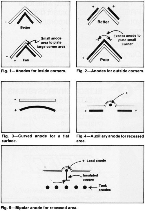
Anodes should generally conform to the shape of the cathode but closer spacing in recesses and wider spacing at corners and edges are suggested (Fig. 1). When anodes are smaller than cathodes in area, the spacing can be increased (Fig. 2). Or, the anodes can be curved to achieve the same effect (Fig. 3).
Although conforming anodes are desirable for plane areas, local auxiliary anodes are frequently preferable to increase deposit thickness in recesses (Fig. 4). Current from a separate source should supply the auxiliaries, to control distribution. Alternatively, the local anode may be bipolar, to simplify racking and plating operations on production fixtures (Fig. 5).
Cathode contacts
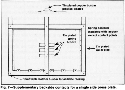
Poorly conducting cathode materials such as Monel or stainless steel, long cylinders and large areas with thin cross section may require compensating contacts to improve thickness distribution. Large thin sheets must have an extensive number of contact points (Fig. 6). To plate one side uniformly, spring-loaded contacts may be required on the back of the sheet (Fig. 7). Good contacts not only improve current distribution uniformity, but also help to prevent hot spots from developing at contact areas. Hot spots generated by undersized, poorly constructed, oxidized or dirty contacts may cause thin deposits, blistering or misplates.
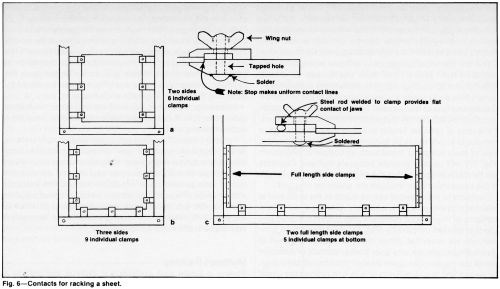
Contact areas should be kept as small as feasible. Electroplated tin (0.0004-0.002 in.) or unbrightened pure nickel (0.005-0.01 in.) on contact surfaces resists oxidation and corrosion. Bare copper is not recommended because it dissolves readily in chromic acid solutions. Thin sections of poorly conducting or readily oxidizable metals require special consideration when fixtures or racks are designed. Contacts must be large enough to carry the required current and dissipate heat generated at the contact. Although the space available for making contacts is often limited, a well-designed rack can dissipate enough heat to permit almost any part to be plated satisfactorily.
Readily oxidizable metals should be clamped with sharply edged or pointed jaws whenever possible. Contact surfaces on both the fixture and workpiece should be cleaned immediately before racking. Failure to observe this rule may result in bare areas or thin or discolored deposits at the contact area or in the center of large sheets.
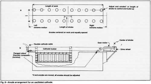
Thin cathodes constructed of high resistance materials exacerbate normal distribution problems. Several methods of correcting distribution may be required in this case. In addition to the methods described above, anode or cathode movement may be necessary (Fig. 8). With the adoption of a moving cathode to improve distribution and eliminate coverage problems, smaller or fewer anodes may be used, less voltage and less current may be required, anode-cathode spacing may be widened and a higher local current density may be possible without risk of overheating the contacts or workpiece. The disadvantages of moving the cathodes include high initial cost, more complex engineering, longer plating time and longer tanks for horizontal plating or extra headroom for vertical plating.
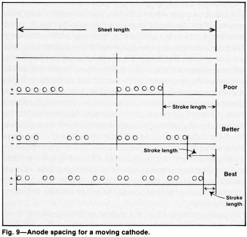
The rate of electrode travel should be adjusted to traverse the area to be plated in less than 10 sec, which is fast enough to avoid oxidation in a sulfate-catalyzed bath. At high temperatures (e.g. above 140°F or 60°C), or in solutions with a fluoride catalyst, the traversing speed may be slower. However, too sluggish a rate may result in poor adhesion or poor coverage. If anodes are spaced as indicated in Fig. 9 while long sheets are plated on a moving cathode, the current will be reduced to a fraction of that needed to plate the part on a stationary cathode. This can compensate for limited power capacity, increase the local current density and accelerate coverage of the workpiece. The improved solution movement tends to avoid local overheating of the solution and improves control of current distribution. These advantages often justify the increased cost of moving the cathode.
Plating inside surfaces of long cylinders
When the inside diameters of long cylinders are plated, the anode current density will always be greater than the cathode current density. Thus, the permissible anode current density must be determined before the cathode current density is selected. If an acceptable cathode current density cannot be identified without exceeding the maximum allowable anode current density or the total applied current, a custom anode design will be necessary.
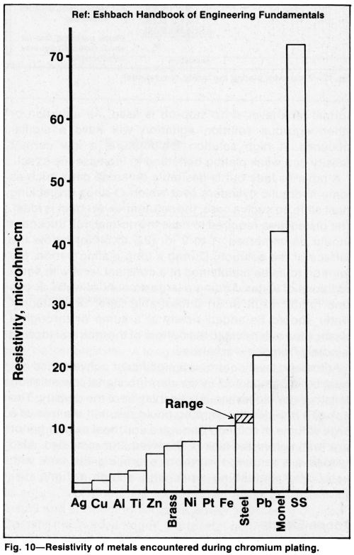
The low electrical conductivity and low strength of lead and lead-rich alloys limit their usefulness as anode materials for ID plating. Aging increases the resistance to current flow and a tendency to warping due to the formation of scale and loss of lead caused by erosion of lead peroxide and could be affected by metal recrystallization, if it occurs. If the ratio of cylinder length to inside diameter is large, a composite anode made by burning a suitable lead alloy to a core of low-resistance metal such as copper or aluminum (Fig. 10) will usually provide adequate current. Contacts can be made at each end of the anode to reduce the length of the conductive path through the anode by one half.
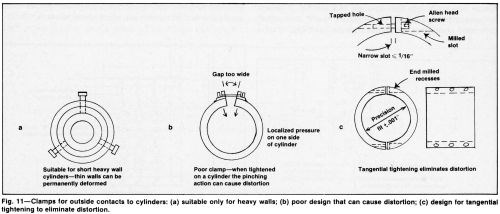
Contacts to the cylinder can be made at the ends and at selected midway points, if necessary. Clamps or set-screw contacts to thin-walled cylinders may distort the bore and affect thickness uniformity (Fig. 11). However, tight connections are essential. When multiple anodes are used to plate a single cathode, one poor busbar contact or defective anode connection can upset deposit thickness distribution. Close spacing (e.g., 6 to 8 mm or 1/4 to 3/8 in.) allows the use of a larger anode but increases the risk of touching and damaging the cathode surface during racking and the danger of poor distribution caused by a small degree of misalignment. These risks can be eliminated or at least minimized by attaching a plastic locating disc to the bottom of the anode, inserting plastic buttons in the anode surface or introducing a temporary split tube of clean paper into the bore before the anode is inserted.
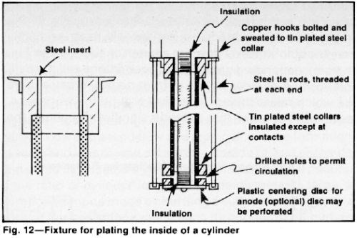
To prevent thickness build-up at the ends of the cylinder, conductive extensions can be attached. Such extensions provide convenient contact areas. They can be stripped after each cycle, by using inhibited hydrochloric acid. Extensions can be integrated with the plating fixture (Fig. 12) for high-volume production. Allowing exposed anode area into the extensions is customary in this case.
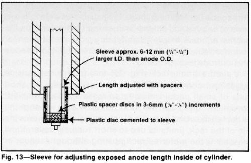
Reasonably good distribution can be achieved when no extensions are used by stopping off the ends of the anode opposite the ends of the cathode cylinder. To facilitate the attachment of electrical contacts and provide the option of using extensions, the anode should be longer than the cylinder. Unexposed end areas (Fig. 13) can be varied by adjusting the length of plastic end shields.
Stepped or tapered anode ends are useful for minimizing axial distortion. It is a simple matter to remove metal for a second plating trial.
Forced circulation through open-ended cylinders is rarely required because gas evolution supplies considerable solution movement. However, forced circulation replenishes chromate ions more rapidly and permits the use of less concentrated solutions without the cathode efficiency decline experienced with a concentrated solution such as 400 g/L of chromic acid. Forced circulation is imperative for high speed plating to achieve a deposition rate above 0.005 in./hr (0.13 mm/hr).
Multipart racking
Plating a single part uniformly is difficult but plating a uniform thickness on a rack full of many parts is even more difficult. Surprisingly, some platers are successful. These platers take advantage of the following observations.
Parts shade or steal current from each other. Thus, deposits on adjacent surfaces will be too thin if the surfaces are too close together. On the other hand, spacing sharp corners and edges close to the edges of adjacent parts helps to improve thickness distribution. If parts of equal dimensions are stacked directly above one another, they can be closely spaced or may even touch each other, to eliminate end build-up. The closest practical spacing produces the maximum number of parts from a given volume of solution.
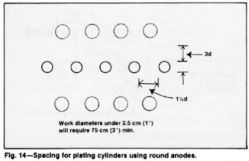
Cylindrical parts with a diameter greater than 1.0 in. (2.5 cm) spaced at least 1.5 times their diameter between two rows of anodes and at least three times their diameter from the nearest anode will have a satisfactory radial distribution for commercial quality. Figure 14 illustrates a suitable anode and cathode arrangement.
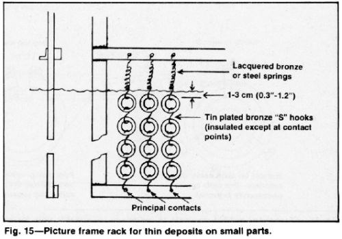
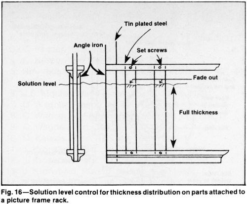
A picture frame rack (Fig. 15) that guards the outside edges and corners of parts is especially useful for short runs of small parts. Uninsulated racks are permissible if chromium build-up will not be excessive during the expected life of the rack. Costly stripping, that shortens the life of the rack, limits its use to short runs, however. Vinyl plastisol is the preferred rack coating although lacquer or tape is acceptable for infrequently used racks. An insulated frame with removable guards or conforming anodes is effective for avoiding excessive current robbing. In this case, the solution level (Fig. 16) is a better current shield than a crossbar, which could entrap gas. This design permits the use of hardened steel or bronze springs above the solution for contact and tension. However, such springs should be lacquered because they are subject to corrosion and embrittlement.
Solution level effects
When the cathode surface approaches or intercepts the solution level, the deposit thickness will taper gradually from the solution level down to a depth of about 0.4 to 2 in. (1-5 cm), depending on the plating conditions and the bath composition. Increasing the current density creates more gas which raises the solution level around the workpiece, resulting in a taper that extends significantly above the normal tank level, if no stop-off is used. Air agitation or other vigorous solution agitation will have a similar influence. A high solution temperature, a low current density or a weak plating bath tend to increase the effect.
A taper or fade out is desirable on some parts such as some hydraulic cylinders over which O-rings or packing must slide. In such a case, the solution-level effect is ideal. The plated area required to have the normal, full thickness should be immersed 1 to 2 in. (2.5 to 5 cm) below the surface of the solution. During a long plating period, the solution must be maintained at a constant level with small additions of water. Adding a large amount of water at one time might result in an undesirable taper or blistering. Water should be added slowly at a sump or through a plastic pipe extending to the bottom of the tank and located remotely from the workpiece.
Automatic level control is a significant convenience but must be accompanied by an alarm to signal low solution density or by close manual observation of the density. The lack of a low-density warning could result in the loss of a large volume of solution through a coil, heat exchanger or tank wall before the leak is observed and remedied. Also needed are sensors to prevent overfilling the tank with water after unloading work with a high volume displacement.
Anode effects
A cathode bar is commonly centered over the tank while anode bars are located along each side of the tank. Perpendicular, adjustable anode bars (Fig. 17) permit anode arrangements that can be tailored for different cathode arrays. Square, rectangular, round and other geometric anode configurations provide flexibility.
Insulated sidewalls and the bottom of the tank improve current distribution in the same way that the walls and bottom of the Haring-Blum throwing power cell16,17 function. Fixtures and workpieces must avoid proximity to any sediment at the bottom of the tank, however. Solution filtration and frequent tank cleaning will eliminate such sediment.
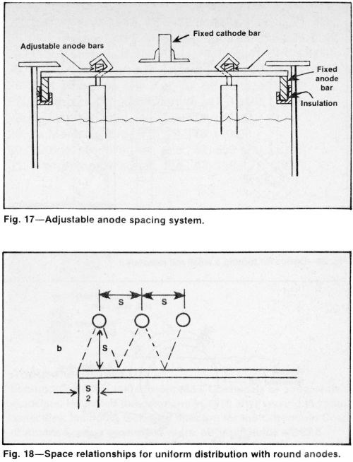
Although conforming anodes provide the best distribution, tank anodes often can be used to obtain adequate results. They are more economical, simplify racking and accelerate loading, unloading, racking and unracking. They accommodate a wide variety of cathode shapes and provide greater flexibility. To use tank anodes effectively, remove excess anodes from the tank and make the anode area equal to or smaller than that of the cathode. Anodes should be properly spaced to avoid blocking solution flow. Close spacing also can cause too much current to be drawn from the front surfaces of the anodes. Too low an anode current density promotes scale formation on lead anodes. Round anodes can be spaced from one another at the same distance as that between the workpieces and the anodes for obtaining uniform distribution (Fig. 18). Using fewer anodes and a wider spacing increases the average anode current density, minimizes the trivalent chromium build-up in concentration, prolongs anode life and promotes improved solution flow.
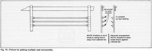
Anodes at the ends of the tank should be indented from the ends of the plating racks, as shown in Fig. 19. The optimum indentation will vary but should be at least half the distance between the anodes and cathodes. Expanded, grid-like and perforated anodes are satisfactory for most applications. Flat anodes are more prone to warp.
Solution agitation
Uniform solution flow past the work surfaces provides an adequate supply of metal anions and helps maintain uniform temperature, which is essential for good thickness distribution. An increase in the temperature of solution adjacent to the cathode, which can be as much as 5°C higher than the average solution temperature, causes a significant reduction in cathode efficiency. Pumping filtered solution through a well-designed sparger system is the best form of agitation.
Gas generated at the electrode surfaces creates some solution agitation but is frequently inadequate for uniform solution movement, especially in recesses and inside corners. As a result, deposits are too thin where gas collects and inhibits deposition. Shading and gas streaking that occur at machined holes are avoided by stopping off these areas.
Vertical vs. horizontal plating
Vertical and horizontal plating systems have distinctly different distribution problems. With the vertical process, racking is simple for short or medium-length parts; tank loading is rapid and hydrogen bubbles are quickly released. The vertical system is suited for inside plating because particles suspended in solution do not readily adhere to vertical surfaces; hydrogen escapes easily from vertical slots, grooves, keyways and flutes. Neither the anode nor cathode is prone to sag and plating time is typically short.
Disadvantages for vertical systems include the need for a large power supply and a deep pit or a high headroom. Introducing current to the bottom end of the workpiece may be troublesome. A long workpiece is difficult to center between anodes. If short pieces are plated with long anodes, unused anode area tends to scale and forms a nonconductive coating. Long anodes are prone to warp unless rotated at regular intervals, are difficult to inspect and require a hoist for examination.
Horizontal systems facilitate contacts at both ends of the work. More than one part can be plated at a time with simple racks (Fig. 19). Anode-cathode spacing generally is easier to adjust. Local anodes for recessed areas are easier to install and connect to separate power sources, if desired. Despite these advantages, horizontal plating is limited to thin deposits unless fixtures can be oscillated or rotated because unagitated parts are prone to pit on bottom areas or become rough on top surfaces. Horizontal processes require more floor space and can result in an inferior radial distribution. Some shops install both types of systems in order to capitalize on the advantages of each.
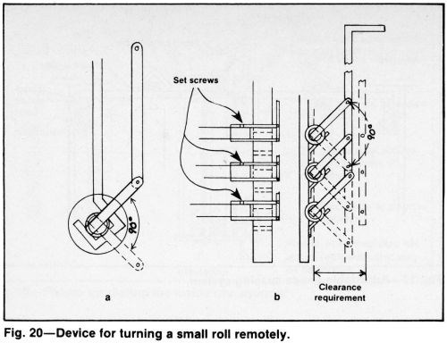
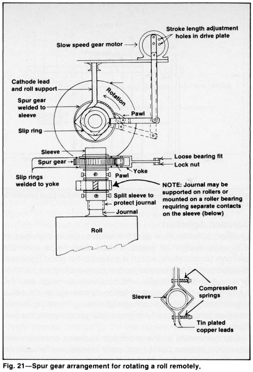
Still plating problems can be alleviated by supporting the work on reciprocating cathode bars. Paddle agitation is more effective for eliminating gas pitting and top surface roughness. A simple version of work rotation involves turning the workpiece 90° at least once during the cycle by an operator wearing a long acid-resistant glove. The part can be turned remotely by periodically raising and lowering an arm attached to a sleeve (Fig. 20). A spur gear can be attached to the end of a shaft to turn it manually or with a low-geared motor (Fig. 21). A roller chain drive is another alternative. Uniform metal distribution is possible with horizontal rotation and suitable anode-cathode spacing. The size and location of anodes can be quickly changed to accommodate different parts.
A slowly rotating cylinder can be inspected during the plating cycle if it is only partially covered by the plating solution (Fig. 22). Deposit thickness can be checked with a magnetic-type instrument or a preset limit gage with plastic tips can be used (Fig. 22) to indicate the increase in the diameter without interrupting the plating cycle.
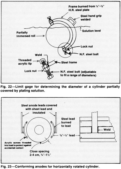
Although horizontal rotation requires more costly fixtures than still plating, the expense is justified if specifications require a uniform thickness distribution. The achievable accuracy often eliminates the need for grinding the deposit. Even when cylinders are ground after plating, grinding costs can be reduced due to the improved uniformity of the rotated cylinders. Conforming anodes attached to the rack on each side of the cylinder can produce superlative axial distribution (Fig. 23).
Designing parts for plating
By providing ample radii, tapers and fillets on parts to be chromium plated, the design engineer can eliminate or minimize many of the most difficult plating problems. The plater can make specific suggestions after measuring or estimating thickness distribution and then suggesting the degree of taper or radius desired. However, he should take all reasonable precautions to correct distribution distortions before appealing for relief. If the designer or manufacturer cannot accommodate his request, the plater should accept any relief that is offered. A small radius is always better than a sharp corner.
Acknowledgment
The author is indebted to Dr. H. Chessin for his encouragement to prepare the paper and for his valuable suggestions and comments.
References
1. C. Kasper, Monthly Review AES, 26, 11-26, 91-109, (1939).
2. C. Kasper, Trans. Electrochem. Soc., 77, 353-383.
3. C. Kasper, ibid., 78, 131-161, (1941).
4. C. Kasper, ibid., 82, 153-165, (1942).
5. R.A. Schaefer, and J.B. Mohler, ibid., 86, 431-440 (1944).
6. J.B. Mohler, Metal Finishing, 79, 74-75, (1981).
7. C. Wagner, Plating, 48, 997-1002, (1961).
8. C. Wagner, J. Electrochem. Soc., 98, 110, (1951).
9. C. Wagner, ibid., 101, 225-228 (1954).
10. O. Kardos, Proc. AES, 43, 181, (1956).
11. J. Kronsbein, ibid., 36, 229-239 (1949).
12. J. Kronsbein, ibid., 37, 279-283 (1950).
13. J. Kronsbein, Plating, 37, 851-854, (1950).
14. J. Kronsbein, ibid., 40, 898-900, (1953).
15. R.O. Hull, Proc. AES, 27, 52, (1939).
16. H.E. Haring and W. Blum, Trans. Electrochem. Soc., 44, 313-345 (1923).
17. H.L. Farber and W. Blum, Bur. of Stds. J. Res., 4, 27-53, (1930).
18. J.D. Thomas et al., Proc. AES, 47, 94, (1960).
19. J.B. Mohler, Monthly Rev. AES, 34, 1361, (1947).
20. J.B. Mohler, Plating, 39, 475, (1952).
21. R. Gilmont and R. Walton, Trans. Electrochem Soc., 103, 549, (1956).
22. L.C. Pan, ibid., 58, 423-432, (1930).
23. W.L. Pinner and E.M. Baker, ibid., 55, 315-325, (1929).
24. G.F. Kinney and J.V. Festa, Plating, 41, 381, (1954).
25. J.J. Christie and J.D. Thomas, ibid., 52, 855, (1965).
26. R.H. Rouselot, Met. Fin., 57, 56, (Oct. 1959).
27. E. Mantzell, Z. Electrochem., 41, 10-20, (1935).
28. E. Mantzell, ibid., 42, 303-315, (1936).
29. E. Mantzell, ibid., 43, 174-176, (1937).
30. Kangro and Wagner, ibid., 42, 659-669, (1936).
31. Kangro and Wagner, ibid., 43, 119-127, (1937).
About the Author

Edmund C. Knill is retired from M&T Chemicals as a research associate. He joined the company in 1970 after serving in various capacities, including technical director, for the Chromium Corp. of America over a span of 30 years. Mr. Knill holds a B.Ch.E. degree from Clarkson College and was a member of the AESF Newark Branch.
Related Content
Practical Observations in Surface Chemistry and Boundary Layer Control to Enable Scalable Electrochemical Operation - The 57th William Blum Lecture
This paper is based on the 57th William Blum Memorial Lecture at SUR/FIN 2023, in Cleveland, Ohio on June 8, 2023, by Dr. Tim Hall, recipient of the 2023 NASF Scientific Achievement Award. It focuses on the practical effects of controlling the boundary and surface chemistry on a wide range of electrochemical applications. After a brief introduction to the concept and principles of surface and boundary layer properties during electrochemical processes, the use of this approach in controlling various physical properties during electroplating and electrochemical finishing is discussed, including controlling coating stress and metal composition, as well as enabling simple water-based electrolytes to polish passive or complex materials.
Read MoreTin-Zinc Alloy Electroplating and Its Corrosion Behavior
An NASF/AESF Foundation Research Program Retrospective
Read MoreNASF/AESF Foundation Research Project #121: Development of a Sustainability Metrics System and a Technical Solution Method for Sustainable Metal Finishing - 15th Quarterly Report
This NASF-AESF Foundation research project report covers the twelfth quarter of project work (October-December 2023) at Wayne State University in Detroit. In this period, our main effort focused on the development of a set of Digital Twins (DTs) using the Physics-Informed Neural Network (PINN) technology with application on parts rinsing simulation.
Read MoreRead Next
Episode 45: An Interview with Chandler Mancuso, MacDermid Envio Solutions
Chandler Mancuso, technical director with MacDermid Envio discusses updating your wastewater treatment system and implementing materials recycling solutions to increase efficiencies, control costs and reduce environmental impact.
Read MoreDelivering Increased Benefits to Greenhouse Films
Baystar's Borstar technology is helping customers deliver better, more reliable production methods to greenhouse agriculture.
Read MoreA ‘Clean’ Agenda Offers Unique Presentations in Chicago
The 2024 Parts Cleaning Conference, co-located with the International Manufacturing Technology Show, includes presentations by several speakers who are new to the conference and topics that have not been covered in past editions of this event.
Read More


