Improving the Wear Performance of Functional Trivalent Chromium Plating Via Pulse-Reverse Electrodeposition
This paper covers work on improving the wear performance of a functional chromium coating from a trivalent chromium plating bath. Wear resistance is a critical aspect of chromium coatings when used in components of both ground-based and aerospace vehicle systems. Traditional hexavalent chromium coatings have shown exceptional wear resistance in these applications, while the wear resistance of trivalent chromium coatings has been less satisfactory. Using pulse-reverse electrodeposition to control various characteristics of the chromium coating, the wear performance of trivalent chromium plated panels could be improved. A multivariate regression model of the electrodeposition conditions shows that bath chemistry parameters within the range of viable plating are not a large contributor to the variance in wear performance, while the roughness and size of macro-cracks is very important for wear-related applications. The multivariate analysis approach undertaken in this study may find potential applications in broad areas of the plating and finishing industry.
byAndrew Moran,1* Timothy Hall,1 Rajeswaran Radhakrishnan,1 Maria Inman,1 E.J. Taylor,1 Mark Feathers,2 Michael Johnson2 and George Bokisa3
1 Faraday Technology, Inc., Englewood, Ohio, USA
2 U.S. Army Aviation and Missile Command, Redstone Arsenal, Alabama, USA
3 (MacDermid Enthone / Coventya) Brooklyn Heights, Ohio, USA
Editor’s Note: A printable PDF version of this report is available by clicking HERE.
ABSTRACT
We will discuss recent work on improving the wear performance of a functional chromium coating from a trivalent chromium plating bath. Wear resistance is a critical aspect of chromium coatings when used in components of both ground-based and aerospace vehicle systems. Traditional hexavalent chromium coatings have shown exceptional wear resistance in these applications, while the wear resistance of trivalent chromium coatings has been less satisfactory. Given the highly toxic nature of the hexavalent chromium plating process, it is desirable to improve the wear performance of trivalent chromium coatings. Using a pulse-reverse electrodeposition approach to control various characteristics of the chromium coating, we have demonstrated that the wear performance of trivalent chromium plated panels could be improved. A multivariate regression model of the electrodeposition conditions shows that bath chemistry parameters within the range of viable plating are not a large contributor to the variance in wear performance, while the roughness and size of macro-cracks is very important for wear-related applications. A discussion of the atomic composition of trivalent chromium coatings as it relates to macro-cracks, wear performance and overall microstructure is provided. The multivariate analysis approach undertaken in this study may find potential applications in broad areas of the plating and finishing industry.
Introduction
Functional chromium coatings offer hard durable surface protection with a low coefficient of friction and are often used for enhanced wear resistance of interacting surfaces on critical components in automotive, aerospace and mining applications.1 Functional chromium coatings are differentiated from decorative chromium coatings by an appreciable thickness in the range of 20-500 μm, depending on the application.2 To achieve the thicknesses required for functional applications, electrodeposition techniques usually rely on hexavalent chromium chemistries. This presents safety challenges related to the highly toxic and carcinogenic nature of hexavalent chromium.3 On the other hand, trivalent chromium is a relatively non-toxic ionic form of chromium4 that can also be used for safe and environmentally-friendly chromium electrodeposition.5 While decorative trivalent chromium has enjoyed widespread commercial usage, functional chromium coatings from trivalent chemistries have been impeded by coating thickness limitations and poor performance in critical applications.
In previously reported work, personnel at Faraday Technology progressively advanced the state-of-the-art of trivalent chromium plating in several ways, including the ability to plate from a chromium sulfate chemistry, increasing the plating thickness up to 500 μm, and maintaining economically-relevant plating rates.6 They have also showed the advantages of pulse/pulse reverse current operation on the trivalent chromium electrodeposition process. These advantages include control of surface pH and mass transfer during the plating process. This work was then leveraged to demonstrate the use of an environmentally benign trivalent chromium chemistry for coating complex, hard-to-access surfaces such as the interior of landing gears.7 Recently, the use of pulse/ pulse reverse in trivalent chromium electrodeposition has shown an ability to achieve greater control over the formation of internal stresses in the coating as a result of the destruction of secondary phases and impurities during plating.8
Despite the progress in trivalent chromium electrodeposition, several hurdles prevent the widespread adoption as a drop-in replacement for conventional functional chromium applications. The primary obstacles for adoption are the continued existence of macro-cracks (defined here as cracks extending in the short-transverse direction with a length similar to the coating thickness) and a poorer wear resistance than conventional hexavalent chromium coatings. In this study, we report on the progress made in improving the wear-related performance of trivalent chromium coatings through pulse/pulse reverse electrodeposition. A progressive approach to designing new pulse/pulse-reverse waveforms for the application of trivalent chromium was successful in improving the appearance, morphology and wear resistance of plated panels.
Technical approach
Trivalent chromium chemistry
The trivalent chromium bath was composed of a proprietary neutral boric acid free electrolyte.** The solution was prepared using deionized water and pH maintained at 5.2 - 5.4 with either H2SO4 or NH4OH. Each week of the plating period, the bath chemistry was analyzed for several components and then partially replenished by replacing 20 L from a 600 L tank with a nominally identical ratio of constituents. This “bleed and feed” procedure was implemented in order to replenish the electrolyte and maintain the bath chemistry as recommended by the supplier. The bath chemistry parameters tested each week were the chromium concentration (g/L), the concentration of complexant as a percent of total electrolyte volume (CPLX %), the surface tension in dynes/cm, and pH. In addition, iron, zinc, nickel and copper concentrations were measured each week.
Electrodeposition
Electrodeposition was carried out in a 600 L tank using flat panel mixed-metal-oxide (MMO) anodes. Two sides of a 4” × 6” 4130 steel panel comprised the cathode plating surface. Plastic shielding was used to focus current on the 4” × 6” panel to achieve a uniform thickness and avoid edge effects. After plating, the 4” × 6” panels were cut to a 4” × 4” size for Taber Abrasion testing. Figure 1A shows an image of the tank with the arrangement of anode, cathodes, eductors, flow ramps and shielding. Figure 1B shows an image of a 4” × 6” steel panel after electrodeposition.
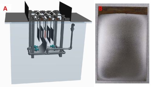
Figure 1 - (A) Image of the trivalent chromium plating tank and (B) image of a 4" × 6" steel panel after electrodeposition.
Pretreatment of panels consisted of an alumina grit-blast, rinsing with acetone and ethanol, followed by an alkaline pumice scrub immediately prior to plating. The 4” × 6” panels were plated using both direct current (DC) and pulse-reverse current (PRC). Panels were put into the trivalent chromium bath using a hot entry method, where a low voltage was applied to the panel prior to entering the solution so that it was cathodically protected from oxidation during entry. Hot entry used a current density of 2.5 A/in.2 for 2 minutes. After hot entry, the electrodeposition current was initiated. In this study, we report the use of two separate trivalent chromium baths, termed Bath #1 and Bath #2. Both baths were identical in composition at the time of origination. Each week during the period of study, a panel was DC plated at 3 A/in.2. This panel is called the “Monday Repeat” and was intended to demonstrate the variability of wear performance on a week-to-week basis. This current density had been previously recognized through Hull Cell experiments as providing optimal current efficiency.7 PRC plating was conducted on multiple panels each week by varying the waveform parameters as described in the “Pulse-Reverse Electrodeposition” section.
All plated specimens underwent a hydrogen embrittlement relief bake at 190°C (375°F) for 24 hours post-plating, before performing the Taber abrasion tests. This bake is standard practice in the chromium plating industry. The Taber abrasion test was performed according to ASTM D4060, using CS-17 wheels and 100-g loads for 11,000 cycles. The results are reported as a wear index number (Wear Index 2) denoting the mass loss (mg) from 1000 to 11,000 cycles. The Vickers microhardness of specimens was determined through nano-indentation in accordance with ASTM E384. The microstructure and morphology of the trivalent chromium coating was analyzed through light microscopy and SEM of the normal surface as well as cross-sectioned profiles. The standard roughness parameters, Ra and Rz, were assessed with a Mitutoyo SJ-400 line profilometer.
Pulse-reverse electrodeposition
Faraday has utilized pulse- and pulse-reverse waveforms for trivalent chromium electrodeposition. Figure 2 is an example of a pulse- and pulse-reverse waveform, consisting of a cathodic (forward) pulse followed by an anodic (reverse) pulse and an off-time. The cathodic peak current (ic), cathodic on-time (tc), anodic peak current (ia), anodic on-time (ta), and the off-time (to) are individual variables for process control. The sum of the cathodic on-time, anodic on-time, and off-time is the period of the pulse and the inverse of the period is the frequency. The cathodic duty cycle (γc ) is the ratio of the cathodic on-time to the period, and the ratio of the anodic on-time to the period is the anodic duty cycle (γa). The frequency and duty cycles are additional variables for process control. The average current density (iaver) or electrodeposition rate is given by:
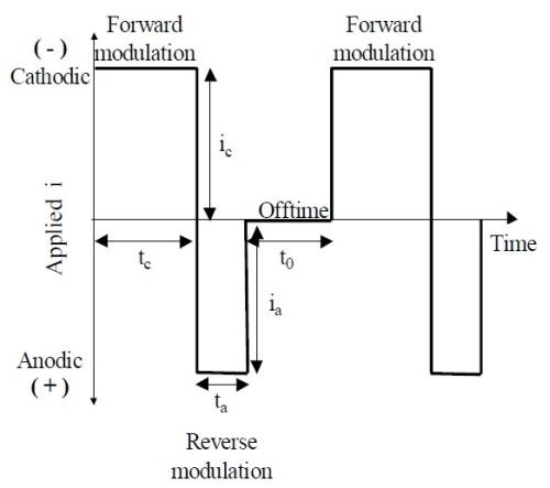
Figure 2 - Generic pulse- and pulse-reverse waveform.
iaver = icγc - iaγa (1)
Just as there are infinite combinations of height, width and length to obtain a given volume, in pulse-reverse processes, there are unlimited combinations of peak current densities, duty cycles and frequencies to obtain a given electrodeposition rate. By controlling the cathodic and anodic on-time, relaxation-time and the cathodic and anodic peak currents, precise control of the electrodeposition process is achieved, and the properties of the resulting deposit may be controlled or fine-tuned for a specific application. In conventional direct current (DC) electrodeposition, the current is turned on and held for the duration of the process. By interrupting this constant stream of current, as in the pulse- and pulse-reverse process, one may achieve results not possible with conventional DC electrodeposition, such as deposit property control, and the elimination of adverse side reactions such as hydrogen evolution.
In this study, PRC was used to plate 4” × 6” specimens for Taber abrasion testing. The precise PRC conditions used in each test are retained as proprietary information. PRC testing involved waveform combinations of various forward and reverse modulations of both applied voltage and on/off timing. Additionally, some complex waveforms were used where a multi-step modulation of several forward and reverse pulses were applied. Waveform modulations were generally in a frequency window of 1-10 Hz.
Results and discussion
The plating activities reported here took place in two separate instances of a trivalent chromium bath. This is worth pointing out given the uncertainty around bath stability and variability of performance. In other words, one purpose of these activities was to examine the long-term variability of the trivalent chromium bath in terms of the wear performance of plated parts. Another goal was to improve this wear performance using PRC electrodeposition as opposed to a DC process. Regarding these two goals, Figures 3 and 4 chart the wear performance (Taber Wear Index 2 (WI2)) of a weekly repeat of the DC plating condition as well as various PRC conditions. Figure 3 pertains to “Bath #1” during the period between January 22, 2020 to October 7, 2020 while Figure 4 pertains to “Bath #2” during the period between April 15, 2021 to October 11, 2021.
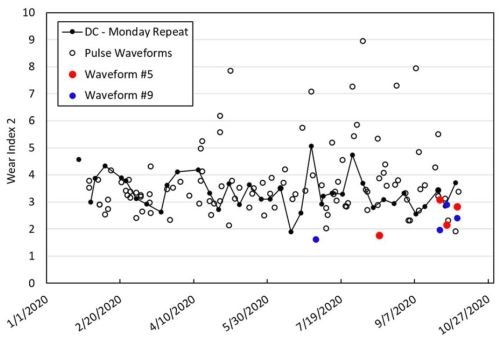
Figure 3 - Graph of wear performance of trivalent chromium plated 4" × 6" panels in Bath #1 over a 10-month period from January 22, 2020 to October 7, 2020.

Figure 4 - Graph of wear performance of trivalent chromium-plated 4" × 6" panels in Bath #2 over a 10-month period from April 15, 2021, to October 11, 2021.
Wear performance
The use of a Taber wear index in this study allows for comparison to the state-of-the-art of wear-resistant hexavalent chromium coatings. The Taber WI2 of hexavalent chromium coatings is generally under 1.0, representing a baseline of less than 1.0 mg of mass loss after 10,000 cycles (specifically, cycles 1,000 to 11,000) in a Taber abrasion test. It is worth noting here that this study is concerned primarily with the wear performance of trivalent chromium panels after a hydrogen embrittlement relief bake. For comparison, two panels plated with the trivalent chromium process (both DC and PRC) were tested in the as-plated state with a Taber abrasion test and had a WI2 of less than 1.0. This demonstrates performance comparable with hexavalent chromium (whether as-plated or baked). Except for these two specimens, all other specimens plated with the trivalent chromium process underwent a hydrogen embrittlement relief bake. While the wear performance of the baked trivalent chromium coating did not match the wear performance of hexavalent or trivalent as-plated coatings, significant improvements were nonetheless made through PRC plating.
The weekly repeated DC plating condition is tracked in both Bath #1 and Bath #2 as indicated in Figures 3 and 4 by the “DC – Monday Repeat” label. In both baths, DC plated specimens showed a variability in their wear performance, despite nominally identical coating appearances and thickness in the range of 3-4 mils. Overall, the wear performance of DC specimens plated in Bath #1 was superior to those plated in Bath #2.
Over the ten-month testing period in Bath #1, more than two dozen panels were plated with varying PRC waveforms and subsequently tested for wear performance. Many PRC conditions led to insufficiently thick coatings (at least 2 mil (0.002”)) for wear performance testing. Figure 3 shows results only for those panels with a sufficiently thick and adherent coating for wear testing. From tracking the Taber wear index, we observe that several PRC conditions were able to achieve significantly improved wear resistance as compared to DC plating. We noted that two conditions, termed Waveform #5 and Waveform #9, seemed especially promising. Toward the end of the lifetime of Bath #1, Waveforms #5 and #9 were repeated in order to assess their variability. The average WI2 of the DC condition and Waveforms #5 and #9 in Bath #1 are included in Table 1. These data demonstrate the improved wear performance of PRC plated specimens, especially when plated using Waveform #9.

Table 1 - Comparison of WI2 in Bath #1 to Bath #2 for three plating conditions.
Figure 3 charts the WI2 of DC Monday repeats as well as various PRC waveforms over the lifetime of Bath #1 and Figure 4 includes the average WI2 of the DC condition and Waveforms #5 and #9 in Bath #2. Similar to Bath #1, Waveform #9 consistently out-performs the DC plating condition on a weekly basis. Waveform #5 did not perform as well in Bath #2 as in Bath #1, but this may be an outlier due to a lack of data in this bath.
In Bath #2 we performed a systematic study of variations of the best-performing waveforms from Bath #1 to downselect PRC conditions for the enhancement of wear resistance. Waveforms #5 and #9 were modified to study the effect of small variations on waveforms that had already displayed good wear performance. There is a wide deviation of performance of modified waveforms during this plating period with some modified waveforms out-performing the DC condition and several approaching a WI2 of 2.0. In depth investigations on these modified waveforms, especially as it relates to their potential to attain a consistent WI2 of around 2.0, are ongoing.
Multivariate analysis
In Bath #1 (Fig. 3), we observed that the DC condition has an inherent variability in the wear performance of plated panels. The Taber index WI2 for “DC – Monday Repeats” varied from 2 to 5 over the course of the ten-month period of performance. This variability is also observed in Bath #2, as shown in Figure 4. This variability implies that there is either deviation in the plating process or deviation inherent in the Taber testing.
To rule out the effect of variability in the Taber abrasion test, its repeatability was validated by intra-weekly repeats of the DC plating condition. Across four panels plated in the same week, the WI2 had a deviation of ± 0.4. A second and third intra-weekly test between an additional two panels showed a deviation of just 0.1 units and a fourth intra-weekly test showed a dispersion of 0.29. A rigorous study of the statistical dispersion of WI2 from the Taber abrasion test was not performed, but given the repeatability across the intra-weekly samples, we felt confident to conclude that the Taber abrasion test will be accurate to within 0.4 units. Given the repeatability of the Taber abrasion test, it can be concluded that this test itself is not the primary source of variability in the weekly DC Monday Repeats.

Figure 5 - Groupings of variables tracked during the plating process that may influence the Taber wear resistance of plated samples.
Over the course of the lifetimes of Baths #1 and #2, several chemical parameters were tracked on a weekly basis. Because the trivalent chemistry was subjected to a weekly partial replenishment (“bleed and feed”), this timescale was the most relevant in terms of measuring large changes in the chemistry. The second column of Figure 5 shows the bath chemistry parameters that were measured on a weekly basis. “CPLX” denotes the percentage concentration of complexant in the bath. To elucidate the effect that bath chemistry has on the wear performance of plated panels, the effects of the bath characteristics were analyzed using single-variable and multivariate regression. The single-variable regression model considered the bath chemistry factors as the input and the WI2 as a dependent variable. The linear expression for a single-variable model is the following:
WI2 = AP1 + C (2)
where WI2 is the independent variable (output variable), the 2nd wear index of the Taber wear resistance test, A is a coefficient of the input variable, P1 (bath chemistry parameter), and C is a constant. Calculating the coefficients of this model was executed using the Python programming language and “statsmodels” module to implement an Ordinary Least Squares (OLS) method of linear regression.
Table 2 tabulates the correlation coefficients between four bath chemistry parameters and the WI2 for DC conditions (corresponding to Figure 3) as well as Waveform #5 and Waveform #9. The correlation coefficients are fairly low in this case indicating that single bath chemistry variables have low explanatory power for the variance in wear performance of plated panels. The largest correlation coefficient of a bath chemistry variable is for the concentration of chromium related to plating using Waveform #5. For this waveform, we can conclude that chromium concentration explains 41% of the variance of the WI2.
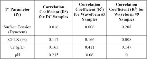
Table 2 - Regression analysis for single parameters associated with bath chemistry characteristics.
It is also possible that multiple variables played a semi-dependent role in the wear performance of plated panels. To investigate this, multivariate regression was used to determine the combined influence of some key variables. The expression underlying the two-factor multivariate linear regression model is as follows:
WI2 = AP1 + BP2 + C (3)
where A and B are coefficients of two input variables, P1 and P2, and C is a constant.
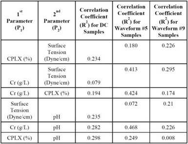
Table 3 - A subset of all parameter pairs of the bath chemistry and correlation coefficients for a multivariate regression model of WI2 of samples plated using DC, waveform #5 and waveform #9 in Bath #1.
In Table 3, the correlation coefficients of pairs of variables are plotted as determined by multivariate regression. Here again, the pairs of bath chemistry parameters have low explanatory power when it comes to the variance in the WI2 measure. The only exception being that chromium concentration, when considered in tandem with CPLX, surface tension and pH, can explain approximately 40% of the variance of the WI2 for waveform #5.
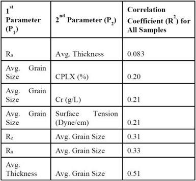
Table 4 - Coating characteristic pairings and corresponding correlation coefficients for all specimens plated in Bath #1.
The low correlations between bath chemistry parameters and wear performance signifies that, within the range of chemistry parameters tested, the variability of wear performance is not strongly related to the variability of the bath chemistry itself. To extend the test of multivariate analysis to include coating characteristics (first column of Fig. 5), another multivariate test was conducted by considering these characteristics as dependent variables. The characteristics considered included roughness (Ra and Rz), thickness and grain size. Grain size in this context refers to the size of grains in the cracking network upon examination of the visible coating, not metallurgical grains (These grains are most visible in Fig. 6C.). In this test, both DC and PRC specimens are included. The correlation coefficients of these parameter pairings are shown in Table 4.
The largest contributor to the variance in wear performance comes from the combined effect of thickness and grain size. We also observe that roughness parameters (Ra and Rz), when paired with “Avg. Grain Size,” can explain up to 30% of the variance of WI2. It should also be pointed out that the correlation between grain size and WI2 is negative; that is, larger grains lead to better wear performance. Since thickness is controllable through plating time, and roughness parameters Ra and Rz are direct functions of electrodeposition conditions, we surmise that much of the wear performance of trivalent chromium plated panels can be improved through more precise control of these parameters. We have observed that PRC panels generally show a larger average grain size than DC panels (approximately 200 μm for PRC vs 160 μm for DC). However, we could not deduce an obvious schema for controlling grain size through waveform control. This area will be investigated in future studies.
This regression model provided the basis for investigating various characteristics of bath chemistry and coating morphology as they relate to wear performance. The model will be used in future investigations as a way to narrow the search for variables of interest in the pursuit of improving wear performance in a trivalent chromium bath. We anticipate that this approach can be broadly useful in the plating industry for greater understanding of the effect of bath chemistry and coating characteristics on various tests of merit.
Microstructure and morphology
In Figure 6, top-down images of the morphology of the coating surface are shown for a variety of plated panels. From top to bottom are images of the coating (taken from the middle of a 4” × 6” panel) before Taber abrasion (A and B), images of the wear track after 11,000 cycles of Taber abrasion testing (C and D), and cross-sections of the panels in a non-wear-track section (E and F).
The morphology of trivalent chromium plating appears in many forms depending on the plating conditions. In the present study, the plating conditions generally led to a smooth coating morphology on the bulk surface of plated panels. Near the edges of panels, the coating tended to form nodules and dendrites. The roughness of plated panels differed noticeably between DC and PRC conditions with PRC conditions, with Waveform #9 having a much smoother surface. A comparison of the average roughness of panels plated with a DC condition and Waveform #5 and #9 is given in Table 5.
Trivalent chromium coatings prepared using an organic ligand are often observed to include interstitials such as carbon, either as a supersaturated constituent or as a chrome carbide. While most investigations on the topic attribute carbon inclusions to the co-reduction of the ligands in the chromium coordination sphere,9 some researchers have suggested an unusual “chemical” mechanism of incorporation.10 Regardless, carbon inclusions are widely observed in trivalent chromium plating processes, with concentrations in the coating ranging from 2-12%. The inclusion of carbon in trivalent chromium films is, in fact, so ubiquitous that studies often alternatively refer to trivalent chromium coatings as Cr-C alloys.11,12 The trivalent chromium coatings prepared in this study were found to possess around 10 wt% carbon.
Macro-cracks are a consistent feature of trivalent chromium coatings. Similarly, macro-cracks were observed on all plated specimens in the present study. As opposed to the distributed small-scale microcracks common in hexavalent chromium coatings, the cracks in trivalent coatings typically manifest as larger through-cracks, extending from the coating surface to the substrate.12,13,14 Some researchers have attributed this cracking behavior to a change in the phase structure of Cr-C from amorphous / microcrystalline to crystalline when undergoing heat treatment. However, we note in this study that cracks are present in the trivalent chromium coating even before heat treatment, though they appear as very fine hairline cracks. The crack network seems to “open up” upon heat treating.12 This phenomenon can be observed in the images in Figure 6. The images in the right-hand column (B, D, F), show the presence of hairline cracks in the chromium coating before heat treating for hydrogen embrittlement relief.
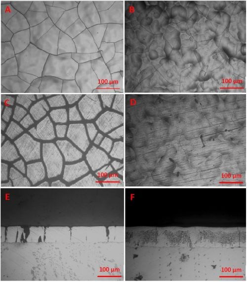
Figure 6 - Top-down images of coating before Taber abrasion testing on baked sample (A) and as-plated sample (B). Top-down images of coating on the Taber abrasion wear-track of baked (C) and as-plated (D) sample. And cross-sections of a baked (E) and as-plated (F) coating. All images at 16× magnification
Mechanism of wear performance improvement
Though PRC plating has enabled a general improvement in the wear performance of trivalent chromium coatings, the precise mechanism that leads to this improvement is still unclear. While a reduction of roughness seems to play a large role in Taber wear resistance testing, it is not the only factor involved. As noted from multivariate analysis, roughness can likely explain about 30% of the variance in wear performance. During testing, we observed that many smooth samples had poor wear performance. Likewise, many rough samples had relatively good wear performance.
The largest visible factor of the wear performance was the grain size of plated panels. This grain size is essentially a measure of the extent of macro-cracking, with smaller grains indicating a more extensive crack pattern. Related to the extent of macro-cracking, panels subjected to a hydrogen embrittlement relief bake tended to display wider macro-cracks than as-plated panels. For example, Figure 6 shows both surface images and cross-sections of a panel in the as-plated state and after a hydrogen embrittlement relief bake. It is possible that the drastic reduction in wear performance of baked panels - as opposed to as-plated panels - is a result of these widened macro-cracks on the surface of the panel providing more points of interaction between the coating and the Taber abrasion wheels. This explanation may also explain why the average grain size of the coatings has such a large effect on wear performance. Controlling grain size, or the extent of macro-cracking, is then a potential direct route for enhancing wear performance.
Previous studies had theorized that reverse pulses during the PRC plating process showed a potential to destroy oxide, hydroxide and/or hydride inclusions that are incorporated during the trivalent chromium plating process.15 The existence of Cr-O and Cr-H species, in addition to Cr-C as discussed above, has been reported in several studies of trivalent chromium electrodeposition.9,11,16 Ahmadi, et al. and Karadavut have shown that decomposing hydride species with either sufficient off-times or sufficient reverse current can reduce the in-situ stress that builds up in trivalent chromium thin films.15,17 This reduction in in-situ stresses during PRC plating could explain the reduction in macro-cracking observed on PRC plated panels, and thus a reduction in wear performance, as explained above.
Despite the improvements in wear performance from PRC plating, macro-cracks do still exist in the trivalent chromium films. We hypothesize that, although PRC can reduce in-situ stresses by destroying oxides/hydroxides and hydrides, the presence of carbides in the trivalent film still creates a brittle crystalline alloy (relative to pure chromium) susceptible to macro-cracking. The brittle fracture mechanism of the coating at the crack origins can be observed in the SEM images shown in Figure 7. Additionally, the hardness and microstructure appear relatively consistent between DC and PRC panels. Both DC and PRC panels had a Vickers hardness of around 800-1000, indicating similar microstructure and composition. A reduction in the overall carbon content of trivalent chromium films may be a worthwhile direction for future research and a more thorough investigation of the precise concentrations of carbon content as a function of DC and PRC conditions is planned.
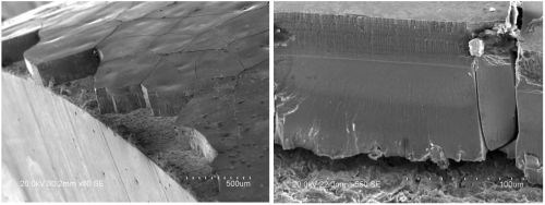
Figure 7 - SEM images of the trivalent chromium coating cross-section.
Conclusions
The wear performance of trivalent chromium plated panels was improved through pulse/pulse-reverse deposition techniques. By progressively examining various facets of complex pulse-reverse waveforms, consistent enhancements to wear performance could be achieved when compared to DC plating conditions. While stability in wear performance remains a challenge with the current trivalent chromium chemistry, a multivariate regression model indicates that bath chemistry components, within the range of viable plating, have a negligible impact on wear performance whereas coating characteristics such as roughness, macro-cracking and thickness play a large role in wear performance. Insofar as such characteristics are important for wear performance, pulse/pulse-reverse plating provides a valuable way to control the deposition process to achieve the desired plating characteristics.
Acknowledgement
This study is supported by U.S. Army (Contract No. W911NF1920329) and commercial sources. Coventya Inc. is providing the boric acid-free REACH compliant chemistry that was used for this work at Faraday. The financial support of Faraday Technology, Inc. corporate research and development is also gratefully acknowledged.
References
1. R.F. Guffie, The Handbook of Hard Chromium Plating, Gardner Publications Inc., USA, 1986.
2. D.T. Gawne, T.F.P. Gudyannga, in: K.H. Strafford, P.K. Datta, C.G. Googan (Eds.), Coatings and Surface Treatment for Corrosion and Wear Resistance, Ellis Horwood, Chichester, UK, 1984, pp. 28–45.
3. https://www.osha.gov/sites/default/files/publications/hexavalent_chromium.pdf
5. Timothy D. Hall, Maria E. Inman and E. Jennings Taylor. "Sustainable Green Processes Enabled by Pulse Electrolytic Principles." The Electrochemical Society Interface 29 (3), 49-54 (2020).
6. T.D. Hall, E.J. Taylor and M. Inman. "Functional Trivalent Chromium Electroplating," Plating & Surface Finishing, 97 (11), 42-48 (2010).
7. Burhanuddin Kagajwala, Timothy D. HaIl, et al., "Functional trivalent chromium electroplating of internal diameters," (Abst.) Products Finishing, 77 (4) 10 (2013); Full paper: http://short.pfonline.com/NASF13Jan1 (Last accessed January 27, 2022).
8. K. Ahmadi and Stanko R. Brankovic, "Crack Formation during Electrodeposition and Post-deposition Aging of Thin Film Coatings." (Abst.) Products Finishing, 84 (2) 13 (2019); Full paper: http://short.pfonline.com/NASF19Nov2 (Last accessed January 27, 2022).
9. Laura Sziráki, et al. "Electrochemical behaviour of amorphous electrodeposited chromium coatings." Materials Chemistry and Physics, 133 (2-3), 1092-1100 (2012).
10. Vyacheslav S. Protsenko, Viktor O. Gordiienko and Felix I. Danilov, "Unusual" chemical" mechanism of carbon co-deposition in Cr-C alloy electrodeposition process from trivalent chromium bath," Electrochemistry Communications, 17, 85-87 (2012).
11. A.A. Edigaryan, et al., "Properties and preparation of amorphous chromium carbide electroplates," Electrochimica Acta, 47 (17), 2775-2786 (2002).
12. Zhixiang Zeng, et al., "Tribological and electrochemical behavior of thick Cr–C alloy coatings electrodeposited in trivalent chromium bath as an alternative to conventional Cr coatings," Electrochimica Acta 52 (3), 1366-1373 (2006).
13. Joo-Yul Lee, Man Kim and Sik-Chol Kwon, "Effect of polyethylene glycol on electrochemically deposited trivalent chromium layers," Transactions of Nonferrous Metals Society of China, 19 (4), 819-823 (2009).
14. Y.B. Song and D-T. Chin, "Current efficiency and polarization behavior of trivalent chromium electrodeposition process," Electrochimica Acta, 48 (4), 349-356 (2002).
15. Kamyar Ahmadia, et al., "NASF/AESF University Funded Research Transitioned to Industry: Practical Performance Improvements in Functional REACH-Compliant Trivalent Chromium Plating," (Abst.) Products Finishing, 84 (7) 12 (2020); Full paper: http://short.pfonline.com/NASF20Apr21 (Last accessed January 28, 2022).
16. Viktor A. Safonov, et al., "Valence-to-core X-ray emission spectroscopy identification of carbide compounds in nanocrystalline Cr coatings deposited from Cr (III) electrolytes containing organic substances." The Journal of Physical Chemistry B, 110 (46), 23192-23196 (2006).
17. OmerFaruk Karadavut, In-Situ Stress Measurements During Electrodeposition of Chromium Films, Dissertation, University of Houston (2018).
About the authors

Dr. Andrew Moran is a Principal Scientist at Faraday Technology Inc. He received his B.S. in Bioengineering (2014) from the University of Toledo, and Ph.D. in Chemical Engineering (2019) from the University of Akron studying the AC corrosion of cathodically protected pipelines. He is working in the areas of electrochemical machining, electrochemical modeling and simulation, and electroplating of trivalent chromium and ZnNi,

Dr. Timothy D. Hall is the Laboratory Manager at Faraday Technology Inc. He received his B.S. in Chemical Engineering and Mathematics from West Virginia University (Morgantown, WV) in 2003, his M.S. and Ph.D. in Chemical Engineering from the University of Notre Dame (Notre Dame, IN) in 2006 and 2007, respectively. Dr. Hall was part of a team that received a 2011 R&D 100 Award, 2013 green chemistry award, and was a 2016 R&D 100 Award finalist in both plating and surface finishing electrochemical technologies. He has been a significant contributor to work that has led to six patents and numerous pending patent applications.

Dr. Rajeswaran Radhakrishnan is a Principal Scientist at Faraday Technology Inc. He received his B. Tech. in Chemical and Electrochemical Engineering from Central Electrochemical Research Institute, India (2009) and a Ph.D. in Materials Science and Engineering from Clarkson University, Potsdam, NY (2015). He is currently working within Faraday’s electropolishing and deposition portfolios; specifically, on electropolishing of passive alloys and electrodeposition of trivalent chromium coatings.

Dr. Maria Inman is the Research Director at Faraday. Dr. Inman leads Faraday’s research and development function. In addition to providing day to day direction to the science and engineering staff at Faraday, Dr. Inman has served as Principal Investigator on millions of dollars worth of government and commercially-funded projects and serves as an integral member of Faraday’s internal strategic planning and IP management group. Dr. Inman has been on staff at Faraday for 26 of its 30 years in business.

Dr. E.J. Taylor uniquely blends 40+ years entrepreneurial business experience with demonstrated skills in technology innovation and intellectual asset analysis. Prior to forming Faraday, Dr. Taylor held positions at Giner, Inc. as the Manager of Fuel Cell Research (1982-1985), and at Physical Sciences where he held numerous positions including the Manager of Electrochemical Technologies (1985-1991). In 1991, EJ left Boston to form Faraday Technology, Inc. He successfully secured start-up funding and from 1991-1997 served as the Principal Investigator on many of Faraday’s early research projects. In 1997, Dr. Taylor shifted his emphasis from research to strategic corporate direction and technology portfolio management. In order to facilitate the development of an intellectual property portfolio, he studied to become a Patent Agent and in February, 2003 was granted the status of registered agent with the US Patent and Trademark Office. Dr. Taylor applies this skill to develop patent portfolios that can benefit potential customers. EJ is well recognized in both the professional and business community. He is co-chair of the Technical Advisory Committee for SURFIN/NASF, Chair of the NASF/AESF Foundation Reserch Board, a past Treasurer of the Electrochemical Society, and a past Chair of the SBIR Advisory Board of the National Science Foundation.

Mark Feathers is an employee with the U.S. Army Aviation and Missile Command, Redstone Arsenal, AL and serves as the Program Manager supporting environmentally sustainable coatings and processes. He currently leads a program to eliminate the use of hexavalent chromium from aviation depots and maintenance activities found in metal surface treatment processes, organic coatings and adhesive/sealant applications. Mr. Feathers is currently the Government Technical Monitor for the Faraday Trichrome Plating effort.

Michael Johnson is a materials engineer at Torch Technologies, Inc., and has been working with the Army Aviation & Missile Command, Environmental Group, since 2009. Prior to that, he obtained a B.Cer.E. degree from the Georgia Institute of Technology in 1990, and then worked in the fiber optics and transportation industries, as well as academia, for a total of 19 years.

George S. Bokisa Sr. is a Research Fellow for MacDermid Envio Solutions. George has worked on many metal finishing R&D projects over the past 40 years while working for McGean-Rohco, Atotech, Taskem, Coventya and now MacDermid Envio Solutions. He is a named inventor on 19 US patents, numerous pending patent applications and a variety of international patents, including patents with respect to trivalent chromium plating.
Related Content
How to Maximize Nickel Plating Performance
The advantages of boric acid-free nickel plating include allowing manufacturers who utilize nickel plating to keep up the ever-changing regulatory policies and support sustainability efforts.
Read More3 Tests to Ensure Parts are Clean Prior to Plating
Making sure that all of the pre-processing fluids are removed prior to plating is not as simple as it seems. Rich Held of Haviland Products outlines three tests that can help verify that your parts are clean.
Read MoreLiquid Chrome Vs. Chromic Acid Flake
Contemplating how to continue offering chromic acid services in an increasingly stringent regulatory world? Liquid chrome products may be the solution you’re looking for.
Read MorePossibilities From Electroplating 3D Printed Plastic Parts
Adding layers of nickel or copper to 3D printed polymer can impart desired properties such as electrical conductivity, EMI shielding, abrasion resistance and improved strength — approaching and even exceeding 3D printed metal, according to RePliForm.
Read MoreRead Next
Education Bringing Cleaning to Machining
Debuting new speakers and cleaning technology content during this half-day workshop co-located with IMTS 2024.
Read MoreA ‘Clean’ Agenda Offers Unique Presentations in Chicago
The 2024 Parts Cleaning Conference, co-located with the International Manufacturing Technology Show, includes presentations by several speakers who are new to the conference and topics that have not been covered in past editions of this event.
Read MoreEpisode 45: An Interview with Chandler Mancuso, MacDermid Envio Solutions
Chandler Mancuso, technical director with MacDermid Envio discusses updating your wastewater treatment system and implementing materials recycling solutions to increase efficiencies, control costs and reduce environmental impact.
Read More


