NASF/AESF Foundation Research Project #123: Electrochemical Manufacturing for Energy Applications – 4th and 5th Quarter Report
The NASF-AESF Foundation Research Board selected a project on electrodeposition toward developing low-cost and scalable manufacturing processes for hydrogen fuel cells and electrolysis cells for clean transportation and distributed power applications. During the reporting period, efforts were focused on planning the overall project work, with the eventual goal of manufacturing an improved design for a Solid oxide fuel cell anode supported flat tube (SOFC).
by
Majid Minary Jolandan*
Department of Mechanical Engineering
The University of Texas at Dallas
Richardson, Texas, USA
Editor’s Note: For 2022, NASF-AESF Foundation Research Board has selected a project on electrodeposition toward developing low-cost and scalable manufacturing processes for hydrogen fuel cells and electrolysis cells for clean transportation and distributed power applications. This report covers the 4th and 5th quarters of work, from October 2022 to March 2023. A printable PDF version of this report is available by clicking HERE.
1. Introduction
Solid oxide fuel cells (SOFCs) are electrochemical devices that generate electricity by direct conversion of chemical energy of fuels (H2, CO, CH4, etc.) through electrochemical reactions. They have enormous potential for commercial applications given their high efficiency, high energy density and fuel flexibility. In general, SOFCs consist of three major components, namely two porous composite electrodes, referred to as the fuel electrode (anode) and air electrode (cathode), and a dense electrolyte layer. To serve this purpose, the nickel-yttria-stabilized zirconia (Ni-YSZ) has been found to be the most effective anode electrode for intermediate-temperature SOFCs that operate below 800°C. Nickel is stable under reducing conditions and able to react as a catalyst to promote the fuel oxidation process. Furthermore, in amalgamation with the porous YSZ structure, Ni facilitates the conduction of oxide ions in the electrode component. Thus, Ni-YSZ is preferred for use in single cell SOFC construction.
It is critical to choose the appropriate manufacturing method for producing the porous anode electrode. The primary objective of the project, at this stage of work, is to determine a method for 3D printing 8 mol% yttria-stabilized zirconia (8YSZ) using Digital Light Processing (DLP), with the eventual goal of manufacturing an improved design for the anode supported flat tube SOFC.
2. Accomplishments
During the reporting period, efforts were focused on planning the overall project work. We created a process flow for the 3D printing of 8YSZ ceramic parts, involving (1) photocurable slurry preparation, (2) DLP printing and sintering and (3) thermal analysis. To that end, we identified the requirements for a printable and functional 8YSZ anode CAD model for porous 8 mol% yttria-stabilized zirconia as an anode-supported SOFC. We established a parametric surface equation for the 8YSZ electrolyte contact surface, including a custom parameter relative to an increase in surface area, accounting for flexible surface geometry and including numerical calculation of the surface area. We designed a preliminary 8YSZ anode CAD model using Creo Parametric CAD software**, resulting in an adaptable design with fully flexible dimensions and simplicity in fine-tuning and regenerating in model space. This led to revised project requirements and the implementation of changes to the 8YSZ anode CAD model. In analyzing the surface area of CAD model in-workspace for various parameters, we produced rough estimates of relative surface area increases based on geometry.
3. Planned work
The primary objective of this project is to determine a method for printing 8YSZ using DLP, with the eventual goal of manufacturing an improved design for the anode supported flat tube SOFC. Table 1 identifies some critical parameters for a successful project.
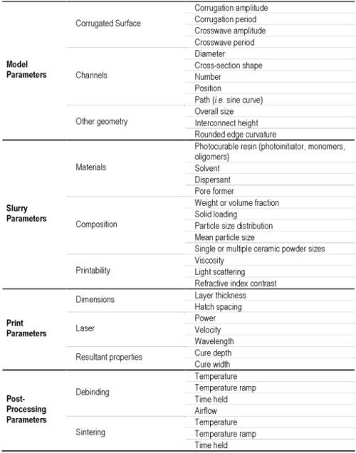
Table 1. Important properties to consider during each step of the process.
The student on this project analyzed the project and developed a personal plan for accomplishing the science of this research project. Four personal objectives to accomplish this goal are identified below. This is an iterative process, where previous steps may need to be revisited once knowledge is gained.
(1) Familiarize yourself with lab equipment, materials, and available resources. Understand how to operate equipment, and the capabilities / limitations of equipment specific to the lab, primarily including the DLP printer, ball mill, tube furnace and sintering furnace. Discuss with the PI and other lab members, read user manuals and informational documents. Discern the specific properties of materials available in the lab, including 8YSZ, photocurable resin, and any necessary additives such as solvents, dispersants or pore formers, learn safety and general lab procedures to feel comfortable working independently and consider computational analysis tools, such as the COMSOL fuel cell module.***
(2) Prepare a printable 8YSZ resin slurry. Formulate a detailed recipe, perform research and determine any knowledge gaps and predict any challenges or uncertainties in the process. After approval of the resin slurry recipe by the PI, prepare in lab, record all procedures and results and consider if any further testing for slurry properties is necessary.
(3) Print and post-process 8YSZ resin slurry. Determine all necessary print, debinding and sintering details via personal research. Prepare final CAD model, considering the printing of multiple designs of the 8YSZ anode on a single build plate and converting Stereo Lithography (STL) files using a slicer. Print the slurry in the DLP printer, considering the quality of the green body print and recording all procedures and results. Finally, clean, debind and sinter the green body, considering the quality of the sintered part, observing any cracking, and recording all procedures and results.
(4) Analyze and test the final product. Determine the relevant material properties and standard testing procedures, with a focus on SOFC applications. Classifications may include microstructure (porosity, pore size, grain size distribution), thermal and mechanical durability (mass loss in heating, energy absorbed when heating or cooling, strength, fracture toughness), electrochemical properties (ionic conductivity, activation energy).
4. Additional project details
4.1 Requirements for the 8YSZ anode CAD model
Create a 3D CAD model of a DLP printable 8YSZ anode, improving electrolyte and fuel channel contact area relative to the anode supported “flat-tubular SOFC” design.
The CAD model must have an electrolyte contact surface, interconnect contact surface, and lengthwise internal fuel channels. The dimensions should be approximately 15 mm x 50 mm x 3 mm (width x length x height).
The active surface area for both the electrolyte contact surface and fuel channels must be increased relative to a flat surface. The electrolyte contact surface should use oscillatory corrugations to increase relative surface area and fuel channels should use non-cylindrical paths to increase relative surface area.
The geometry and dimensions of the model must be manufacturable, using ceramic additive manufacturing (AM). The design must be printable using an 8YSZ slurry in a DLP printer and must survive post-processing and sintering without cracks. The cross-sectional wall thickness should be approximately 1 mm throughout. Finally, the CAD model should have round edges, avoiding sharp edges and corners.
The CAD model should be stable in design, allowing for dimensions and features to be edited without issue. Major dimensions should be input as Creo software parameters. All other model features should be related to parameters using Creo relations or workspace constraints.
The relative surface area increase should be simple to determine. The electrolyte and fuel channel surfaces should use sine curves as the basis for increased surface area. The entire electrolyte and fuel channel surfaces should be expressible by an equation, according to the following discussion.
4.2 Equation for the electrolyte contact surface
Relative increase in electrolyte surface area contact is achieved using two sine curves. A flat x-y plane can be transformed using a sine curve in the x-z plane, where z is a function of x. This creates peaks and troughs of the surface and is therefore referred to as the “corrugation” curve. The surface area of the corrugated surface may further be increased using a sine curve in the x-y plane, where x is a function of y. This creates the wave along the length of the peaks and troughs, and therefore is referred to as the “crosswave” curve.
This creates a pattern of wavy corrugations, as depicted in Fig. 1, which is modelled with a general parametric surface given in Equation (1). This equation relates height position (z-axis) as a function of width position (x-axis) and length position (y-axis). Ax and Ay express the amplitude of the corrugation and crosswave sine curves, respectively, while Tx and Ty express the periodicity of the corrugation and crosswave sine curves, respectively.
(1)

Figure 1 - Parametric surface of equation (1) (left) and bounded region of corrugation period by crosswave period (right).
The surface equation is especially useful as a tool for numerical calculation of relative surface area. The double integral in Equation (2) gives the general formula for surface area in any flat rectangular region on the x-y plane. Finding relative surface area increase is then simplified in Equation (3) by recognizing the repeating nature of the wavy corrugation pattern, where surface area in the region bounded by x = [0,Tx / 2π] and y = [0,Ty / 2π ] represents one full period of the corrugation and crosswave curve. Assuming the full surface has a length and width that is modular of their respective sine curve periods, the relative surface area increase of the whole region is the same as the relative surface area increase for any other modular region.
dx dy (2)
(3)
4.3 Design parameters and dimensions of 8YSZ CAD model
The CAD model incorporates the above surface by sweeping the corrugation curve along the crosswave curve, maintaining constant normal direction. The channels are also swept along the same crosswave curve and are centered at each peak of the electrolyte contact surface. All dimensions of the model were defined with customization in mind. Figure 2 illustrates a change in model parameters. Figure 3 shows the latest iteration of this model after updating and improving problem definition.
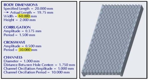
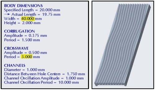
Figure 2 - Changing the width and crosswave period parameters in the model workspace.
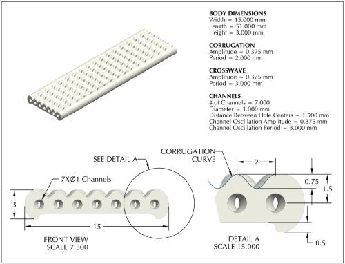
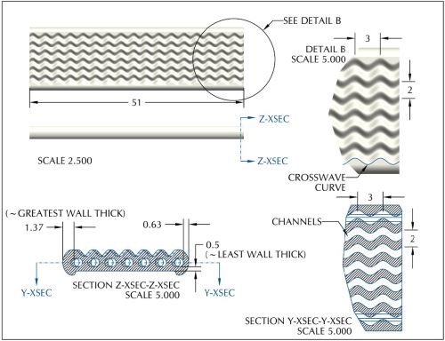
Figure 3 - CAD drawing with improved design of 8YSZ anode.
4.4 Approximated surface area as a function of design parameters.
Table 2 lists various possible configurations of surface parameters (amplitude and period of corrugation and crosswave curves) alongside the resultant relative surface area (SA) increase. Surface area was measured directly in the Creo Parametric model space after editing and regenerating the model, then divided by the SA of a similar size flat surface (same width x length) to produce approximate results of the relative SA increase. The first row of results uses the dimensions shown in Fig. 3, while subsequent rows contain highlighted values to indicate a change from the first-row reference.

Table 2 - Example parameter configurations and their relative SA increase.
5. Past project reports
1. Quarter 1 (January-March 2022): Summary: NASF Report in Products Finishing; NASF Surface Technology White Papers, 86 (10), 17 (July 2022); Full paper: http://short.pfonline.com/NASF22Jul1 .
2. Quarter 2 (April-June 2022): Summary: NASF Report in Products Finishing; NASF Surface Technology White Papers, 87 (1), 17 (October 2022); Full paper: http://short.pfonline.com/NASF22Oct2 .
3. Quarter 3 (July-September 2022) Part I: Summary: NASF Report in Products Finishing; NASF Surface Technology White Papers, 87 (3), 17 (December 2022); Full paper: http://short.pfonline.com/NASF22Dec2.
4. Quarter 3 (July-September 2022) Part II: Summary: NASF Report in Products Finishing; NASF Surface Technology White Papers, 87 (4), 17 (January 2023); Full paper: http://short.pfonline.com/NASF23Jan1.
6. About the Principal Investigator for AESF Research Project #R-123

Majid Minary Jolandan is Associate Professor of Mechanical Engineering at The University of Texas at Dallas, in Richardson, Texas, in the Erik Jonsson School of Engineering. His education includes B.S. Sharif University of Technology, Iran (1999-2003), M.S. University of Virginia (2003-2005), Ph.D. University of Illinois at Urbana-Champaign (2006-2010) as well as Postdoctoral fellow, Northwestern University (2010-2012). From 2012-2021, he held various academic positions at The University of Texas at Dallas (UTD) and joined the Faculty at Arizona State University in August 2021. In September 2022, he returned to UTD as Associate Professor of Mechanical Engineering. His research interests include additive manufacturing, advanced manufacturing and materials processing.
Early in his career, he received the Young Investigator Research Program grant from the Air Force Office of Scientific Research to design high-performance materials inspired by bone that can reinforce itself under high stress. This critical research can be used for aircraft and other defense applications, but also elucidates the understanding of bone diseases like osteoporosis.
In 2016, he earned the Junior Faculty Research Award as an Assistant Professor at the University of Texas-Dallas – Erik Jonsson School of Engineering.
* Corresponding author:
Dr. Majid Minary Jolandan
Department of Mechanical Engineering
The University of Texas at Dallas
800 West Campbell Road
Richardson, TX 75080-3021
Office: ECSW 4.355H
Phone: (972) 883-4661
Email: majid.minary@utdallas.edu
** Creo Parametric, PTC Inc., Boston, MA
*** COMSOL - Software for Multiphysics Simulation, COMSOL, Inc., Burlington, MA.
Related Content
NASF/AESF Foundation Research Project #123: Electrochemical Manufacturing for Energy Applications – 8th Quarterly Report
The NASF-AESF Foundation Research Board selected a project on electrodeposition toward developing low-cost and scalable manufacturing processes for hydrogen fuel cells and electrolysis cells for clean transportation and distributed power applications. This report covers the 8th quarter of work (October-December 2023, continuing work on 3D printing anode support for solid oxide fuel cells and electrolyzers. Work involved the effect of sintering temperature on the amount of porosity and grain size in 3D printed yttria-stabilized zirconia (YSZ).
Read MorePossibilities From Electroplating 3D Printed Plastic Parts
Adding layers of nickel or copper to 3D printed polymer can impart desired properties such as electrical conductivity, EMI shielding, abrasion resistance and improved strength — approaching and even exceeding 3D printed metal, according to RePliForm.
Read MoreNASF Foundation Research Project #123: Electrochemical Manufacturing for Energy Applications - 10th Quarterly Report
The NASF-AESF Foundation Research Board selected a project on electrodeposition toward developing low-cost and scalable manufacturing processes for hydrogen fuel cells and electrolysis cells for clean transportation and distributed power applications. In this period, we followed our work on 3D printing anode support for solid oxide fuel cells, focusing on the thermal shock properties of 3D printed yttria-stabilized zirconia (YSZ).
Read MoreNASF/AESF Foundation Research Project #123: Electrochemical Manufacturing for Energy Applications - 9th Quarterly Report
This NASF-AESF Foundation research project report covers the ninth quarter of project work (January-March 2024) at the University of Texas at Dallas. In this period, we followed our work on 3D printing anode support for solid oxide fuel cells, SOFC (or cathode for solid oxide electrolyzers, SOEC). We focused on the mechanical properties of 3D printed yttria-stabilized zirconia (YSZ) using a four-point bending test. We then conducted a statistical analysis to characterize the flexural strength of porous 3D printed YSZ. The full paper on the ninth quarter work can be accessed and printed at short.pfonline.com/NASF24June2.
Read MoreRead Next
Delivering Increased Benefits to Greenhouse Films
Baystar's Borstar technology is helping customers deliver better, more reliable production methods to greenhouse agriculture.
Read MoreEpisode 45: An Interview with Chandler Mancuso, MacDermid Envio Solutions
Chandler Mancuso, technical director with MacDermid Envio discusses updating your wastewater treatment system and implementing materials recycling solutions to increase efficiencies, control costs and reduce environmental impact.
Read MoreA ‘Clean’ Agenda Offers Unique Presentations in Chicago
The 2024 Parts Cleaning Conference, co-located with the International Manufacturing Technology Show, includes presentations by several speakers who are new to the conference and topics that have not been covered in past editions of this event.
Read More






.jpg;maxWidth=300;quality=90)

