OEM Testing Matrix Review with Trivalent Chromium
Continued tightening of regulations on hexavalent chromium used in decorative plating have caused an increased interest from OEMs in the performance of trivalent chromium plating regarding extended outdoor corrosion and accelerated corrosion performance tests. This article reports on corrosion testing results of trivalent chromium deposits with various thickness levels of chromium and various STEP values of the underlying nickel deposits.
A Paper* based on a Presentation given at SUR/FIN 2019 (Rosemont, Illinois)
by
Mark Schario**
Columbia Chemical Corporation
Brunswick, Ohio, USA
Editor’s Note: The following is a paper based on a presentation given at NASF SUR/FIN 2019, in Rosemont, Illinois on June 3, 2019 in Session 1, Automotive 1: Innovative Decorative Finishes. A pdf of this brief can be accessed and printed HERE; the complete Powerpoint presentation is available by clicking HERE.
ABSTRACT
Continued tightening of regulations on hexavalent chromium used in decorative plating have caused an increased interest from original equipment manufacturers (OEMs) in the performance of trivalent chromium plating with regards to extended outdoor corrosion as well as accelerated corrosion performance tests. This presentation reports on corrosion testing results of trivalent chromium deposits with various thickness levels of chromium and various STEP values of the underlying nickel deposits.
Introduction
Among the various original equipment manufacturers (OEMs), there has been an overall curiosity about how trivalent chromium performs versus hexavalent chromium in corrosion tests with different chromium thicknesses and with different STEP† values in the underlying nickel. This paper reviews those results. All test results are from a trivalent chromium-mixed sulfate/chloride electrolyte versus a dual catalyst hexavalent chromium (fluoride/sulfate) electrolyte.
Basis for the test matrix
Trivalent chromium is microporous at low thicknesses, and micro-discontinuous (i.e., microporous or microcracked) at high thicknesses. In contrast to hexavalent chromium deposition, trivalent chromium needs no particles in the underlying nickel layer to achieve porosity. However, too high a thickness can lead to microcracking. The OEM request was to identify the thickness effect on performance, given the structural difference over the thickness range.
With trivalent chromium, corrosion resistance is enhanced by a STEP potential between the bright nickel and the low sulfur strike. The proper STEP value prevents undercutting of the trivalent chromium deposit. In this regard, the OEM request related to identifying the effect and the range for best performance.
OEM test matrix - Phase 1
The objectives of the Phase 1 test matrix were threefold:
- Evaluate trivalent chromium versus hexavalent chromium at 40 mV.
- Evaluate trivalent chromium at three different thickness values, 0.15, 0.3 and 0.5 microns over microporous nickel (extremely high porosity).
- Evaluate hexavalent chromium over a low sulfur nickel strike (LSS) with extremely low porosity, for reference.
The test matrix variables, as noted above, were the chromium thickness and STEP potential measurements. The change in character of trivalent chromium from microporous at low thickness to micro-discontinuous at higher thickness suggests that the corrosion performance would be affected by the transition. Hence, there was a need to identify the thickness effect on performance.
STEP testing
The STEP Test, developed by Harbulak in 1980,1,2 measures the potential difference between the nickel plating layers, in a decorative multilayer system, e.g., between semi-bright and bright nickel layers in a dual nickel system. Measured and reported in millivolts (mV), the values can be either positive or negative. The importance lies in whether the nickel layer is cathodic or anodic with respect to the reference layer. More active layers will preferentially corrode as compared to more noble layers.
Figure 1 relates the STEP test to a modern four-layer nickel system. The photo compliments the schematic at the left. Starting at the copper substrate and working up, there is a semibright nickel layer, a high sulfur layer, a bright nickel layer, a microporous layer (or low sulfur strike) and finally a thin chromium layer (too thin to be visible). The photo shows a small corrosion area on the top with the corrosion proceeding through the bright nickel layer and then spreading out horizontally at the high sulfur layer. The system is designed to control the corrosion to provide a visually defect-free coating after extended corrosion.
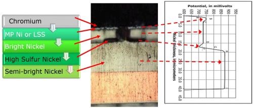
Figure 1 - Configuration of a four-layer nickel system and its relation to an ideal STEP potential curve.
The graph at the right shows an ideal STEP curve for the four-layer nickel system. The zero point on the x-axis corresponds to the copper-nickel interface. Working upward the bottom dashed arrow points to (1) the semi-bright Ni potential (line H-I), (2) the thin high sulfur nickel potential (point E), (3) the bright nickel potential (line CD) and (4) the microporous nickel (point B). In these tests, the STEP values for Phase 1 testing were maintained at:
- Semibright to bright 110-130 mV difference
- High sulfur to bright 20 - 40 mV difference
- Microporous to bright 30 - 50 mV difference
Corrosion testing
Evaluation of corrosion performance is based on (1) the number of active sites (i.e., porosity) observed after 88 hr of CASS3 or Porosity testing and (2) 336 hr of the ASTM-B-995 Russian Mud Test.4 Figure 2 shows the types of active sites encountered in the Phase 1 corrosion testing after 88 hr of CASS exposure. Low porosity (at left) will concentrate the corrosion current in a few areas, causing deep wide corrosion pits visible to the eye after extended outdoor exposure. “Normal” porosity, between the two extremes shown, will spread out corrosion to many small areas, making the corrosion invisible to the eye. High porosity (at right) can make corrosion areas so frequent and small that it can become visible to the eye as a haze.
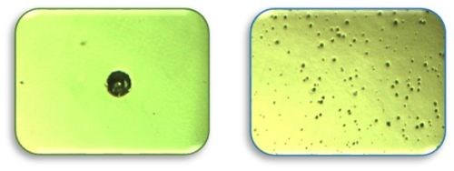
Figure 2 - Types of porosity encountered in Phase 1 CASS testing.
Phase 1 test results
The ratings of the Phase 1 test panels after 88 hr of CASS testing are shown in Fig. 3. From left to right, the first column shows the nickel type directly under the chromium, whether it is a microporous nickel to provide the STEP potential and porosity from particles in the nickel or a low sulfur strike to simply provide an appropriate STEP value. The next column shows the STEP value in mV, followed by the thickness of the chromium in μm. Next is the type of chromium whether hexavalent (HEX) or trivalent (TVC). The last two columns show the panel ratings, 1-10, for visible haze and surface pits.
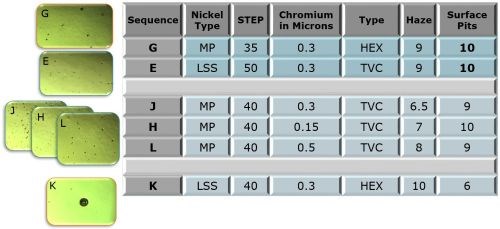
Figure 3 - Phase 1 test panel ratings after 88 hr of CASS testing.
Figure 4 shows the ratings of the panels after 336 hours of Russian mud testing. The configuration of the table is similar to that for the CASS testing.
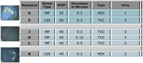
Figure 4 - Phase 1 test panel ratings after 336 hr of Russian mud testing.
Phase 1 discussion
The corrosion protection provided by the decorative chromium overlay operates somewhat differently, when the hexavalent and trivalent chromium are compared. In the hexavalent case (Fig. 5(a), the chromium provides hard passive layer and white color. The microporous nickel provides porosity and prevents undercutting of the chromium layer. The sulfur-containing bright nickel acts as the sacrificial layer. The high-sulfur nickel is anodic to the bright and semi-bright layer, while the semi-bright nickel layer prevents corrosion to the substrate.
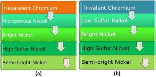
Figure 5 - Comparison of (a) hexavalent and (b) trivalent chromium overlays on four-layer nickel.
Considering the trivalent chromium case (Fig. 5 (b), every layer from the copper up to the bright nickel is the same as the hexavalent chromium system. But the layer above the bright nickel is commonly called “low sulfur nickel.” Its name is different because there is no need for particles to induce porosity when using trivalent chromium. The trivalent chromium provides hard passive layer and white color, as does hexavalent chromium, but also is microporous as plated.
The obvious operational advantage of using trivalent chromium is the fact that that the porosity is uniform over the entire surface. There is no need to shut down the line to treat the nickel (remove the particles) and no fear of reduced porosity from high chromium thickness.
A comparison of the active sites produced after 88-hr CASS for the systems shown in Fig. 5 is shown in Fig. 6. Here, 0.3 μm of trivalent chromium over low sulfur nickel is compared with 0.3 μm of hexavalent chromium over microporous nickel, corresponding to the data of samples E and G referenced in Fig. 3, respectively.
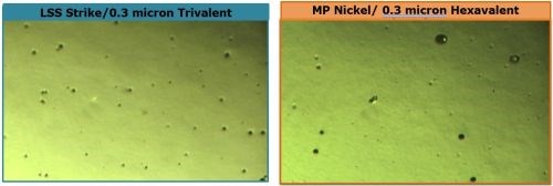
Figure 6 - Comparison of active sites after 88-hr CASS for (a) trivalent and (b) hexavalent chromium over nickel.
The trivalent result (L) shows a relatively uniform dispersal of active corrosion sites, with a narrow range of pore diameters, suggesting the corrosion current is well distributed. On the other hand, fewer sites are seen for the hexavalent result (R), with a wider range of pore diameters. The corrosion current distribution is less uniform and, in some cases, the active sites were large enough to produce heavier local nickel attack. Nonetheless, the CASS corrosion ratings for both samples (Fig. 3, E and G) were good. Analysis of the 336-hr Russian mud data for chloride resistance from Fig. 4 for conditions E and G shows that the trivalent system (Rating = 3) performed better than the hexavalent (Rating = 1).
Referring again to the 88-hr CASS data in Fig. 3, three trivalent chromium samples with increasing thicknesses, 0.15, 0.30 and 0.50 μm (H, J, and L, resp.) are shown. In this case however, the top nickel layer was the microporous nickel usually used with hexavalent chromium. This creates very high porosity in the chromium layer. The low haze ratings in the data reflect this result. The corresponding Russian mud rating did not change with thickness (Fig. 4, H, J and L).

Figure 7 - Comparison of active sites after 88-hr CASS for trivalent chromium over microporous nickel, yielding high as-deposited porosity. Porosity tends to decrease with increasing thickness (L to R).
Conversely, plating hexavalent chromium over a low sulfur nickel deposit tends to create very low porosity. The surface pit rating (Fig. 3, K) reflects this. The 88-hr CASS result in Fig. 8 is a striking example of the localized corrosion current attack developed in this case.
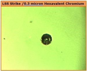
Figure 8 - Pit development after 88-hr CASS with a hexavalent chromium deposit over LSS nickel with very low porosity.
Future work
Additional work planned with the OEM Test Matrix is shown in Fig. 9 with emphasis on 48-hr CASS results, as well as additional Russian mud testing. The trivalent chromium-low sulfur nickel work will focus on varying the step potential and trivalent chromium thickness.
Work on the horizon will include a similar test matrix with black trivalent chromium, and test matrixes involving functional deposits, including (1) zinc-nickel with a black passivate and sealer and (b ) zinc-nickel for ductility.
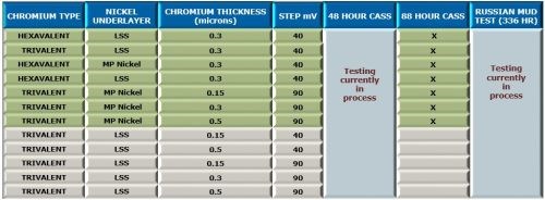
Figure 9 - Future work planned with trivalent chromium systems.
About the author

Mark Schario is Executive Vice-President at Columbia Chemical Corporation, headquartered in Brunswick, Ohio. He joined Columbia Chemical in 2010 as Vice President, Technologies and now serves as Vice President, Global Business Development for the company. He has over 30 years of experience in the surface finishing industry. Mark also functions as the company’s top liaison to the automotive industry and is involved with the ASTM B08 Committee on Metallic and Inorganic Coatings which has jurisdiction over 132 standards. He is a member of the NASF and has earned the industry designation of CEF/Certified Electroplater-Finisher. Mark holds an Executive MBA from the Weatherhead School of Management at Case Western Reserve University.
*Compiled by Dr. James H. Lindsay, Technical Editor - NASF
** Corresponding author:
|
Mark Schario Executive Vice President Columbia Chemical Corporation 1000 Western Drive Brunswick, OH 44212 Phone: 440-840-7166 Email: mark.schario@columbiachemical.com |
† Simultaneous Thickness and Electrochemical Potential (STEP) test, measuring the potential between layers of a multilayer nickel plating system.
1 E.P. Harbulak, “Simultaneous Thickness and Electrochemical Potential Determination of Individual Layers in Multilayer Nickel Deposits,” Plating and Surface Finishing, 67 (2), 49-54 (1980); a 2016 re-publication is available at http://short.pfonline.com/NASF16Feb1.
2 ASTM B764-04(2014), Standard Test Method for Simultaneous Thickness and Electrode Potential Determination of Individual Layers in Multilayer Nickel Deposit (STEP Test), ASTM International, West Conshohocken, PA, 2014, www.astm.org.
3 ASTM B368-09(2014), Standard Test Method for Copper-Accelerated Acetic Acid-Salt Spray (Fog) Testing (CASS Test), ASTM International, West Conshohocken, PA, 2014, www.astm.org.
4 ASTM B995-15a, Standard Test Method for Chloride Resistance Test for Chromium Electroplated Parts (Russian Mud Test), ASTM International, West Conshohocken, PA, 2015, www.astm.org.
Related Content
NASF's SUR/FIN 2023: Bringing the Surface Finishing Industry Together
SUR/FIN 2023 is an opportunity for those in the surface finishing industry to expand their knowledge, expertise and network.
Read MoreSUR/FIN 2023: Capsules from the Technical Sessions I: Emerging Technologies
SUR/FIN 2023 in Cleveland this past June was a resounding success. Due to the efforts of the Technical Activities Committee, ably led by Bill Nebiolo this year, an outstanding program of technical presentations was offered. What follows are summaries of selected presentations from the Emerging Technologies sessions. Additional coverage will be provided in this space in the coming months. The full report can be accessed and printed at short.pfonline.com/NASF23Aug1.
Read MoreElectroplating in the Context of Worldwide Nanotechnology Initiatives: A Heritage Paper
In the first part, a summary is presented on recently established nanotechnology initiatives in various countries around the world. Program funding levels and core activities will be compared to provide a basis for assessing business opportunities for various industries. The second part of the paper looks at specific examples of nanostructures made by electrochemical methods currently at various stages in their development, or already in use.
Read MoreTin-Zinc Alloy Electroplating and Its Corrosion Behavior
An NASF/AESF Foundation Research Program Retrospective
Read MoreRead Next
Episode 45: An Interview with Chandler Mancuso, MacDermid Envio Solutions
Chandler Mancuso, technical director with MacDermid Envio discusses updating your wastewater treatment system and implementing materials recycling solutions to increase efficiencies, control costs and reduce environmental impact.
Read MoreA ‘Clean’ Agenda Offers Unique Presentations in Chicago
The 2024 Parts Cleaning Conference, co-located with the International Manufacturing Technology Show, includes presentations by several speakers who are new to the conference and topics that have not been covered in past editions of this event.
Read MoreEducation Bringing Cleaning to Machining
Debuting new speakers and cleaning technology content during this half-day workshop co-located with IMTS 2024.
Read More


