Recycling Aqueous Cleaning Solutions
Using membrane filtration to recycle aqueous cleaning solutions...
During this century, industrial technology and capacity has grown tremendously. Demand for goods created an economy that favored resource-intensive industries. However, natural resource consumption and subsequent discharges to the air, water and land were enormous and often made without consideration of environmental consequences.
By mid-century, landfilling and deteriorating air and water quality became a national priority, leading to the creation of the U.S. EPA. An early action of EPA was the Clean Water Act of 1972. It authorized a comprehensive federal water pollution control system to reduce discharges into the nation's surface waters and restore and maintain the chemical, physical and biological integrity of the water. The ultimate goal was to make the waterways suitable for fishing, swimming and recreation.
By the late 70s and early 80s, effluent guidelines had been set for most industry sectors that discharged toxic organics, heavy metals, cyanide and oil and grease. The metal finishing effluent guidelines of 1983 (40 CFR part 433) sets limits on discharged pollutants. Industries covered include electroplating, electroless plating, anodizing, coating (chromating, phosphating and coloring), chemical etching and milling and PCB manufacturing.
If a facility engages in any of these processes, then discharges from other regulated operations in that facility are also subject to the guidelines. These 40 other unit operations include metal working, organic coating and paint stripping, among others. Permitting authorities use these guidelines as a basis for permitting and setting limits on heavy metals, grease and oil and total toxic organics. Federal law requires that limits be at least as stringent as the U.S. EPA guidelines.
Because of these regulations, most industries installed waste treatment systems.
The typical technology is a pH adjustment and oil skimming followed by a lime and settle treatment. The treated water is discharged, and the precipitated waste is compacted in a filter press. The lime and coagulants used in this process add considerable bulk to the landfilled waste.
Many manufacturing operations, however, have effluent from metal working processes and are not subject to EPA guidelines. For example, a machine shop that discharges effluent from an aqueous degreasing system and does not engage in one of the six trigger categories is not covered by the guideline.
Because of this, a newer rule with broader coverage is under development. The Metal Products and Machinery Rule covers facilities by sector, similar to the scheme used for SIC codes, rather than by specific processes. According to the EPA website, this rule is scheduled for signature in October 2000. Under this rule, effluent volume will be considered as well as discharge quality. Using these metrics, the facility may have mass-based limits that are calculated by the pollutant concentration multiplied by the volume of the discharge per unit time. Facilities that institute water-conserving practices that increase the concentration of a pollutant will not be penalized by regulation of the mass of pollutant discharge.
The Common Sense Initiative is a sector-based initiative intended to explore industry-specific environmental strategies. The program is designed to promote cleaner, cheaper and smarter environmental performance using a non-adversarial process that tests new ideas and approaches.
The Metal Finishing sector includes representatives from EPA, the industry, state government, POTWs, environmental organizations and organized labor. The Strategic Goals Program arose from this initiative. This creates two voluntary cleaner, cheaper, smarter national performance goals for the industry. The first goal is facility-based, and the other is an industry-based goal. One goal addresses water use. Using 1992 as a base year, the facility-based goal is to achieve a 50% reduction in water purchased and used by 2002. The industry goal is for 80% of facilities nationwide to achieve these goals.
The Metal Products and Machinery Rule and trends toward voluntary initiatives are helping the nation's industries achieve the zero discharge goal of the Clean Water Act of 1972. Membrane filtration technologies are increasingly recognized as ways of achieving the goals.
Basic concepts and terminology
Several terms describe an ultrafiltration/microfiltration system.
- Crossflow.
- Flow of solution parallel or tangential to the membrane surface. Counteracts concentration polarization.
- Feed.
- Starting solution to be processed.
- Flux.
- Measure of membrane productivity in liters of permeate or filtrate produced in one hour by one sq meter of membrane area.
- Fouling.
- Interaction between substances in the feed and the membrane that reduce flux. Usually reversible.
- Permeate (filtrate).
- Solution that permeates or passes through the filter.
- Plugging.
- Accumulation of particulates in the membrane passages that restrict flow.
- Pores.
- Filter passages for solution.
- Retentate/concentrate.
- Residual solution containing the concentrated contaminants.
- Rejection.
- Filter's ability to retain contaminants. A 100% rejection indicates complete retention. In the context of aqueous cleaner recycling, a 100% rejection of the contaminants is desirable.
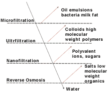
UF/MF is a pressure-driven separation process. It uses a semi-permeable barrier (membrane) to separate feed-stream components according to particle size. Feed stream components that have a particle size larger than the pore sizes of the membrane are retained while smaller one pass through. Ultrafiltration is an extension of conventional filtration, which is considered appropriate for filtration of particles larger than 5mm. The term microfiltration usually applies to filters that separate particles in the size range of 0.05mm to 5mm. Ultrafiltration separates both particulate matter as well as dissolved substances in the range of 0.001mm to 0.1mm. The distinction between the two is blurred in the range of 0.03mm to 0.1mm. Membranes used to regenerate aqueous cleaners have pore sizes ranging from 0.05mm to 0.45mm. The terms ultrafiltration and microfiltration are interchangeable in this article.
A major difference between conventional and membrane filtration is the mechanism of particle capture. Conventional filters capture particles in a matrix that cannot be regenerated. Membrane filters are usually sized to have pores that are too small for particles to enter, so the bulk of filtration occurs at the filter surface. Membrane filters can be reused after flushing or cleaning.
Crossflow filtration describes the flow of feed solution in a direction parallel to the membrane or filter surface. This "sweeps" the membrane surface and limits filter cake buildup, allowing for longer operating times. A small portion of solution is forced through the membrane by the applied pressure and is recovered as permeate.
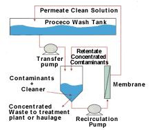
During ultrafiltration dirty cleaner solution is pumped from the wash tank into a holding (process) tank. A pump constantly circulates the solution from the process tank across the membrane surface. A valve at the exit of the membrane controls pressure. Part of the dirty cleaner solution is forced through the membrane while dirt and other contaminants are rejected at the membrane surface and returned to the process tank. Recovered clean permeate is returned to the wash tank. A level controller in the process tank allows for additional solution transfer from the wash tank to the process tank. Eventually, the wash tank's entire contents are filtered and replaced with clean permeate. Dirt and other contaminants would have been transferred from the wash tank to the process tank where they are concentrated. Usually, after turning over many wash tank volumes, the increase in contaminant concentration would have reduced the permeate flux to below design levels. Cleaning the filters restores the permeate flux. After cleaning, the membrane can be used again. Concentrated contaminants are either treated or disposed of accordingly.
Aqueous cleaners typically contain alkaline/acidic salts; sequestering/chelating agents; wetting/emulsifying agents (surfactants); and co-solvents. Each component has a specific role in the cleaning process.
Alkaline salts neutralize acidic soils/contaminants. An example would be the neutralization of free fatty acids to form soaps. Some alkaline salts, such as sodium silicates and phosphates, perform additional functions. Silicates are used in cleaners because silicic acid has significant soil dispersing capabilities and prevents soil redeposition. Other benefits include inhibition of alkaline attack on aluminum and prevention of rust on steel. Sodium and potassium phosphates have some detergency, especially in the case of mineral ions. They also promote efficient cleaning by binding ions that cause hardness in water.
Salts, such as calcium and iron, can form deposits on parts left in solution. Chelating agents are specially formulated to bind these ions. The type used depends on its effectiveness at a given pH, temperature and complex stabilization capability for targeted ions. Sodium gluconate, for example, is partially effective at binding calcium, but very effective at binding iron under alkaline conditions.
Surfactant molecules are made up of a hydrophilic (water-loving) and a hydrophobic (water-repelling) part. Surfactants help remove oil and stabilize the removed oil, preventing it from redepositing on the part. There are anionic and nonionic surfactants. Anionic surfactants include the linear alkylarylsulfonates, phosphate esters and alcohol sulfates. Common nonionics include alkylphenolethoxylates, linear and secondary alcoholethoxylites and ethlyeneoxide-propyleneoxide copolymers. In general, anionics are used as wetting agents, and nonionics are used for emulsifying oils and controlling foam.
Organic co-solvents may also be part of the formulation. These lower the surface tension of the cleaner, promoting solubility of surfactants and stabilizing oil emulsions.
Limiting an Aqueous Cleaner's Useful Life
Under normal conditions, cleaning solutions pick up contaminants. Oil and grease in an emulsified form consume surfactants, eventually compromising detergent and emulsification action. The cleaner should show signs of aging long before surfactant depletion becomes important.
With aqueous cleaners, the alkalinity of the bath decreases with use because the alkaline salts are neutralized with acidic soils or by reaction with carbon dioxide from air. Metal accumulation may overcome the sequestering agents, preventing them from staying in solution. Subsequently, they bind to the ionic surfactants leading to a loss of wetting properties.
The most important factor in determining the useful life of an aqueous cleaner is its ability to prevent redeposition, particularly as contamination increases. This is the major limiting factor in extending cleaning bath life. It is here that membrane filtration plays a critical role, allowing for the selective removal of contaminants and prolonging cleaner life.
Regeneration
Successfully implementing an ultrafiltration system for regenerating aqueous cleaners requires careful consideration of the cleaner; compatible membrane materials; correct filter sizing; effective membrane cleaning; and makeup schedules for depleted active components.
Characteristics such as pH, nature of alkaline components, cloud point, temperature and the presence of certain compounds such as limonene, are important considerations when selecting a filter. An understanding of these characteristics also helps evaluate potential recyclability and problems that may occur during recycling.
Alkaline cleaners vary in strength, and the pH is often greater than 9. As pH increases above 12, the cleaning solutions become aggressive and react with membrane materials, leading to degradation and filter failure. As an example, the presence of silicates under certain conditions causes precipitation of silicic acid on the membrane surfaces leading to drops in permeate flux. Understanding the cleaner constituents can help avoid conditions not conducive to membrane filtration.
The cloud point refers to the appearance of turbidity with an increase in temperature. It is caused by increased insolubility and separation of the nonionic surfactant(s) from the solution. Above the cloud point, the nonionic surfactants are similar to oils in solution; therefore, high losses during filtration can be expected. Aqueous cleaner cloud points vary. Those with cloud points above the ultrafiltration system's operating temperature are more readily recycled. Otherwise, cooling the cleaner solution below the cloud-point temperature may work to avoid surfactant loss. Most membrane materials made of organic polymers are also limited by their inability to withstand temperatures exceeding 140F. For ultrafiltration temperatures above 150F, inorganic membranes are used, although high-temperature polymeric-based membranes are also available.
Recently, limonene (derived from citrus fruits) and other related compounds have gained popularity in aqueous cleaning. These chemicals are not water-soluble; water stabilizes them. The resulting emulsion is the same size as the oil and grease contaminants, so they are removed during filtration. Even when present in trace quantities, however, they can interact with and foul membrane surfaces.
Membrane materials
Membrane materials for filtering aqueous solutions are broadly classified as organic polymer based or inorganic/ceramic. The inorganic membranes are usually made of alumina, zirconia or sintered steel.
These materials differ in their ability to withstand high temperatures and extreme pH. Organic membranes are generally limited to a pH less than 12 and operating temperature less than 140F. The temperature and pH limits of organic membranes are interdependent. Operating at the limits of both shortens membrane life. Inorganic membranes withstand the highest temperature (200F) and a pH up to 14.
Both membrane types vary in their ability to interact with the cleaner components. Water-repelling surfaces can be coated or fouled by hydrophobic compounds such as oil or grease. This coating can be reversible (cleaned off) or irreversible. If irreversible, there is a drop in membrane productivity. Membrane manufacturers can supply modified versions of the polymers with decreased susceptibility to fouling such as modified polyvinylidenedifluoride or polysulfones. Inorganic membranes are also susceptible to fouling; therefore, it is important to study the operating conditions of the filters as well as the compounds the filter contacts.
Pore size
The objective in cleaner regeneration is to separate the contaminants selectively while recycling the active ingredients. Oil, if present as an emulsion, typically has particle size distributions in excess of 0.1mm. In contrast, all the aqueous materials are completely dissolved and have sizes approximately 1/10,000th of 1mm. The surfactant molecules are the only active ingredients comparable in size to the oil emulsion. Although surfactant's molecules have low molecular weights, they can form large aggregates.
The nature of the surfactant, its concentration, operating temperature, electrolyte content and the presence of contaminants such as oil and grease are important to controlling surfactant aggregate size. The appropriate choice of the membrane pore size should allow the separation of the oil emulsion from the surfactant aggregate. The wrong choice can lead to unacceptable losses of surfactant and significant loss of cleaner efficiency. This is unique to membrane filtration.
Module configuration
Once an appropriate membrane material has been identified, the module configuration must be determined. The packing density of modules refers to the membrane area packed into a module of given volume. Modules with larger packing density offer space savings. Less obvious are the savings in pumping energy that result from the hydrodynamic regime in which these modules operate. For example, tubular membranes with low packing densities require high recirculation rates to maintain adequate turbulence. Hollow fibers or spiral wound membranes offer higher packing densities and lower recirculation rates. However, these often require prefiltration of the process fluids to avoid plugging the fluid passages.
Pressure capability is not critical
All modules are suitable because pressures less than 30 psig are normally used for ultrafiltration of alkaline cleaners. Fouling resistance, however, is important. Studies indicate that particulate fouling and free-oil fouling can be significant for the filtration of alkaline cleaners because the used cleaning solutions contain a lot of fine material and visible oil slicks. The particulates block membrane passages externally and internally. There are two ways of controlling this.
1. Appropriate filtration. A common rule is to prefilter to at least 1/10th the size of the fluid passageway. For example, hollow fiber modules using fibers of 250mm would need prefiltration to 25mm. This prefiltration level should be sufficient for alkaline cleaner recycling using spiral-wound membranes. Sometimes, prefiltration to 5mm is needed. Prefiltra-tion is not usually required with tubular membranes.
2. Low pressure and high shear rates at the membrane surface help prevent solids accumulation. Energy savings can also be achieved. Conventionally, high shear rates at the membrane's surface are generated by maintaining a high flow rate across the membrane surface, such as 30-45 gpm for one-inch tubular modules. Newer approaches use turbulent vortices created by a rotating surface near the membrane surface or produced by curved membrane passages, periodic backpulsing and mechanical vibration. Periodic backpulsing is available only for hollow fiber and ceramic tubular monolith modules. The vortex approach is available for membrane modules that use plate-and-frame configurations.
Free-oil fouling can be mitigated with an external coalescer to pretreat the feed. The membrane surface can also be altered by grafting hydrophilic groups to help prevent free-oil fouling. Another option is coalescence by adding salts.
The level of cleaning differs among modules
Tubular membranes can be mechanically cleaned and offer some access to the permeate-channel sides. Hollow-fiber modules can often be backflushed and offer good access to the permeate channels. Spiral-wound membranes are more susceptible to fouling and are more difficult to clean. Tubular monolith ceramic membrane modules can be backflushed and withstand harsh cleaning.
Membrane modules depend on the application, dirt and oil loading. For high particulate loadings, tubular membranes operating under a low pressure and high flow rate may be adequate. If the system is started under relatively low particulate loading conditions, a hollow fiber or spiral-wound membrane would be adequate with prefiltration. Backpulsing is recommended for hollow fiber and ceramic tubular modules. To avoid free-oil fouling, a hydrophilic membrane surface is needed or an external coalescer is essential.
Membrane cleaning. Membranes inevitably show a loss in flux because of increased contaminant concentration, salt precipitation and fouling. Loss of flux from increased contaminant concentrations is unavoidable, since it results from ultrafiltration. Normally, the membrane is cleaned when the flux has dropped to a certain level.
Fouling and salt precipitation also cause rapid flux decrease (minutes to hours). Careful membrane choice and feed pretreatment can control fouling and lower cleaning frequency.
Chemical additive management.Ultrafiltration of aqueous cleaners will lead to a loss of active cleaner components because of surfactant reaction with large oil emulsions. Plugged membrane pores can also retain surfactants, leading to loss. Alkalinity loss from air contact during pumping can occur. Such losses often lead to reduced efficiency unless chemicals are added to the cleaner.
Alkalinity is monitored and controlled in an industrial setting; however, surfactants are difficult to measure without sophisticated analytical equipment. Estimates of surfactant loss with a given membrane need to be generated prior to implementing the technology. Once this is determined, an additive package of surfactants can be formulated and used in the field without additional testing. A thorough evaluation of both aqueous cleaners and membrane materials will ensure recycling success. This includes screening the membrane materials for cleaner compatibility. Pilot scale testing with identified membranes follows bench-scale testing.
Case studies
A metal shelving manufacturer used a one-step degreasing/phosphating solution to prepare surfaces for painting. Dirt and oil buildup reduced cleaning and phosphating efficiency, compromising product quality. Residual oil and dirt affected adhesion and phosphate coating uniformity. Oil skimmers were only partially effective; the bath was replaced every three or four months. The spent bath was RCRA hazardous waste because it failed TCLP procedures for xylene. Disposal costs, including transportation and incineration, were approximately $1/gal, not including downtime, raw materials and energy costs.
Ultrafiltration was used to separate the oily contaminants and suspended solids. The recovered phosphating/degreasing solution was reused.
A hydrophilic form of polyvinyl-idenedifluoride (rated at 100,000 molecular weight cut-off) was chosen as the membrane material because in trials it was able to withstand acidic conditions. Tubular membranes were chosen because they withstood high-suspended solids loading and were easy to clean.
The cleaner's surfactant analysis revealed a substantial loss of nonylphenol ethoxylate surfactant and the ethoxylate alcohols were occurring. An additive package of surfactants was formulated and added to the bath regularly. This extended the bath life from a few months to more than five years.
Equipment capital costs were $12,000 with an estimated payback period of seven months.
Three years after the system was installed, the company experienced paint adhesion problems again. A site visit revealed an oil slick on top of the phosphating/degreasing bath that had not been observed after installation of the UF system. It turned out the chemical supplier had changed the formulation of the cleaner to enable low-temperature operation. The surfactant package used was only partially effective in emulsifying the oil, allowing the oil slick to develop. The problems here were directly related to the cleaner. Incorporating a stronger emulsifying package helped resolve the problem by keeping the oil suspended in solution and allowing subsequent removal using UF.
With careful testing during this long-term trial and development of a well-formulated solution maintenance program, the cleaning/phosphating solution can function for an extended time. The process is highly sensitive to the surfactants used; even minor formulation changes can cause problems with solution maintenance.
Alkaline cleaner recycling
At a railroad facility, UF was shown successful at extending an alkaline cleaner bath. The cleaner exhibited no cloud point, so temperature was not an issue. The cleaner's pH was about 10 and the operating temperature 180F. A polymeric membrane was used because of lower costs, but the feed temperature had to be cooled to 120F. The membrane was a hydrophilic PVDF in tubular form.
UF reduced cleaner concentrate consumption 73% and decreased effluent generation more than 99%. Capital equipment costs were recovered in two years.
The demonstration had its problems, however. The unit functioned well for one week before experiencing severe productivity loss. Cleaning the membrane did not help, since fouling reoccurred within hours. The fouling caused precipitates on the membrane surface and the permeate side. The cause was an organic calcium salt, presumably caused by an interaction between the defoamer and minerals in the water. Substituting soft water and adding EDTA to the retentate prevented further precipitation. Following this, the system's permeate flux was a constant 17 gph for 60 days.
The UF system successfully removed contaminants (oil, grease and TSS) and allowed complete passage of the organic solvent, surfactant and other active materials. This was a primary reason for a decrease in cleaner use.
Initially, water quality was the main cause for the system performing below par, emphasizing the importance of using softened water in UF. Also, softened water has elongated the time between membrane cleaning and lowered labor costs.
System specifications/operational considerations. Generally, a 0.1mm pore size membrane made of hydrophilic PVDF, polysulfone or polyacrylonitrile would be sufficient if the feed temperature was kept below 140F and pH less than 13. Otherwise, a ceramic membrane may be more appropriate. Ceramic membranes made of alumina are not appropriate for use with phosphoric acid solutions. Choosing a pore size is a compromise between fouling resistance, productivity and active component loss.
For high-suspended solids loading, a tubular or fat hollow fiber membranes are appropriate, as are flat sheet modules. For clean oil emulsions, the spiral format is usually more cost effective.
Membrane sizing is an important determinant of cost. The unit should be sized to turnover the cleaner solution in about half the time as the normal work life of the bath. Too frequent turnovers can increase capital and chemical maintenance costs.
A monitoring program for proper solution maintenance is necessary. The supplier is ideally positioned to help with this program and provide formulation information. Softened water is necessary to avoid membrane scaling.
UF for recycling aqueous cleaners has tremendous potential if investigated carefully, engineered properly and implemented conscientiously. As atechnology, it can reduce waste volumes and chemical consumption.
Related Content
Hexavalent to trivalent chromium — the environmental benefits
Regulatory pressures to switch from hexavalent chromium to trivalent alternatives are a growing concern for many finishing operations. In this Products Finishing Ask the Expert clinic, Brittany McKinney of Pavco discusses the environmental considerations driving these regulations.
Read MorePractical Environmental Management Reduces Costs, Refines Quality
By focusing on effluent treatment and efficient tin recovery, this Indian surface treatment plant meets stringent environmental standards and sustainable high-quality production.
Read MoreHow to Maximize Nickel Plating Performance
The advantages of boric acid-free nickel plating include allowing manufacturers who utilize nickel plating to keep up the ever-changing regulatory policies and support sustainability efforts.
Read MoreHeadquarters Relocates for Growth and Sustainability
Gema's headquarters moves to Gossau, Switzerland, to boost production capacity and sustainability efforts with upgraded testing labs and modern infrastructure.
Read MoreRead Next
A ‘Clean’ Agenda Offers Unique Presentations in Chicago
The 2024 Parts Cleaning Conference, co-located with the International Manufacturing Technology Show, includes presentations by several speakers who are new to the conference and topics that have not been covered in past editions of this event.
Read MoreEducation Bringing Cleaning to Machining
Debuting new speakers and cleaning technology content during this half-day workshop co-located with IMTS 2024.
Read MoreEpisode 45: An Interview with Chandler Mancuso, MacDermid Envio Solutions
Chandler Mancuso, technical director with MacDermid Envio discusses updating your wastewater treatment system and implementing materials recycling solutions to increase efficiencies, control costs and reduce environmental impact.
Read More











.jpg;maxWidth=300;quality=90)


