Sulfuric / Organic Electrolytes and Total Quality Improvement (TQI) for Present / Future Anodizing Requirements
After the last 12 years of developmental improvements and successful operation in production and selective brush anodizing, we present formulations for the new revised three-part organic acid blend. This ionic active blend detailed here can benefit all sulfuric anodize electrolytes to meet today's more demanding quality, specifications and production requirements.
by
Fred Charles Schaedel*
Anodic Technical Services
Westminster, California USA
Editor’s Note: Editor's Note: This paper is a peer-reviewed and edited version of a presentation delivered at NASF SUR/FIN 2016 in Las Vegas, Nevada on June 8, 2016. A printable PDF version of this paper is available for download by clicking HERE.
ABSTRACT
After the last 12 years of developmental improvements and successful operation in production and selective brush anodizing, we present formulations for the new revised three-part organic acid blend. This ionic active blend can benefit all sulfuric anodize electrolytes to meet today's more demanding quality, specifications and production requirements. This paper will discuss the following improvements: (1) surface protection of 2000/7000 series alloys during exposure to the sulfuric organic electrolyte, (2) pore structure development during the pulse-step-ramp cycle, (3) recurring problem solving situations and (4) a new in-tank test/control cell (including a data logger) that will allow the anodizer to prove how and why a 2 - 5% addition of this basic blend promotes total quality improvement (TQI) and efficiency for Type IC, II and III hard anodizing.
Background
Special sulfuric organic electrolytes as specified in Mil-A-8625, which are important for the anodize process, are actually sulfuric /carboxylic acids. Their importance is centered in the carboxyl (-COOH) group radical, which has been proven as an anodizing electrolyte and additive to the primary sulfuric electrolyte for the Type IC, II and III hard anodize processes.
For over 50 years, several organic carboxylic acids have been added in varying amounts to improve the sulfuric acid electrolyte. The basic and most inexpensive of them is oxalic acid, which became the basis for the Alumilite process. The Alumilite process is still used today in numerous commercial military and aerospace specifications. Also, the Martin hardcoat process finally went to oxalic Acid because it liberated carbon dioxide during the anodize process. Lactic and glycolic (hydroxyl acetic) acids became significant improvements because of the hydroxyl group, along with their availability and relatively low cost. This was the basis for the Reynolds multi-purpose anodize additive/electrolyte (MAE) developed under a NASA contract in the 1960s.
Citric acid is another significant carboxylic acid, which became part of very hard wear-resistant formulations. Numerous other carboxylic acids have been proven successful in enhancing the sulfuric acid electrolyte. However, many were rejected due to their costs and availability. Tartaric acid has been proven very successful in Type IC anodizing because it is a dihydroxy dicarboxylic acid (dihydroxy succinic acid). Through insights gained from endothermic heat absorption energy levels within the anodic pore structure, these acids used together as a “Complete Spectrum Approach” became very important in the quest for a blended concentrate over the past twelve years:
- Oxalic Acid
- Tartaric Acid
- Glycolic Acid
- Citric Acid
- Lactic Acid
- Benzoic Acids (Hydroxy)
The first mixed concentrates worked fairly well in production and were designated as AME in past technical papers. However, improvements were still needed for Type II, 23 and III anodize when operating as a universal electrolyte.
Introduction
This paper presents a review of the importance of organic carboxylic acids and sulfuric / organic mixed acid blends for improving the anodize process, both now and in the future. Certain basic carboxylic acids should be used for all sulfuric acid anodizing in order to meet today's more demanding quality, specifications and production requirements. Also, and more importantly, this paper presents new advanced three part organic blends which have been proven very successful when anodizing difficult (2000 / 7000 series) alloys. The technology and formulations will also be discussed. This technology has become a major part of our “Complete Spectrum Approach” package which includes the latest developments in the following areas:
- Chemistry: amino polycarboxylic ions (blended polycarboxylic acids)
- Electronic power package: slow pulse-step-ramp waveforms with APCD-anodic pulse capacitance discharge
- Procedures: slow pulse-step-ramp dwell (throughout entire anodize cycle with data logger graphs)
These sulfuric / organic blends have become very important, especially during the ramp cycle.
Anodic mixed / blended organic (MBO) chemistry
Formulating AME / MBO electrolytes
Several factors had to be considered in the formulation of the three part organic blends, designated as AME or MBO electrolytes. Most importantly, we wanted to maintain a (higher) 5 wt% minimum concentration at a low temperature (30-35°F) for maximum efficiency in the anodize tank. Maintaining this high concentration was not possible in the past because of the low solubility of oxalic acid at 30°F. However, we discovered that its solubility is increased with the addition of amino complex carboxylic acids and/or complex protection (ACXP) which were the basis for our 1991 and 2015 technical papers. Several other factors which are manifested at this high concentration include the following:
- Secondary electrolyte activity, buffering the strong sulfuric hydrogen ion concentration
- Potential heat absorption in the pore structure especially with ACXP activation, as noted in our 2015 paper.
- Anodic surface finish activation during the ramp period, to initiate proper pore structure development, which is accelerated with ACXP and Al-Cu-Zn alloying metal complexes due to chelation.
- Reducing sulfuric acid attack and field effect dissolution can only be accomplished with the mixed organic electrolytes and ACXP working together.
- Low surface tension and wetting agent properties which are accomplished by lignin acid sulfonates (quebracho-benzoic acid)
The first two formulations, given below, which are the most effective organic blends, should be maintained at 3 - 6 wt% in Type II and Type III hard anodize for maximum efficiency. Ionic activity will be effective as low as 25°F. We know of no other three part organic blend which will function at this low temperature. These first two formulations are mixed / blended powders.
#1 - AME / MBO - TXC 361 Powder
Oxalic acid 60 wt% per volume
Tartaric acid 30 wt% per volume
Citric acid 10 wt% per volume
#2 - AME / MBO - TXC 541 Powder
Tartaric acid 50 wt% per volume
Oxalic acid 40 wt% per volume
Citric acid 10 wt% per volume
AME TXC formulations 1 and 2 operate over a wide temperature range (25 - 85°F) for all Type II, 23 and Type III hard anodize operations.
We also have three formulations for more economical MBO electrolytes, which should be maintained at 4 - 6 vol% in Type II, 23 and Type III hard anodize solutions. They perform well over a wide temperature range (35 - 75°F). These liquid formulations (#3, #4, #5) are blended by volume and weight as follows:
#3 - AME / MBO - GLC 5505 Liquid (100 Parts/Vol)
Glycolic Acid 50 vol% per volume
Lactic Acid 50 vol% per volume
Citric Acid 5 wt% per volume
#4 - AME / MBO - GXC 5105 (100 Parts/Vol)
Glycolic Acid 50 vol% per volume
Oxalic Acid 10 wt% per volume
Citric Acid 5 wt% per volume
Add water to make 100% of volume.
#5 - AME / MBO - TGLC - 1441 (100 Parts/Vol)
Tartaric Acid 10 wt% per volume
Glycolic Acid 40 vol% per volume
Lactic Acid 40 vol% per volume
Citric Acid 10 wt% per volume
Add water to make 100% of volume.
MBO electrolytes plus ACXP anodic complex protection
The major purpose of this paper is to emphasize the importance of higher concentration organic blends, rather than the low concentration of simple organic acids. This will improve the process at a minimum cost factor. However, the ACXP amino carboxylic protection needs to be included for three very important specific reasons:
- Increases solubility and activates the MBO electrolyte during the ramp cycle with complex amino-hydroxy chemistry.
- Accelerates and increases the endothermic heat absorption in the anodic pore structure, increasing anodize build-up.
- Protects the aluminum / anodize finish at the base of the pore structure and throughout the anodize cycle.
We have found that the amino - complex sulfuric organic electrolyte activation protects the pore structure throughout the entire ramp and run anodize cycle, during the rinse cycles, and prior to the dyeing and / or sealing cycle. This important protection can only be realized by using ACXP chemistry.
In addition, accelerated and maximum complex ion endothermic heat absorptions (EHA), dissipation and protection within the pore structure has always been one of our most important contributions to the anodize industry. However, higher concentrations of mixed carboxylic acids (now MBO) in past formulations (MXACE) were also necessary for this accelerated heat absorption. The bar graphs in Fig. 1 represent a comparative analysis of sulfuric / organic mixed electrolytes (now MBO). It is obvious that MXACE electrolytes containing high MBO concentrations have far greater heat absorption (EHA) than any traditional MAE.
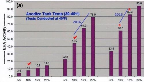
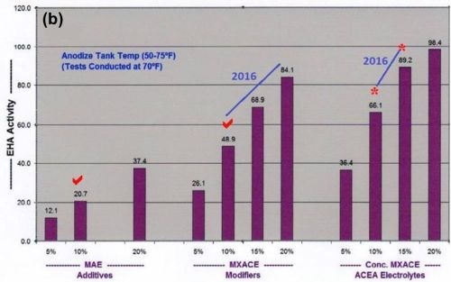
Figure 1 - Comparative analysis data showing the effects of multi-purpose anodize electrolyte additive levels, mixed amino-complex electrolyte modifiers (MXACE) and MXACE concentration in amino-carboxylic electrolytes on endothermic heat activity (EHA) at solution temperatures of (a) 40°F and (b) 70°F.
Sulfuric / organic anodize process tanks
The following MBO formulations for sulfuric / MBO electrolytes tested in production make it far more economical to reach the high EHA levels noted on the bar graphs for 2016.
Type III hard anodize tank formulation
HA - MBO - TXC 361
Sulfuric Acid (free) 12.0 - 15.0 vol%
ACXP 3.0 vol%
TXC 361 5.0 wt% per volume
(Oxalic Acid 3.0 wt% per volume)
(Tartaric Acid 1.5 wt% per volume)
(Citric Acid 0.5 wt% per volume)
Total as TXC 361 5.0 %
Temperature 30 - 35°F
Current Density 25 - 50 A/ft2
Maximum Coating Rate 5 mil/hr
Type II - 23 Sulfuric / Hard Anodize Tank Formulation
SHA - MBO - TGLC 1441
Sulfuric Acid (free) 10.0 - 12.0 vol%
ACXP 3.0 vol%
TGLC 1441 5.0 vol%
(Tartaric Acid 0.5 wt% per volume)
(Glycolic Acid 2.0 vol%)
(Lactic Acid 2.0 vol%)
(Citric Acid 0.5 wt% per volume)
Total as TGLC 1441 5.0%
Temperature 60 - 85°F
Current Density 25 - 60 A/ft2
Maximum Coating Rate 4 mil/hr
Pore structure development and protection
Proper pore structure development and surface protection are very important during the entire anodize process. ACXP and MBO electrolytes promote development and provide protection at the microscopic pore structural level, which leads to a higher quality anodic coating. Total quality improvement (TQI) is realized in several areas:
- Better adhesive bonding properties
- Excellent dye capability / absorption
- Improved seal capability
Because of recurring pitting and blistering problems associated with certain aerospace alloys, proper pore structure development and protection cannot be overemphasized. To better illustrate the importance of MBO electrolytes and the protective properties of the ACXP additive, consider this real problem solving solution from our case files:
Background: Firearm parts (7075 Alloy) were being hard anodized successfully at an anodize facility which had been using our ACXP and mixed organic electrolytes for 12 years. After 65 years of service, the facility closed down and the firearms were moved to another anodize plant. Severe blisters developed, which (in some cases) could be shaved off with a razor blade, leaving obvious pits. One anodizer at the facility was very familiar with ACXP and mixed organic electrolytes, which he had access to because of his previous employment. He suggested an addition of ACXP and MBO (2 - 3%) to the anodize tank. The blisters miraculously disappeared after the addition. They continued to process parts (for about 60 days) until the blisters returned. Then, the anodizer added the rest of the ACXP and MBO he had on hand and once again the blisters disappeared.
After seeing this, the anodizer and his new employer called me. We had a brief conference call before I planned a trip to his facility. We surveyed his facility and set up our ACXP and MBO electrolytes at 5% in his hard anodize tank for all difficult alloys. At my suggestion, they also installed an ACXP spray rinse immediately after the anodize tanks. In addition to solving the blistering problem, they now run 2000 series alloys without burning, which had been a recurring problem in the past.
This clearly demonstrates the protection of the active pore structure against pitting in the anodize tank and rinse tanks. The pits are what lead to blisters in the coating, especially in the hot dye and seal tanks. The amino carboxylic acids and dicarboxylic groups form ionic complexes with the contaminating metals Cu / Fe / Zn present in the alloys, and also retard acid attack from the strong sulfuric hydrogen ion in the electrolyte.
Power supplies: rectifiers
Switch mode rectifiers have finally been perfected for higher voltage and amperage requirements (75 V - 3000 A). They have also become more popular for anodizing due to their economical compact design. We have decided to use switch mode power supplies for our anodic test evaluation cells (ATEC) because they also work quite well in the laboratory. A 30 V - 10 A unit is very compact (3" H × 8" W × 8" D) and only weighs 5 lb., allowing for excellent portability.
The standard power supply used by most anodizers is full wave, three-phase with constant voltage (CV) and constant current (CC) controls, suitable for most aluminum alloys. However, for greater efficiency and difficult alloys, the following design features should be specified for SCR rectifiers:
- Rectifiers should be capable of starting at an initial setting of 0 - 1.0 V maximum. This is critical for proper pore structure development.
- A secondary transformer center tap should lead directly to the negative aluminum cathode (no full wave bridge).
- Rectifiers should be secondary SCR due to voltage control and 60 cps phase controlled pulse.
- Rectifiers should be protected against excess ripple, voltage / current spikes and deviation. This can be accomplished with a fixed resistance bank or the FCD unit used for APCD. FCD and APCD have been discussed in past papers.7-10 This is an integral part of the Complete Spectrum Approach - electronics.
Special half wave rectifiers are preferred for processing all 2000 / 7000 series and heavy thickness salvage hard anodize (SHA). Also, the following design features and additions should be made to the rectifier:
- The rectifier should be capable of control from 0 - 2 V without surges.
- The Zig-Zag design should be used for the transformer secondary.
- A resistance inductance load should be connected across the rectifier output (10 - 25% of the load). The FCD unit used for APCD has been designed to meet this capability, along with the following advantages:
a) Removes voltage spikes and deviations
b) Initiates anodize at 2 - 5 V
c) Initiates higher current density at lower voltage
Auto-ranging variable pulse power package
The APS Group continues to present new improved anodic pulse technology which has been tested and proven in actual production on the anodize line. After a recent discovery, results have shown our new ACXP and MBO electrolytes working together to be very important additions to pulse-step-ramp (PSR), quick step ramp (QSR), and auto-ranging voltage / current pulse in these important areas:
- Alloy protection is improved before starting the ramp cycle.
- Surface finish activation is accomplished before starting the ramp cycle.
- Anodize is initiated and actually increased at lower voltages (2 - 5 V), via ACXP, MBO electrolytes and APCD working together.
- Extra anodic protection provided during long extended ramp cycles.
- Continued anodic surface protection provided after completion of total anodize ramp and run cycle.
In addition, with ACXP and MBO electrolytes working together, the pore structure development and final anodize finish have shown marked improvements in the following areas:
- Superior adhesive bonding applications on IC and IIB coatings
- Excellent dye absorption on all coatings
- Improved sealing for excellent corrosion resistance
- Improved surface finish on all Type III coatings
Variable pulse types and stages
The following improvements began with the 1968 Patent, followed up in 1984-1987 with SUR/FIN supplier demonstrations, and continuing refinements since 2003 with SUR/FIN presentations and technical papers.
Variable Pulse Types:
- Voltage / current pulse-step-ramp (2003-2015)
- Auto-ranging voltage / current pulse (2011)
- Auto-ranging APCD current pulse - FCD (2012)
- Low voltage-quick step ramp / QSR (2014-2015)
Anodize initiated / protected - ACXP @ 0 - 2 - 5 V
QSR promotes pore structure development (2- 10 V)
Variable Pulse Stages:
- Activation pulse stage - Type A (protected using ACXP)
- Bonding and conditioning pulse stage - Type BC
- Current density pulse at CCDR Stage - Type CCD
CCDR - constant current density ranging
Process procedure requirements
This very important part of the “Complete Spectrum” package has been developed with continual improvements made on the anodize process line for over 50 years. These nine requirements / concepts represent problem solving technology and methodology good anodizers know as the secrets to total quality improvement (TQI). Please note the latest additions and revisions listed in italics:
- Activation - 5 - 10 voltage / current pulse period
- Pulse-step-ramp / slow PSR / QSR
- Auto-ranging voltage / current pulse (high/low pulse increased with mixed organic electrolyte)
- Dwell times increased (2 - 7 min / 3 - 10 mils)(for proper pore structure conditioning)
- Amperage decay or drop-off (ADO)
- Constant current density ranging (CCDR)
- Ampere-hours versus process time (correction factors)
- Real time graphic observation (monitoring - analysis - reproducibility)
- Anodic pulse capacitance discharge (APCD)(low voltage - high CD / spikes and deviations)
The quick step ramp (QSR) was added in 2014 for Type IC thin film anodizing and modified for die cast alloys in 2015.
Auto-ranging voltage / current pulse was formally introduced in 2012. It has been included in our procedure requirements for 2016 due to two improvements: (1) high current density production anodize is improved for Type II and II hard anodize at elevated temperatures (70 - 85°F) and (2) auto-ranging high and low pulse amplitude has been significantly increased with the mixed (blended) organic sulfuric electrolyte for Type II and III hard anodize.
Anodic pulse capacitance discharge (APCD) initiates and promotes anodize at lower voltages (2 - 5 V) with higher current densities. This has been proven on 3000 - 5000 A power supplies. Also, voltage / current spikes due to malfunctions within the electronic power package are removed using capacitance discharge.
A fixed capacitance discharge unit (FCD) was connected across an older rectifier (25 years) and all of the voltage current spikes were removed. Please note the before and after graphic runs shown in Fig. 2.
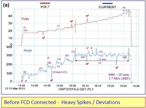
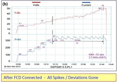
Figure 2 - Electrical characteristics (a) without and (b) with fixed capacitance discharge.
The following improvements were also noted with the fixed capacitance discharge:
- Anodize initiated (5-10 A/ft2) at 15.5 V as compared to 20 V
- Running time at CCDR extended by 33% before reaching 50 V
- Anodize coating thickness was 2.3 mils versus 1.7 mils without FCD
The fixed capacitance discharge (FCD) increases the amperage and current density at a lower voltage and throughout the entire anodize run.
Anodic test evaluation cells (ATEC)
Several different test cells have been developed for the electroplating industry. The three main cells, which have been used successfully for many years, are:
- Haring-Blum cell: for determining throwing power
- Hull cell: for current density and deposit appearance (as related to the bath chemistry)
- Assaf cell: for trouble shooting throwing power (in narrow recessed areas)
For anodizing however, very few cells have been developed. Over the years, we have developed several test cells for anodize, which have been designated as anodic test evaluation cells (ATEC) in past technical papers. A new ATEC is being modified and along with continuing research, will lead to another technical paper in 2017. We expect to be able to determine and / or control to a significant degree the following factors:
- Hard compact coatings without burning or powdering
- Pore structure during pulse-step-ramp
- Throwing power and distribution
- Anodize tank chemistry (ACXP and MBO electrolyte balance)
- Agitation and temperature
The BK switch mode power supply used for our ATEC cell has been retrofitted with APCD. This enables brush anodizing to be accomplished at high current densities (CD) and low voltages. Please note the high current density values at low voltages shown in the data logger graphs (Figs. 3 - 6) in the next section.
Data logger graphs
The ATS real time data logger graphs represent one of our most important contributions to the anodize industry. We have developed a new type of real time data logger system that can also be used as a semi-automatic controller with better results. A record of each process run can be kept on file. The data logger graphs presented here are as follows.
Process characteristics
Figure 3 shows a comparison between a standard sulfuric acid anodize (Fig. 3(a)) and anodic mixed / blended organic (MBO) chemistry with amino-complex protection (Fig. 3(b)). The standard process yielded a soft, powdery coating at 1.7 mils thickness after 42 min, while the MBO/ACXP process produced a compact hard coating at 1.5 mils thickness after 46 min.
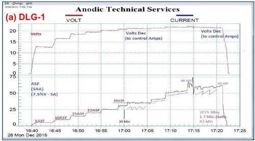
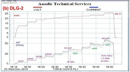
Figure 3 - Data logger graphs DLG-1 & 2: comparison of (a) a standard sulfuric acid anodize; step ramp with fixed capacitive discharge (FCD), 5 to 60 A/ft2 at 24 V and (b) anodic mixed / blended organic (MBO) chemistry (ATEC T-115) with amino-complex protection (ACXP); step ramp with FCD, 5 to 60 A/ft2 at 26 V.
Figure 4 shows a comparison between variations in the pulse-step-ramp mode, using a MBO/ACXP process. Fig. 4(a) utilizes a low pulse-step-ramp sequence, while Fig. 4(b) shows a modified low-to-high pulse-step-ramp sequence. In both cases, a hard compact coating is produced, 1.6 and 2.0 mils for (a) and (b), respectively.
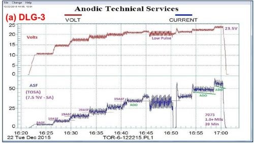
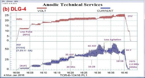
Figure 4 - Data logger graphs DLG-3 & 4: comparison of auto ranging pulse-step-ramp conditions: a mixed / blended organic (MBO) chemistry (ATEC T-115) with amino-complex protection (ACXP) sulfuric acid anodize; (a) low pulse-step-ramp with anodic pulse capacitance discharge (APCD), 5 to 60 A/ft2 at 23.5 V and (b) modified low-to-high pulse-step-ramp with APCD, 5 to 60 A/ft2 at 25 V.
It is interesting to note that a momentary loss of agitation at the 16:32-16:33 time point in Fig. 4(b) can be noted. Figure 5 shows an enlarged graph of the 16:28 to 16:36 time sequence, with the attendant current increase and voltage drop. Such a record of observation is invaluable in trouble-shooting.
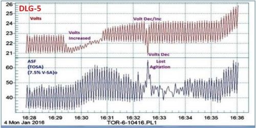
Figure 5 - Data logger graph DLG-5, showing the detailed plot of the 16:28 - 16:36 time sequence of Fig. 4(b) - DLG-4, where a momentary loss of agitation was observed.
Another comparison with standard sulfuric anodize performance is shown in Fig. 6, using another MBO electrolyte with amino-complex protection (ACXP). Auto-ranging pulse-step-ramp with anodic pulse capacitance discharge (APCD), from 9 to 24 V, was applied. In the standard sulfuric acid process, a 1.4-mil coating was produced at 75 A/ft2, while the MBO process yielded 1.9 mils, at 85 A/ft2, with 150 - 200% pulsing.
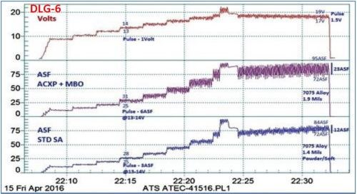
Figure 6 - Data logger graph DLG-6, a performance data comparison of a mixed / blended organic (MBO) chemistry (ATEC T-316) with a standard sulfuric anodize solution. Auto-ranging pulse-step-ramping with anodic pulse capacitance discharge (APCD), from 9 to 24V (lower plot; blue); the lower graph represents the current characteristics for the sulfuric acid process. The middle (violet) plot represents the current characteristics for mixed blend organic MBO chemistry, while the upper (red) plot shows the DC voltage across both tanks.
A study of pore development is shown in Fig. 7, based on the use of the data logger. Here, the characteristics of the standard tartaric sulfuric acid process are compared to a tartaric sulfuric acid-based MBO electrolyte. The effects of fast ramping and endothermic heating were of particular interest. As shown at the start of the plot sequence, a rapid 30-sec ramp to 10 V was too fast for pore structure development. With a more normal ramping rate to 10 V (starting at the 23:51 time point), it is seen that no current flowed and no pore structure development took place until a potential of 8 to 10 V was reached, for both processes. In the next phase (Starting just after 0.01 on the timeline), the current was first ramped to 50 A/ft2 (off the top of the scale), before turning the voltage back to 24 V to prevent burning. At this voltage, the operating current density was 20 A/ft2 for the standard tartaric sulfuric acid process and 35 A/ft2 for the tartaric sulfuric MBO solution. With the latter, the end result was a 1.0-mil thick coating with an excellent microfinish, produced through endothermic heat absorption during the coating formation process. On the other hand, the standard tartaric sulfuric process exhibited a rise in current, indicating no endothermic heat absorption. The result here was a soft coating with a comparatively low thickness of 0.6 mil. Effects of various ramp rates on the pore development, and the observation of endothermic heat absorption to produce an improved finish with the tartaric sulfuric MBO process are evident.
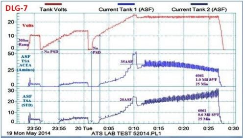
Figure 7 - Data logger graph DLG-7, a performance data comparison of a tartaric acid-based (MBO) chemistry with a standard tartaric sulfuric anodize solution.
Production applications and training
Data logger graphs are invaluable in training in the field of anodizing. Figure 8 shows the current voltage characteristics of a run of aircraft jet engine parts (2000 series Al). Here the effects of various elements of anodize technology, including manual ramping, pulse-step-ramping, auto-range pulsing and anodic pulse capacitance discharge are readily illustrated.
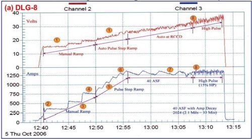
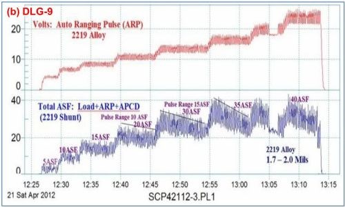
Figure 8 - Data logger graphs DLG-8 and 9, part of an anodize training program, showing a run of aircraft jet engine parts (2000 series), showing (a) several characteristics over time, including manual ramping (12:40 to 12:50 timeline), pulse-step-ramping (12:50 to 12:56), a 40 A/ft2 run with current decay (12:56 to 13:08) and high pulse effects (13:08 to 13:13) and (b) the voltage-current characteristics of auto-range pulsing (ARP) and anodic pulse capacitance discharge (APCD).
Work with 7075 helicopter production runs is shown in Fig. 9, showing a permanent data logger record for this particular production run including dwell times for masking, racking and the like. The electrolyte used mixed / blended organic (MBO) chemistry with anodic complex protection (ACXP). In Fig. 9(a), the full run is shown, while Fig. 9(b) shows the initial cycle, complete with the desired constant current density ranging (CCDR) and amperage drop-off.
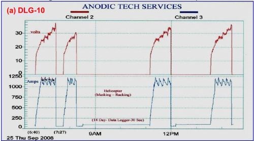

Figure 9 - Data logger graphs DLG-10 and 11, representing a permanent record for a production run of 7075 helicopter production parts using an MBO electrolyte and ACXP chemistry: (a) the complete cycle, including dwell times for part masking and racking, etc. and (b) the initial cycle in DLG-10 showing constant current density ranging (CCDR) and amperage drop-off (ADO).
Brush anodize, the anodizing analog to brush plating, is a reality, and its characteristics are shown in the data logger plots of Fig. 10. Figure 10(a) shows the current-voltage characteristics of a selective brush power supply operating at 80 A/ft2 and 3 - 6V. Fig. 10(b) shows the comparison with a standard power supply also operating at 80 A/ft2. Again, the graphic log is useful in recording specified constant current and amperage decay features. The brush anodize, given application on a specific area, produces a coating with less power. The higher power realized with a standard power supply can generate excessive heat, adversely affecting the pore structure.
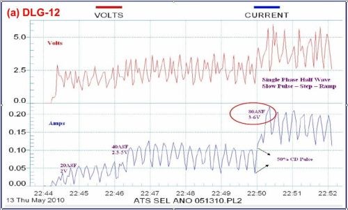
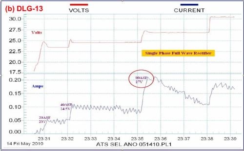
Figure 10 - Data logger graphs DLG-12 and 13, comparison of (a) characteristics of a selectiove brush anodize power supply with (b) those of a standard power supply (~ 80 A/ft2).
Conclusions
- Mixed / blended organic (MBO) electrolytes are formulated with high concentrations of carboxylic, polycarboxylic and hydroxy polycarboxylic acids which are beneficial for all sulfuric acid anodize processes.
- MBO electrolytes should become a part of all sulfuric anodize processes due to more demanding quality, specifications and production requirements.
- Preferred MBO electrolytes have multiple carboxy and hydroxy groups which are beneficial for all sulfuric anodize processes.
- MBO electrolytes should be mixed / blended with at least three choice carboxylic acids, which have been tested and proven for 12 years at two production anodize facilities.
- MBO acids act as secondary electrolytes in Type II and III anodizing, buffering the strong sulfuric hydrogen ion, which reduces the tendency to burn or powder.
- MBO electrolytes provide anodic surface activation during the ramp period.
- MBO electrolytes and ACXP (2015 / 16 papers), when used together, accelerate maximum anodic surface activation and protection before and during the pulse-step-ramp period.
- Sulfuric acid attack and field effect dissolution are reduced most effectively when MBO electrolytes and ACXP are working together.
- MBO electrolytes and ACXP provide maximum protection during tank loading and throughout the entire anodize cycle to the rinse tanks.
- MBO electrolytes promote heat absorption and pore structure development which leads to compact hard anodize coatings.
- MBO electrolytes and ACXP chemistry used together multiply and enhance EHA heat absorption in all sulfuric Type II, 23 and III anodize processes.
- MBO electrolytes promote amperage decay (ADO) which leads to faster anodize build up.
- Type II, 23 and III hard anodize can be accomplished over a wide current density range (20 - 80 A/ft2) using MBO electrolytes and ACXP chemistry working together.
- Type II, 23, III and salvage hard anodize can be accomplished over an expanded temperature range (25 - 85°F) using MBO electrolytes and ACXP working together.
- High and low pulse current amplitude is increased 150 - 200% at the same auto-ranging voltage pulse setting.
- When using MBO electrolytes and ACXP together, pore structure development and the final anodize finish have shown marked improvements in the following areas:
- Superior adhesive bonding applications
- Excellent dye absorption
- Improved sealing and corrosion resistance
- Improved surface finish on all Type III coatings
General references
- D.C. Working, U.S. Patent 3,343,943 (1969)
- F.C. Schaedel, U.S. Patent 3,418,222 (1968)
- F.C. Schaedel, U.S. Patent 4,152,221 (1979)
- P. Kljucaricek, et al., U.S. Patent 4,879,018 (1989)
- F.C. Schaedel, “Anodize Additives and Pulse Ramp Systems Optimizing the Chemistry and the Power,” Proc. AESF SUR/FIN 2003, Milwaukee, Wisconsin, pp. 71-84 (2003).
- F.C. Schaedel, “The Complete Spectrum Guide to Top Quality Anodizing: Maximizing Efficiency and Energy Savings ,” Proc. SFIC SUR/FIN 2006, Milwaukee, Wisconsin, pp. 168-187 (2006); also Plating & Surface Finishing, 93 (12), 38-44 (2006).
- F.C. Schaedel, “Realizing New Limits Using Anodize Discharged Surface Activation and Conditioning for Type II (23) and Type III Anodize on All Alloys, Proc. NASF SUR/FIN 2008, Indianapolis, Indiana, pp. 429-440 (2008).
- F.C. Schaedel, “The Leading Edge Guide to Top Quality Anodizing Using the Complete Spectrum Approach with One Universal Type I - II - III - (123) Mixed Electrolyte,” Proc. NASF SUR/FIN 2011, Rosemont, Illinois, Presentation: Session 10, June 14, 2011; Summary: Products Finishing - NASF Report, 76 (9), 14 (2012); Full Paper: Products Finishing, http://short.pfonline.com/NASF12Jun1, (2012).
- F.C. Schaedel, “New and Unique Variable Pulse Ramp Technology for Maximizing Pore Structure Conditioning in Type IC, II, III and 123 Anodize With Greater Efficiency and Energy Savings,” Proc. NASF SUR/FIN 2012, Las Vegas, Nevada, Presentation: Session 2, June 12, 2012.
- F.C. Schaedel, “Aerospace Anodizing in a Non-Chrome World ,” Proc. AAC Conference, 2013.
- J. Runge, “Interfacial Phenomena in 7000 Series Alloys and Their Impact on the Anodic Oxide,” Proc. AAC Conference 2013.
- F.C. Schaedel, “Unique New Thin Film Anodize Technology for Superior Adhesion Promotion, Bonding and Microfinish using One Universal Electrolyte with Type IC, IIB and III Capabilities,” Proc. NASF SUR/FIN 2014, Cleveland, Ohio, Presentation: Session 1, June 9, 2014.
- F.C. Schaedel, “Optimizing Non-Chrome Anodize Processing Solutions with New Amino Complex Ion Protective Chemistry Using the Complete Spectrum Approach,” Proc. NASF SUR/FIN 2015, Rosemont, Illinois, Presentation: Session 3, June 9, 2015.
About the author

Footnote
*Corresponding author:
Fred C. Schaedel
Anodic Technical Services
Alpha Process Systems
14600 Goldenwest St., Suite A206
Westminster, CA 92683
Phone: (714) 894-0109
Cell: (714) 728-5639
Fax: (714) 894-0179
Email: fcsaps@yahoo.com; info@alphaprocess.com
Related Content
Highlights from SUR/FIN 2023
Products Finishing offers a recap of some of the topics that were top of mind at the SUR/FIN 2023 finishing industry trade show.
Read MoreConnect, Collaborate and Contribute to the Industry at SUR/FIN 2024
Atlanta, Georgia, is the home to this year’s NASF SUR/FIN conference and trade show.
Read MoreNASF/AESF Foundation Research Project #121: Development of a Sustainability Metrics System and a Technical Solution Method for Sustainable Metal Finishing - 15th Quarterly Report
This NASF-AESF Foundation research project report covers the twelfth quarter of project work (October-December 2023) at Wayne State University in Detroit. In this period, our main effort focused on the development of a set of Digital Twins (DTs) using the Physics-Informed Neural Network (PINN) technology with application on parts rinsing simulation.
Read MorePractical Observations in Surface Chemistry and Boundary Layer Control to Enable Scalable Electrochemical Operation - The 57th William Blum Lecture
This paper is based on the 57th William Blum Memorial Lecture at SUR/FIN 2023, in Cleveland, Ohio on June 8, 2023, by Dr. Tim Hall, recipient of the 2023 NASF Scientific Achievement Award. It focuses on the practical effects of controlling the boundary and surface chemistry on a wide range of electrochemical applications. After a brief introduction to the concept and principles of surface and boundary layer properties during electrochemical processes, the use of this approach in controlling various physical properties during electroplating and electrochemical finishing is discussed, including controlling coating stress and metal composition, as well as enabling simple water-based electrolytes to polish passive or complex materials.
Read MoreRead Next
Delivering Increased Benefits to Greenhouse Films
Baystar's Borstar technology is helping customers deliver better, more reliable production methods to greenhouse agriculture.
Read MoreEducation Bringing Cleaning to Machining
Debuting new speakers and cleaning technology content during this half-day workshop co-located with IMTS 2024.
Read MoreA ‘Clean’ Agenda Offers Unique Presentations in Chicago
The 2024 Parts Cleaning Conference, co-located with the International Manufacturing Technology Show, includes presentations by several speakers who are new to the conference and topics that have not been covered in past editions of this event.
Read More





.jpg;maxWidth=300;quality=90)


