The Tribology of Contact Finishes for Electronic Connectors Part I: Mechanisms of Friction and Wear
This paper is an expanded treatment of the first part of the William Blum Lecture presented at SUR/FIN 1988 in Los Angeles by Dr. Morton Antler, 1987 AESF Scientific Achievement Award recipient. The subjects covered include friction, mechanical wear, fretting corrosion and frictional polymerization—all vital processes that affect the performance of contact finishes in electronic connectors.
By Dr. Morton Antler
Recipient of the 1987 William Blum AES Scientific Achievement Award
(Originally published as Plating & Surface Finishing, 75 (10), 46-53 (1988).)
ABSTRACT
This paper is an expanded treatment of the first part of the William Blum Lecture presented at SUR/FIN 1988 in Los Angeles by Dr. Morton Antler, 1987 AESF Scientific Achievement Award recipient. The subjects covered include friction, mechanical wear, fretting corrosion and frictional polymerization—all vital processes that affect the performance of contact finishes in electronic connectors. The dominant wear mechanisms (i.e., adhesion, abrasion and fretting) are also discussed. Substrate and lubrication effects on the tribology of contact finishes will be elaborated on in a second paper covering the final half of Dr. Antler’s Blum Lecture to be published in the NASF Report for March 2014. A printable PDF version of this first part is available by clicking HERE.
Introduction
An electric contact is the heart of separable connectors and printed circuit boards, instrument slip rings, switches and other current-carrying devices. These components are designed to allow the engagement or disconnection of an electronic assembly or to permit one contact surface to be moved while it touches another. Because the contact resistance between mating surfaces must be low, gold and other noble metals are used extensively. Tin and tin-lead solder are exceptions because their deformability allows insulating surface oxide films to be readily broken when contact is established.
The main applications of contact-containing components have been for telecommunication equipment, computers, aircraft and aerospace devices, various instruments and military hardware. However, the use of consumer products that contain large numbers of separable contacts is growing rapidly, especially in the automotive and entertainment fields. In developing finishing technologies for the noble metals, the high cost, limited availability and general unsuitability of these metals as structural contact materials have been the major challenges.
In this paper, metal finishing is interpreted broadly to embrace the diverse processes of electroplating, electroless plating, cladding and a variety of physical coating and surface-modification methods such as ion plating and ion implantation. Finishing can be extended to post-plating passivation treatments for porous deposits and even to contact lubrication when the application of a lubricant is made on the plating line directly following metal deposition.
Tribology* is important because contact coatings are generally thin, and it is necessary to maintain the integrity of the deposit during sliding to minimize exposure of base underplatings and substrates. The requirement for low friction is becoming more critical as the numbers of contacts in separable connectors increases. While resistance to corrosion and tarnishing and the thermal stability of contact resistance have always been of concern in the selection of finishes, it is not often realized that the tribological requirements of coatings have been of equal or greater importance in molding metal finishing practices. As will be discussed for electrodeposits, the incorporation of cobalt or nickel in gold electrodeposits, the practice of using a gold flash on palladium, and the use of nickel underplates developed largely because it was realized that these practices would improve the tribological performance of the contact finish.
The objective of this review is to present the tribological background behind modern practices in the metal finishing of contacts and provide guidelines for selecting finishes for electronic connectors. Some thoughts on the needs and possible future developments are also given.
Contact wear mechanisms
Mechanical wear involves loss of material as loose particles from solid surfaces. In special cases, the following are also classified as wear: dimensional changes or roughening due to metal transfer in the absence of loose-particle formation, the cracking of brittle coatings, and mechanically induced flow without measurable transfer or loss (i.e., burnishing).
Adhesive wear occurs when surfaces undergo metal transfer. Adhesive bonds are formed between touching asperities that are stronger than the cohesive strength of the metal. This bond formation results in plucking of material, which then may be lost from the surface to which it transfers during subsequent traversals.
Many metal systems operate at widely different rates of adhesive wear, from mild to severe, and the scale of wear can change in a narrow range of load (Fig. 1). Below the transition load, wear debris is finely divided; above it, debris is coarse. Provided the surfaces are very clean, sliding with noble metals is in the severe regime even under small loads (e.g., 1 g for pure gold plate and 10 g for cobalt-gold alloy deposits). In practice, the transition loads are related to the removal during sliding of adventitious contaminants such as adsorbed organic air pollutants. Such materials can be strikingly protective,1 but, when repeat-pass sliding occurs too quickly for the contaminants to be renewed, the transition to severe wear will occur.
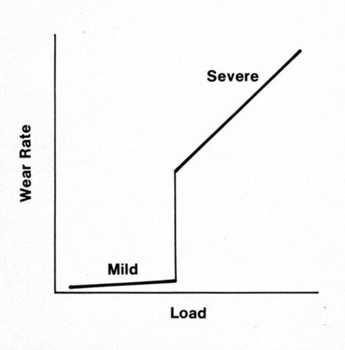
Figure 1 - Regimes of wear.
The severe adhesive wear of contact metals is a process called prow formation,2 which can be described phenomenologically as follows for contacts of the same material. When the contacts are of different sizes, metal transfers from the part with the larger surface involved in sliding to that with the smaller surface (e.g., from flat to rider in a rider-flat apparatus). A lump of work-hardened metal (the prow) builds up and in turn wears the flat by continuous plastic shearing or cutting, while the rider does not wear (Fig. 2). Prows are lost from the rider by back transfer to the flat or as loose debris. Prows consist of thin, overlapping layers of metal (Fig. 2f, back transfer prow). If the rider always traverses virgin metal, prow formation continues indefinitely.
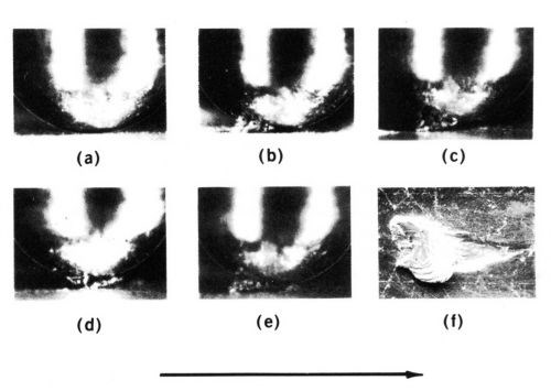
Figure 2 - Prow formation mechanism of sliding for a rider 3.2 mm in diameter on flat specimens with gold contacts and a 500-g load. Shown are (a) start of run, (b) well-developed prow, (c and d) loss of portion of prow by back-transfer to flat, (e) newly formed prow and (f) prow back-transferred to flat consisting of overlapping thin layers of metal. The arrow indicates the direction of movement of the flat.
When contact members of the same material are identical in size and shape, an initial prow can come from either member. However, once transfer occurs, the receptor becomes the rider, and the opposing surface wears. With dissimilar metals, prows will form even when the flat is harder than the rider provided this difference is not greater by a factor of about 3. The friction and contact resistance of the system are determined by the prow metal. Thus, a palladium-plated rider sliding on a gold-plated flat behaves as does gold on gold, while a gold rider on palladium slides like palladium on itself.3
Another example is that of electrodeposited cobalt-gold mated to pure gold or to gold-silver alloys such as 70/30 Au-Ag. These wrought metals are much more prone to severe adhesive wear than the electrodeposit.4 If the larger surface involved in sliding is made of the more adhesive, wear-resistant metal, then the sliding performance of the couple will be superior to the sliding performance when the contact materials are reversed. For this reason, contacts of edge connectors for printed wiring boards made of wrought gold-silver alloys are generally acceptable when the board fingers are plated with cobalt-gold.
Whenever dissimilar metals are mated and metal transfer occurs, the interfacial layer determines the behavior (including wear rate, coefficient of friction, contact resistance, and chemical properties); the equilibrium composition may take considerable repetitive sliding to develop; and the relative sizes of the contact regions of the members in the couple are as important as the metals themselves in determining the interfacial properties. This important concept extends beyond prow formation.
Prow formation occurs with gold, palladium, platinum, silver, copper, copper-beryllium alloys, phosphor bronzes, lead, aluminum, iron and many other metals. Metals that do not work harden, such as indium at room temperature, fail to form prows.
If the rider traverses the same track repetitively, prow formation eventually ceases and is replaced by rider wear, a mechanism in which the smaller contact surface wears. Rider wear occurs primarily by transfer to the flat with some loose-particle formation. In rider wear, the flat gains mass (Fig. 3). The transition is due to the accumulation of sufficient back-transfer prows on the flat to increase its hardness in all places to the level of extreme work hardening. When the surface of the flat reaches the hardness of prows, routing of the flat ceases and the rider begins to wear.
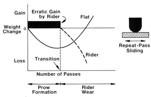
Figure 3 - Schematic diagram showing weight changes of rider and flat in repeat-pass sliding, from prow formation through the transition and into rider wear.
It has also been found that there is a roughness of the flat above which prow formation does not occur. This roughness is dependent on the load, hardness and ductility of the metal, and is related to the size of the prows. For pure gold, the critical roughness is 0.6 to 1.3 pm center line average (c.l.a.) at 100 g.5 The harder and less ductile the metal, the smaller is the critical roughness. This fact may explain why prow formation is unlikely to occur with rhodium, ruthenium and other hard, brittle electrodeposits. Because prow formation dominates the sliding of many contact metals in the severe regime, studies6 have been performed to determine the effects of load, numbers of traversals and track length on this process.
Adhesive wear of gold
Gold electrodeposits are the most widely used contact materials. Adhesive processes dominate their wear. The properties that control wear behavior were studied by the author.7 Table 1 lists typical mechanical-property data for gold plated with direct current. The ranking of different types of gold in order of increasing durability is based on several reports.5,8-10 Cobalt-hardened gold exhibits the best wear resistance. Gold-silver and gold-cadmium alloys are next in durability.
Table 1 - Properties of gold electrodeposits from direct current processes.

aDetermined by combustion microanalysis.
bObtained from metallographic sections on thick deposits at 25 g.
cVaries according to deposit thickness and method of measurement; values given are representative.
dDescribed in Reference 9.
eAdditive-free hard gold described in Reference 10.
fMay contain small amounts of organic or metalloid brighteners.
gNickel-hardened golds have properties comparable to those of this cobalt-hardened gold deposit. Deposits with similar characteristics are available from many commercial processes.
The reasons for differences in wear behavior have been the subject of conjecture. When hard golds, first the silver alkaline cyanide and then the cobalt- and nickel-hardened types, became available, it seemed that the superiority of their adhesive wear properties relative to the adhesive wear of soft, pure gold could be related to hardness. It later became apparent that this explanation was incomplete because tests with wrought gold alloys of comparable hardness showed the wrought gold to be inferior.11 The discovery that a hard, relatively pure gold (Table 1, 24-Karat Hard Gold) wears poorly further underlined the inadequacy of the simple hardness theory.
A later suggestion11 was that co-deposited polymeric organic materials12 in the cobalt- and nickel-hardened golds were acting as lubricants. Table 1 lists typical carbon analyses of some golds as an indication of their polymer content. This explanation also proved inadequate once it was realized that some hard deposits that contain significant codeposited polymers were much more prone to severe adhesive wear than the cobalt- and nickel-hardened gold electrodeposits. The silver alkaline cyanide and, especially, the additive-free hard gold (AFHG) are examples of this fact. It has also been found that even cobalt-hardened golds containing considerable polymers could wear by prow formation at low load provided their surfaces were scrupulously clean.
Two problems long stood in the way of a rational understanding of the wear of gold electrodeposits: (a) lack of information on the structure of Co-deposited polymers and (b) little physical-property information about the gold electrodeposits, other than the bulk hardness from sectioned deposits. Limited data are now available, and typical deposit ductilities are given in Table 1.
The structure of a cobalt-hardened gold deposit has been elucidated. The polymers consist in part of a complex cobalt cyanide compound,12 which is uniformly distributed in the deposit as particles ranging in diameter from 2 to 7 nm.13 Some polymer particles may be larger.14 From physical metallurgy theories that describe the effects of finely divided particles on the mechanical properties of solids, both the hardness and the low ductility can be attributed to these codeposited materials.
It seems that the most durable deposits are those with fairly low ductility (i.e., with elongations of about 0.4%). In addition to the cobalt-hardened, acid bright gold deposit in Table 1, polymer-containing 0.28% nickel-hardened gold and 1.3% cobalt plus 0.55% indium-hardened gold have similar durabilities and mechanical properties.5
A hypothesis for the ranking of gold deposits according to their adhesive wear resistance is based on the phenomenon of junction growth, which is controlled by the ductility and hardness of a solid. Junction growth14 occurs when adherent asperities undergo tangential stress. There is an increase in the area of asperity contact before the junction shears, particularly with ductile materials (Fig. 4). Junction growth causes high friction.
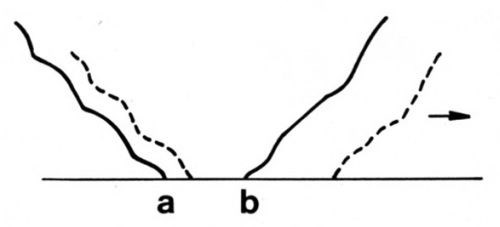
Figure 4 - Schematic representation of junction growth. Normal load deforms asperity so that contact occurs along line ab. When a tangential stress is imposed in the direction of the arrow, the junction grows, as shown by the dashed lines, and the two surfaces move together slightly.
The formation of prows with attendant transfer and the occasional loss of prows to form loose debris is closely related to junction growth, and a prow in its initiation and growth stages can be considered to be a single large junction.16 In summary, this view, coupled with friction theory, suggests that an interplay of three factors controls adhesive wear. For best performance, the contact finish should (a) be hard so as to limit the area of initial contact, (b) have low ductility to limit junction growth and (c) be lubricated to inhibit asperity adhesion.
Thus, high hardness alone, with or without codeposited polymers, is insufficient to provide good wear resistance (Table 1, 24-Karat Hard Gold and AFHG), while hardness coupled with relatively low ductility provides good performance. However, it is possible for a gold deposit to be so brittle that it would fracture under normal load.17 The efficacy of contact lubricants in compensating for the poor wear of ductile gold deposits, both hard and soft, is also well known.9,10,18
It is possible to alter the composition, structure, and properties of gold electrodeposits by varying the current waveform during plating. For example, cobalt-hardened gold19 plated in a cyanide solution was substantially free of polymers compared with gold plated in the same solution using direct current. Both pulse- and de-plated deposits have been prepared with similar cobalt levels and hardness. However, bend tests showed that the de-plated, cobalt-hardened gold deposit was much less ductile, and sliding tests showed the de-plated gold deposit was also significantly less prone to adhesive transfer and wear. This finding is in accord with the previous analysis, which shows that high ductility degrades adhesive wear resistance.
Recent developments
Gold plating processes often have relatively narrow "windows" from which electrodeposits with satisfactory tribological properties can be obtained, and this is especially true for high speed systems. In a recent study20 with typical cobalt-gold and nickel-gold deposits, the solution compositions and bath operating conditions were varied, and the sliding characteristics of the deposits were evaluated using connector contacts in a tribotester having a rider-flat configuration. Both members were plated with 5 µrn of gold, and sliding was at 150 g for 500 cycles. Figure 5 illustrates some of the results. The coefficient of friction is plotted against deposit potassium, solution cobalt, and plating current density. The line on the surface within which the crosses lie delineates the "good" wear region. Good wear resistance was synonymous with coefficients of friction of 0.26 or less and "bad" wear with larger values.

Figure 5 - Effect of cobalt concentration of electrolyte and cathode current density on potassium content of the deposit. The plus sign (+) represents experimental conditions resulting in "good" or "very good" wear. The numbers on the surface are the coefficients of friction.20
The physical properties of these deposits were not determined, but they obviously depended on the process. Curves such as these can be used for plating process control because they define the operating window for deposition. This window yields gold deposits having satisfactory tribological characteristics. In a more general sense, it can be argued that the performance of a deposit is dependent on the process. This premise is true not only of gold but also of palladium, palladium-nickel, rhodium, tin-lead solder and any other engineering finish.
Abrasive wear
Two-body abrasive wear is caused by the plowing of a surface by an opposing contact material that is rough and substantially harder. When the abrader initially is a loose particle that can be embedded in one surface, wear is termed three-body abrasion. Displaced material can be removed in chip form, as in cutting, or can flow to the sides of the groove with little or no loose-particle formation.
Brittle fracture occurs with materials having low tensile strengths compared with their compressive strengths. The surface develops cracks across the wear track during sliding (Fig. 6). Many contact materials, including rhodium and cobalt-gold electrodeposits, are relatively brittle and likely to fracture when abraded.
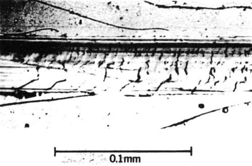
Figure 6 - Wear track on a 65/35 Sn-Ni electrodeposit 12 µm thick with a 0.43-µm-thick overplate of cobalt-gold alloy (diamond rider, 90° conical tip with a radius of 0.1 mm, single pass at a load of 200 g). Deposit shows brittle fracture.
As a class, wrought noble contact metals, such as cladding, are more ductile than their electroplated counterparts. Therefore, their abrasion resistance is superior. The two-body wear indices of a clad pure gold deposit and a cobalt-gold deposit with similar thicknesses were determined by drawing a diamond stylus across the deposits (Fig. 7). Electrography21 was used to measure wear. Electrographs are obtained by pressing moist, chemically treated paper against the worn specimen under the influence of a DC voltage. An imprint of the track appears in the paper, and colored spots reveal substrate regions that have been exposed. The ratio of the length of colored track to the total track length multiplied by 100 is defined as the wear index. Although the gold electrodeposit in Fig. 7 was supported by a hard underplate and substrate, the clad metal was clearly superior. By the same token, the adhesive wear resistance of clad pure gold is inferior to that of cobalt-gold electrodeposits.
For the majority of cases in which noble metal contacts are used, adhesive wear is more important than abrasive and brittle fracture wear. The selection of an electrical contact material generally should be made by first considering its adhesive wear properties. If it is practical to employ lubricants that can alleviate adhesive wear, then metals with superior abrasive wear characteristics can sometimes be used.
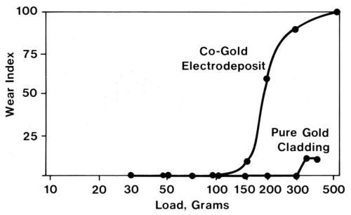
Figure 7 - Electrographic wear indexes from two-body, abrasive-wear runs with two 2-µm-thick gold coatings, namely, a cobalt-gold electrodeposit on a 2.5-µm-thick nickel underplate on a copper-beryllium substrate and a pure gold clad inlay with a nickel interliner on a copper-nickel-tin alloy substrate (single-pass runs at various loads with a conical diamond rider).
Fretting and fretting corrosion
Fretting wear occurs as a result of oscillatory movement of small amplitude, generally 130 µm or less.22 Because motion is limited, debris accumulates between the contacts rather than emerging free. The wear debris from base metals contains products of reaction with the environment (e.g., oxides), and, in this case, the wear process is termed fretting corrosion. Small movements may occur when a component is subjected to vibration, mechanical shock or thermal excursions. Oxide debris can cause substantial increases in the contact resistance of electronic connectors having base metal contacts.
Laboratory fretting studies of contact materials are relatively new. It is difficult to determine the behavior of materials under fretting conditions with connectors or other components fixed to vibration tables because the mass, physical dimensions of the components and any equipment to which they are mounted, and the method of attaching electrical leads can either attenuate or exaggerate the forces exerted on the contacts. When the primary interest of the investigator is in the behavior of materials, it is desirable to exclude component effects by using an apparatus that forces movements under precisely controlled conditions. This point seems to have been overlooked in some of the research that led to contradictory claims about the fretting of contact finishes.23,24 Only when the behavior of an actual device is of interest is it appropriate to examine the device itself.
The author has used an apparatus (Fig. 8) in which a stationary rider (usually a ball, a contact rivet, or a copper rod with a hemispherical end - any of which can be plated by conventional methods) is dead weight loaded against a plated flat specimen mounted on a ball slide. A computer-controlled stepping motor displaces the slide over a small amplitude at a controlled frequency. Contact resistance is measured through leads with an appropriate electrical circuit and is recorded by the computer. This apparatus and experimental procedure have been described previously.25
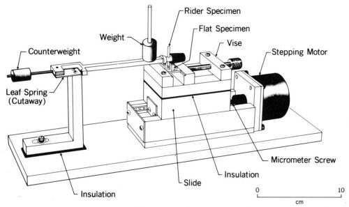
Figure 8 - Fretting test apparatus.
Typical data illustrating the contact-resistance instability of contacts plated with tin-lead solder are given in Fig. 9.26 From an initial value of 0.001 Ω, contact resistance increases to 10 Ω in only a few thousand cycles of fretting at an amplitude of 10 µm. Furthermore, solder plate mated to gold degrades even more rapidly (Fig. 9). An explanation for the latter behavior based on the mechanics of oxide-film fracture has been given.26 An oxide that transfers from the thin layer of solder to the much harder gold early during fretting was shown to be less readily fractured, thus having lower contact resistance, than oxides on base-metal contacts having identical hardness. The opposing contacts have identical hardness when the contacts are composed of the same material. Figure 10 is a worn contact surface from fretting tin-lead against itself. The wear spot is covered with a thick, insulating fudge of mixed tin and lead oxides, and debris is piled up around the periphery of the wear scar.
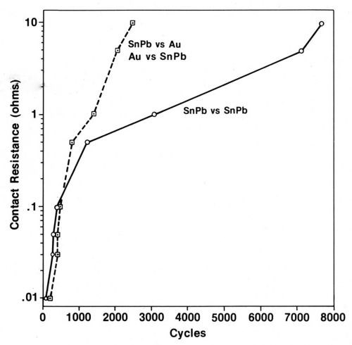
Figure 9 - Contact resistance vs. numbers of fretting cycles for tin-lead solder against itself compared to gold vs. tin-lead-plated contacts. The contacts were not lubricated (Wipe distance, 10 µm; normal load, 50 g).
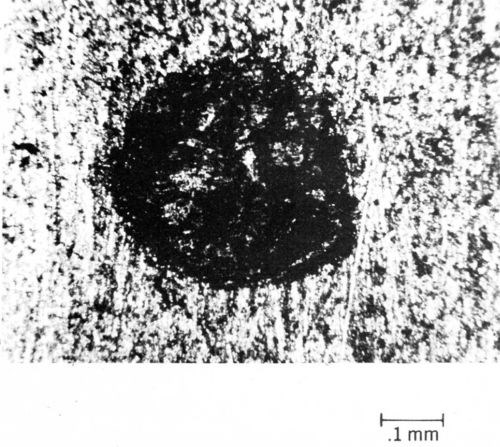
Figure 10 - Worn spot on tin-lead-plated contact after fretting.
It has also been found that fretting may be a cause of contact-resistance change in connectors with noble-metal contacts due to wearing out of the surface finish and resultant exposure of underlying base metal.27 A comprehensive review of the electrical effects of fretting connector contact materials has been published previously.28
Frictional polymerization
Frictional polymerization can occur during sliding and fretting with palladium, rhodium and other platinum-group contact metals and alloys29 due to their catalytic activity. Adsorbed organic air pollutants are converted into complex, solid, insulating contaminants of high molecular weight. Movement enhances this effect, but its role may simply be to dislodge the reaction product, thus producing a continuous conversion to polymers in the area of slide.
Accumulation of frictional polymers, while resulting in the inhibition of wear, unfortunately causes the contact resistance to increase. An example of contact-resistance changes caused by frictional polymers in a fretting test is given in Fig. 11. Lightly loaded sliding contacts, such as instrument slip rings that operate in the 2- to 10-g load range, are particularly prone to be degraded by frictional polymers. Even more heavily loaded (50 to 200 g), separable connector contacts can be unreliable due to fretting when coated with catalytically active metals.
Gold-plated contacts have low and nearly invariant contact resistance until the gold is worn away when sliding under the same conditions as described in the preceding paragraph. A gold flash on palladium-plated contacts is only marginally useful in protecting them from contact-resistance degradation due to fretting in the system of gold-flashed palladium plate mated to itself,30 although a flash of cobalt-gold is slightly better than pure gold.28 Fretting tests were conducted in room air using 80/20 Pd-Ni alloy mated to itself, a 20-µrn wipe, a 50-g load, and a frequency of 4 Hz (Fig. 11). It was determined that a gold flash on the electrodeposited alloy also is of only small benefit in extending the numbers of cycles of fretting before contact resistance increases. However, when any of these finishes is mated to a thick gold plate, solid pure gold or some solid gold alloys, contact resistance will remain stable for lengthy runs due to transfer from the gold contact to the palladium-plated part early in the run. This transfer converts the system to one that is all gold.28 An exception occurs when the gold alloy is harder than the palladium; this situation causes transfer in the opposite direction and thereby creates31 an all-palladium interface.
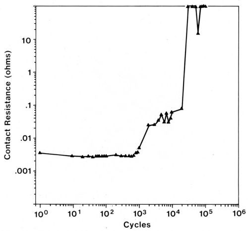
Figure 11 - Contact resistance vs. number of fretting cycles for a palladium rider (3.2 mm in diameter) tested against a palladium flat using a 20-µm wipe, a 50-g load, and a frequency of 4 Hz. The increase in contact resistance is due to the formation of frictional polymers.
Summary
Friction, mechanical wear, fretting corrosion and frictional polymerization play vitally important roles in the performance of contact finishes in electronic connectors. Their tribological behavior largely determines contact plating practices. Adhesion, abrasion and fretting are dominant wear mechanisms. Adhesive wear involves metal transfer between sliding and stationary surfaces. Hardness and ductility are controlling factors. Abrasive wear occurs when there is a large difference in the hardness of the contact materials and one of the contact materials is relatively rough. Fretting results in the accumulation of wear debris in the contact zone. Fretting corrosion develops with base metals. Frictional polymers may form when platinum-group metals are involved. Fretting corrosion and frictional polymerization can cause high contact resistance.
References
1. M. Antler, IEEE Trans, on Parts, Hybrids, and Packaging, PHP-10, 11-17 (1974).
2. M. Antler, Wear, 7 (2), 181-204 (1964).
3. M. Antler, ASLE Trans., 5 (2), 297-307 (1962).
4. M. Antler & E.T. Ratliff, IEEE Trans. on Components, Hybrids, and Mfg. Tech., CHMT-6 (1), 3-7 (1983).
5. M. Antler, ASLE Trans., 11 (3), 248-260 (1968).
6. M. Antler, ibid., 13 (2), 79-86 (1970).
7. M. Antler, IEEE Trans. on Components, Hybrids, and Mfg. Tech., CHMT-4 (1), 15-29 (1981).
8. A.J. Solomon & M. Antler, Plating, 57 (8), 812-816 (1970).
9. F.I. Nobel, D.W. Thomson & J.M. Leibel, Proc. AESF 4th Plating in the Electronics Industry Symp., 106-130 (January 1973).
10. F.B. Koch, et al., Plating & Surface Finishing, Part I, 67 (6), 50-54; Part II, 67 (7), 43-45 (1980).
11. W.H. Abbott, Proc. Symp. on Electrodeposited Metals as Materials for Selected Applications, NTIS, U.S. Dept. of Commerce, 32-37 (Nov. 1971).
12. Y. Okinaka, et al., J. Electrochem. Soc., 125 (11), 1745-1750 (1978).
13. Y. Okinaka & S. Nakahara, ibid., 123 (9), 1284-1289 (1976).
14. M. Antler, Plating, 60 (5), 468-473 (1973).
15. F.P. Bowden & D. Tabor, The Friction and Lubrication of Solids, Vol. II, Clarendon Press, Oxford, England, 1964; p. 56.
16. J.A. Greenwood & D. Tabor, Conf. on Lubrication and Wear, Paper 92, London, England, Inst. of Mechanical Engineers (Oct. 1957).
17. L-G. Liljestrandetal, IEEE Trans. on Components, Hybrids, and Mfg. Tech., CHMT-8 (1), 123-128 (1985).
18. M. Antler, Wear, 6 (1), 44-65 (1963).
19. W.F. Fluehmann, et al., Plating & Surface Finishing, 67 (6), 62-65 (1980).
20. K.J. Whitlaw, et al., IEEE Trans. on Components, Hybrids, and Mfg. Tech., CHMT-8 (1), 46-51 (1985).
21. H.J. Noonan, Plating, 53 (4), 461-470 (1966).
22. R.B. Waterhouse, Fretting Corrosion, Pergamon, New York, NY, 1972; p. 4.
23. F.I. Nobel, IEEE Trans. on Components, Hybrids, and Mfg. Tech., CHMT-8 (1), 163-172 (1985).
24. J.P. Bare & A.M. Graham, Proc. IEEE Holm Conf. on Electrical Contacts, 1985; pp. 147-155.
25. M. Antler, Materials Evaluation Under Fretting Conditions, Special Tech. Publ., STP780, S.R. Brown (ed.), ASTM, Philadelphia, PA, 1982; pp. 68-85.
26. M. Antler, IEEE Trans. on Components, Hybrids, and Mfg. Tech., CHMT-7 (1), 129-138 (1984).
27. M. Antler & M.H. Drozdowicz, Wear, 74 (1), 27-50 (1981-82).
28. M. Antler, ibid., 106 (1-3), 5-33 (1986).
29. H.W. Hermance & T.F. Egan, Bell System Tech. J., 37, 739-814 (1958).
30. M. Antler, IEEE Trans. on Components, Hybrids, and Mfg. Tech., CHMT-7 (4), 363-369 (1984).
31. M. Antler, Wear, 81 (1), 159-173 (1982).
*Tribology is the science and technology of interacting surfaces in relative motion. It is derived from the Greek tribos which means rubbing. It embraces the study of friction, lubrication, mechanical wear and practices (e.g., design) that relate to this field. Tribology does not include other forms of metal loss such as corrosion and arc erosion, although some forms of wear have both a mechanical component and a chemical or electrical component (e.g., fretting corrosion).
Related Content
Connect, Collaborate and Contribute to the Industry at SUR/FIN 2024
Atlanta, Georgia, is the home to this year’s NASF SUR/FIN conference and trade show.
Read MoreLooking to the Future of Finishing
Products Finishing takes a look at some of the ways the finishing industry is investing in workforce development and educational initiatives.
Read MoreSUR/FIN 2023 Registration Is Now Open
The National Association for Surface Finishing SUR/FIN 2023 surface finishing industry trade show will take place June 6-8, 2023 in Cleveland, Ohio.
Read MoreNASF's SUR/FIN 2023: Bringing the Surface Finishing Industry Together
SUR/FIN 2023 is an opportunity for those in the surface finishing industry to expand their knowledge, expertise and network.
Read MoreRead Next
Delivering Increased Benefits to Greenhouse Films
Baystar's Borstar technology is helping customers deliver better, more reliable production methods to greenhouse agriculture.
Read MoreA ‘Clean’ Agenda Offers Unique Presentations in Chicago
The 2024 Parts Cleaning Conference, co-located with the International Manufacturing Technology Show, includes presentations by several speakers who are new to the conference and topics that have not been covered in past editions of this event.
Read MoreEducation Bringing Cleaning to Machining
Debuting new speakers and cleaning technology content during this half-day workshop co-located with IMTS 2024.
Read More







.jpg;maxWidth=300;quality=90)
