Can Film Pattern Measurement Optimize Aerospace Finishes?
A recent collaboration between CFAN, SprayVision and Saint Clair Systems uses an innovative film measurement system to investigate ways to improve first time yield.
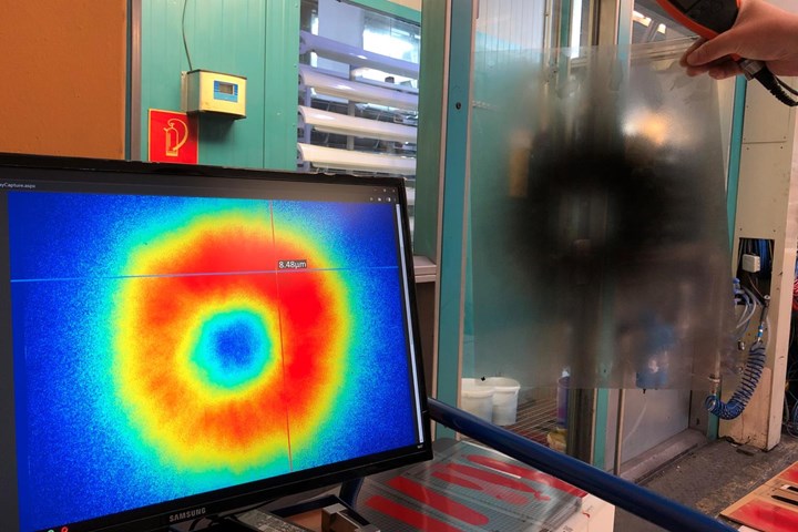
The SprayVision system performs numerical measurements and analysis functions on the captured image, displaying it in a heat map format. Photo: All photos courtesy of Saint Clair Systems.
Perfection in aerospace applications is crucial and the quest for excellence drives down to the finest detail, including the finish on the part. Recently, CFAN (San Marcos, Texas), a supplier of jet engine turbine blades to GE Aerospace, employed the SprayVision system, distributed by Saint Clair Systems (SCS, Washington, Mich.), to investigate the unique traits of its automated blade painting system with the goal of defining a plan to extend First Time Yield (FTY) percentage from <90% to >95%.
Each of the companies in the collaboration brought unique equipment, knowledge, perspective and talent to the problem of automated finishing of CFAN’s various turbine blades.
CFAN, a joint venture between GE Aircraft Engines and SAFRAN, is known for producing the world’s first FAA-conforming composite fan blade, used in various GE Aircraft Engines.
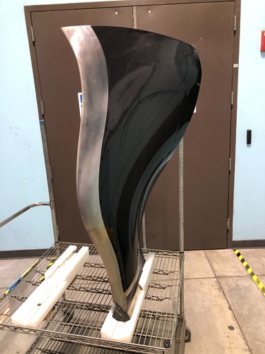
CFAN jet engine turbine blade.
The fan blade exhibits a uniquely complex geometry from the convex to concave side of the component. The application exerts extreme forces on the blade surfaces, so each blade is constructed of a combination of titanium and composites to provide the requisite strength. It poses a significant challenge to bond to these different surfaces while maintaining consistent cured-coating characteristics from side-to-side. The coating must be capable of withstanding a battery of severe tests, including adhesion and rain erosion. This all starts with the primer, making it the logical focus for this exercise.
The primer is a 2K solvent-borne epoxy with a high solids content. The specified viscosity is between 20-50 seconds using a #2 Zahn Signature cup. This elevated viscosity indicates that this is a difficult coating to work with.
CFAN relies heavily upon GE’s engineering specification to determine conformity of the finished coating. It is fair to say that the cosmetic quality of the fan blade is typically better than what you would observe on the exterior of a commercial aircraft.
SCS, a leader in advanced fluid process control strategies and technologies, is focused on controlling and stabilizing viscosity at the point-of-application in industrial fluid dispensing processes. This includes paints and coatings, sealers and adhesives, inks, etc. This is usually accomplished by accurately controlling fluid temperature all the way to the point-of-dispense. In 2020, the company signed on as SprayVision’s exclusive North American distributor.
SprayVision (Ostrava, Czech Republic) was founded in 2017 on the idea of providing a means for paint applicators to literally see the outcome of their painting process before they paint the first part, thus reducing defects and improving overall quality, reducing cost by reducing setup time and paint usage while increasing first pass yield (FPY) to reduce rework, rejects and scrap. The process is not a simulation; it is a measurement of the actual film pattern being dispensed. First introduced at PaintExpo 2018, the technology was voted Best Idea of 2020 out of 171 entries at Vodafone’s Idea of the Year contest.
The Technologies
CFAN automated painting operation is a tightly integrated blend of the most modern control technologies available.
Measuring film pattern
The SprayVision system is built around the SprayCapture Unit. Available in two sizes, the larger A2 system (not shown) is commonly used for bell applications, and the smaller A3 system is for gun spray applications. One of the most innovative features of this capturing technology is that it is designed to accept capture films while still wet, which allows immediate analysis without waiting for the curing process as common in traditional paint quality systems.
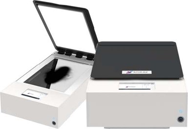
SprayCapture Unit
This capturing hardware is combined with SprayVision software, which performs numerical measurements and analysis functions on the captured image, displaying it in the popular color “heat map” format (see opening photo).
Automated paint system
CFAN’s automated paint system is a tightly controlled, modern robotic conveyorized paint line. The mix room is located directly adjacent to the paint booth to minimize paint travel. The ambient environment in both the mix room and spray booth is tightly controlled by the same make-up air system to assure a consistent 75°F and 50% RH, and the blades are thermally preconditioned to enter the booth at 75°F.
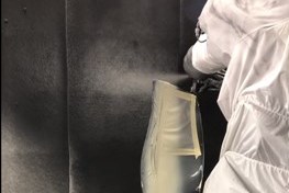
Conveyorized robotic paint application.
The specialized coatings used in this process require that their viscosity be maintained within a very narrow window, which requires dispensing them at a very tightly controlled temperature. This is handled by a temperature control system from SCS.
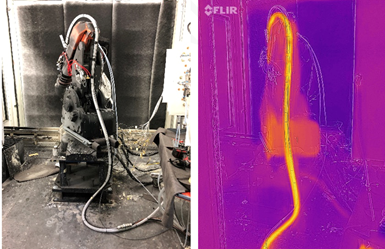
Recorable coax system in place on a robot.
Temperature control
The temperature control function is performed by heat/cool unit combined with SCS’ patented Recorable Coax Hose technology, which extends temperature control to the point-of-application.
Testing and Analyses
Using drawdowns on a special calibration film, the SprayVision Calibration Tool converts the SprayCapture measurements to film thickness measurements.
Establishing the impact of viscosity on paint process outcomes required creating a set of test foils under controlled conditions that match the standard coating parameters used to spray blades, changing only the temperature from 70°F – 120°F in 5°F increments. At each step, the viscosity was measured with the CFAN’s Standard #2 Zahn Signature Cup.
Coating viscosity
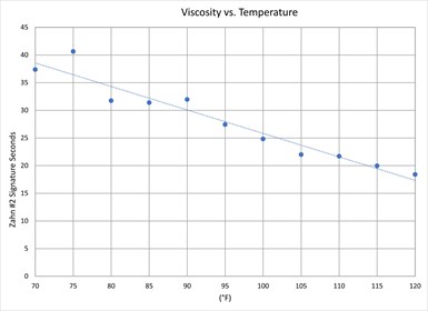
Figure 1: Viscosity vs. Temperature Plot
CFAN established the target primer viscosity at 22 seconds in the #2 Zahn Signature Series Cup. The viscosity change as a function of temperature is shown in Figure 1. CFAN has been running this primer at 100°F.
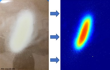
Figure 2: 95°F Static Sprayed Film vs. Captured Color Map View
Static pattern analysis
A static pattern is a brief shot from the gun to establish the spray pattern and droplet distribution. Commonly done on paper, Figure 2 shows how doing this on SprayVision foils makes the characteristics and quality of the spray pattern much easier to interpret. The darker the color, the greater the thickness of the paint in that area.
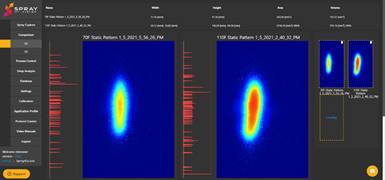
Figure 3: Comparison of 70°F and 110°F Static Patterns
The software can also compare captures as shown in Figure 3. Though all spray parameters are the same, these two patterns are quite different – the result of temperature-based viscosity variation.
Note the different dimensions and distribution of the paint through the patterns.
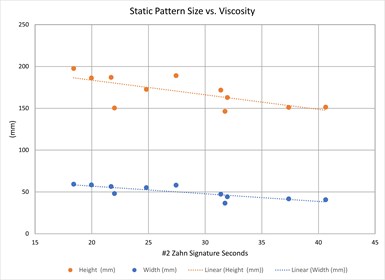
Figure 4: Static Pattern Size vs. Viscosity
Figure 4 shows a 25% change in height which relates to the pattern overlap and will have a significant impact on surface finish if the overlap pattern is not changed to match. Paint distribution through the pattern is another important factor. In both patterns in Figure 3, the distribution of paint is greater toward the top. This may be due to gun alignment, or it could be an imbalance between atomization and shaping air caused by an improper adjustment or an occlusion in the air passages.
The importance of the static pattern is in how the paint is distributed when the gun is moving through its path.
Dynamic pattern analysis
The dynamic pattern puts the static pattern in motion in the form of a single pass across the width of the film.
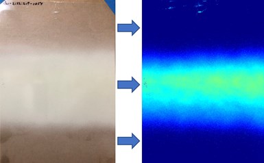
Figure 5: 105°F Dynamic Sprayed Film vs. Captured Color Map View
As shown in Figure 5, it is hard to visually distinguish the important features of the spray pass, however, after capture, the details become readily apparent. The “lopsided” spray, with the concentration of paint shifted to the top of the pattern, will result in striping using a standard 50% overlap.
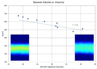
Figure 6: Dynamic Pattern Volume vs. Viscosity
Figure 6 shows the change in pattern volume as a function of viscosity with volume decreasing as viscosity increases. This directly affects transfer efficiency.
Droplet analysis
SprayVision can also capture and analyze patterns at the droplet level. A small, select area is captured and processed with extremely fine detail.
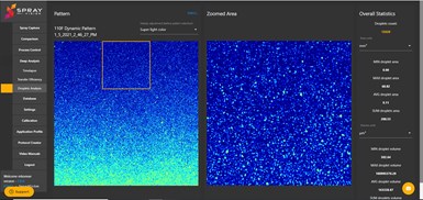
Figure 7: Droplet Analysis in Overspray Area
Figure 7 shows the total Droplet Analysis pattern, with the “Zoomed Area” in the overspray area where the droplets are small and separated.
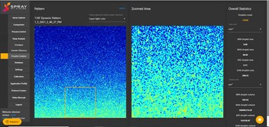
Figure 8: Droplet Analysis in Overspray Area – On the Edge of the Main Spray Area
Figure 8 shows the edge of the main spray area with droplets joining one another to form a continuous film.
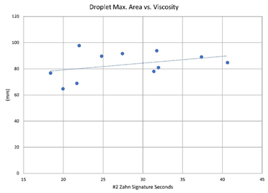
Figure 9: Max. Droplet Size vs. Viscosity
Figure 9 demonstrates that as the viscosity of our paint increases, so does the size of the atomized particles.
Conclusions
The SprayVision System showed the areas where stable viscosity is essential to a predictable outcome. It revealed that a dispense temperature of 110°F produced better primer finish quality than 100°F.
It also identified issues with atomizing and shaping air balance. This is important, because it showed the imbalance of air pressures can produce the same effect as gun misalignment.
It also identified an issue with timing between the air and fluid valves resulting from the air valve location outside of the booth which generates delay and pressure variation at the nozzle.
The findings of this work suggest that utilizing these technologies in the future can produce:
- A 20-30% reduction in paint usage per part
- A two-point improvement in orange peel on the ACT scale
- A 5-7 GU (on a 60° geometry) improvement in gloss
- A 3 - 5% increase in First Time Yield (FTY)
- >2.5% reduction in rework
- Detection of system & equipment failure prior to spraying parts
An expanded version of this white paper is available for download: viscosity.com/hubfs/Aerospace%20Whitepaper-PF%20Online.pdf
Related Content
Multistage Wash System for Continuous Cleaning Efficiency
Gas-heated conveyor parts washing system is said to provide continuous, efficient cleaning throughout the multiple stages of the system.
Read MoreTop Shop’s Journey to Building a Unique Brand
Since this new Ohio plater took over the space and assets of a former plating business, it is intentional about setting itself apart from prior ownership.
Read MoreTop Shop Emphasizes Dedication, Work Ethic
With a primary focus on aerospace and defense work, American Metaseal Corp. of Arbutus, Maryland, has qualified as a Top Shop on multiple occasions.
Read MorePPG, Satys Partner for Aerospace Ecoat System in France
PPG is partnering with Satys, a French industrial group active in aircraft sealing, painting and surface treatment.
Read MoreRead Next
Mitigating Water Condensation
Mike Bonner of Saint Clair Systems discusses how to avoid paint defects caused by condensation resulting from compressed air used for atomizers.
Read MoreA ‘Clean’ Agenda Offers Unique Presentations in Chicago
The 2024 Parts Cleaning Conference, co-located with the International Manufacturing Technology Show, includes presentations by several speakers who are new to the conference and topics that have not been covered in past editions of this event.
Read More





.jpg;maxWidth=300;quality=90)


