Choosing the Right VOC Emission Control Technology
There are many types of VOC emission control technologies out there, but all of them won't be right for you. Knowing the basics behind each technology will help you pick the right one...
Each year, new federal and state environmental regulations require higher destruction and improved capture of volatile organic compounds (VOCs). The coating industry and VOC control equipment manufacturers must develop technologies to meet these regulations while providing improvements in both capital investment and operating costs. A variety of auxiliary pollution control approaches are currently available. It is important to understand the features, benefits and potential drawbacks of the different types.
Solvent recovery
Adsorption is defined as the concentration of a substance (adsorbate) into the surface of a solid (adsorbent). The basic principles of adsorption are applied to air emission control when a solventladen air stream passes through a bed of high-surface-area solids material (typically carbon, alumina, silica gel or molecular sieve) and is “captured” or adsorbed into the surface of the material. Once the micropores of the adsorbent material are filled to capacity, the process stream is then directed to another bed of adsorbent while the original bed is “desorbed.”
Desorption, also referred to as regeneration, is a secondary process whereby solvent is removed from the adsorbent by passing high-temperature steam or other gases through it. The highly concentrated solvent air stream then goes through a condenser and a separation or distillation column where the solvent is separated or recovered from the air stream condensate.
Characteristics:
- High capital investment
- Moderate operating cost
- 95-98% removal/destruction efficiency
- Maintenance intensive (steam, condensing and distillation systems, activated carbon material)
- High maintenance cost (replacement or regeneration of carbon material)
- Additional refining necessary if using multiple solvents
- Wastewater quality must be monitored for disposal/treatment purposes
-
Potential of solvent to be reused or sold
Thermal oxidation
Thermal oxidizers are typically used to convert hydrocarbons into carbon dioxide (CO2) and water (H2O) through oxidation. This process is carried out by raising the temperature of the process exhaust to break the hydrogencarbon bonds, which allows new bonds to form, creating CO2 and H2O. When this occurs, an exothermic reaction takes place, and heat is released.
Oxidizers typically are designed with a 0.5 sec or greater total residence time. Residence time is critical, not for the oxidation reaction, but for proper mixing. Many designs fail to complete the mixing in the time available. In this instance, to meet a performance specification, more fuel must be burned than would be needed if mixing were complete.
Nitrogen oxides (NOx), products of combustion, increase as temperature and fuel inputs increase. NOx output should be considered because it is a primary component in the production of ozone.
Regenerative thermal oxidizer
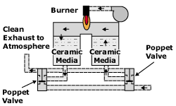
Regenerative systems (see Figure 1) are thermal oxidizers that operate at high temperatures, up to 1,500-1,800F. These systems use a ceramic stoneware or other heat exchange media. In most designs, the media is mounted in vertical columns. The process air stream is passed through a column of media as it enters the oxidizer. The air stream is heated further to oxidation temperatures by a burner in the central combustion chamber. The air stream then exits the oxidizer through a second media column. The second column “stores” energy from the hot air stream. By constantly cycling the air stream between the columns, the incoming air stream is heated by the media, which in the previous cycle was absorbing heat from the air stream exiting the central chamber. As this column loses heat to the incoming air stream, it cycles and becomes the receptor of heat, repeating the cycle. The theory is quite simple and has proven to be successful in many applications. Regenerative thermal oxidizers can be designed with one, two, three or more columns.
Characteristics:
- Moderate capital/installation costs
- High thermal efficiencies
- Low operating cost
- Moderate to high destruction efficiencies (95-99%)
- Higher radiation losses due to system surface area
- Best for low concentrations of VOCs in the process exhaust with high-volume exhaust flows
-
Heavy weight requires additional installation support
Recuperative thermal oxidizers
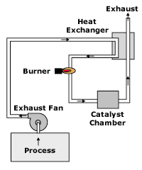
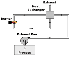
There are a number of recuperative thermal oxidizer designs that can be used to destroy VOCs. The diagram of the thermal oxidizer shown in Figure 2 is a simple design that passes air through an airtoair heat exchanger to preheat it before entering the burner chamber. In the burner chamber, the process exhaust air is heated to a sufficiently high temperature and held at this temperature with some degree of turbulence to ensure VOC destruction.
Thermal oxidizers clean process air streams by burning or oxidizing them at high temperatures. Typical VOC reduction is 99%. Carbon monoxide (CO) can be either created by the partial oxidation of VOCs or destroyed by the complete oxidation of CO to CO2 in a thermal oxidizer, depending upon operating temperatures. CO production tends to rise with increasing temperature until it reaches a maximum at about 1,200F. Above this temperature, the CO content tends to decrease rapidly. At 1,400F, CO emissions from thermal oxidizers are relatively low.
Characteristics:
- Moderate to high capital/installation costs
- High operating cost at low solvent loading
- Destruction efficiencies can be very high (greater than 99%)
- Need high operating temperatures (1,380-1,500F) to get low CO levels
- NOx formation, especially at operating temperature above 1500F
- High exhaust gas temperatures (secondary energy recovery is possible and high-temperature exhaust stack construction is required)
-
Quality materials of construction necessary for longevity
Catalytic oxidation
Catalytic oxidizers (see Figure 3) are an alternative to thermal oxidizers for oxidizing gaseous, combustible contaminants into carbon dioxide and water. Their successful operation is limited to a more restricted range of applications than thermal oxidizers. But, where applicable, catalytic units offer the potential of significantly lower fuel consumption and operating costs plus reduced CO and NOx emissions. The basic elements of the catalytic unit are a preheat/mixing section, designed to achieve a uniformly preheated and distributed waste stream flow, and the catalyst bed or catalyst matrix, where the majority of the oxidation reactions take place.
The oxidation of most hydrocarbons and carbon monoxide with catalysts occurs rapidly in the range of 300-900F. With thermal oxidizers, the oxidation reaction requires a high temperature, 1,200-1,600F, to break the carbon, hydrogen and oxygen bonds.
Besides reduced energy consumption, NOx emissions from catalytic units are very low because of the lower oxidation temperatures as well as the lower burner firing rates. In addition, the oxidizing nature of the catalyst results in very low CO emissions. However, there are tradeoffs involved to gain these advantages. Catalytic oxidizers can be subject to masking agents or poisons that inhibit the effectiveness of the catalyst.
Catalytic systems are limited to applications in which the waste stream has negligible particulate loading and/or “poisons” that can reduce the effectiveness of the catalyst. These poisons are primarily silicon and phosphorus, which coat the catalyst; halogens, such as chlorine, which directly attack the active metals converting them to an inactive form; and sulfur, which inhibits the activity of some catalysts. The oxidation activity of the catalyst can also be reduced by the loss of active components through attrition, deposition of unreacted VOCs (coking) onto the catalyst surfaces or sintering of the catalyst (collapse of the catalyst structure caused by high temperatures).
Regenerative catalytic oxidizers
This oxidizer is similar in design to the regenerative thermal oxidizer. The addition of catalyst to either the media or the top of the media column allows lower operating temperatures. Depending on component design, this unit could be operated as a thermal oxidizer after catalyst degradation.
Characteristics:
- Moderate to high capital/installation costs
- High thermal efficiencies
- Low operating costs
- Very low levels of CO emission
- Very little or no NOx formation
- Best for low-VOC, high air flow applications
New developments
This section discusses some recent developments in catalytic and regenerative thermal oxidation technology.
Catalytic oxidizers. Noble metal catalysts require inlet temperatures above 600F to achieve more than 98% VOC conversion. Given that the maximum exhaust temperature is 200300F, the exhaust gases from these applications need to be heated to the desired operating temperatures to generate significant supplemental fuel use. A catalyst that functions at a lower temperature would lower the operating cost by reducing the need to heat the process system.
A catalyst formulation has been developed that reduces the lightoff temperature for oxygenated hydrocarbons. Figure 4 compares the lightoff curves for this catalyst with a commercially available noble metal catalyst. Reactors with the new catalyst can operate at temperatures 100-200F less than reactors containing conventional catalysts.
Regenerative thermal oxidizers
RTO systems have emerged as the leading technology because of their high heat recovery, which produces an outstanding operating cost advantage in comparison to other technologies while maintaining high flexibility in the types of processes that can be treated. Typically these systems are very large, requiring expensive installation work. Development efforts have focused on a compact, modular and cost-effective RTO for the low flow VOC control market.
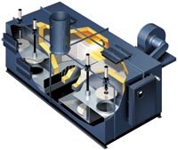
There are some distinguishing features of these RTOs (see Figure 4):
- Oxidizers are designed such that flow-directing poppet valves are incorporated into the oxidizer shell to minimize the oxidizer footprint and fabrication costs. This feature eliminates the transition ducts that have been associated with traditional designs and further minimizes the field installation.
- Oxidizers are modular and designed to ship as completed assemblies with width dimensions that will comply with commercial trucking equipment without special shipping considerations or permits. These oxidizers are completely preassembled, including all control panels, piping, conduit and electrical wiring. This preassembly minimizes the installation effort and maximizes quality control over the finished product.
- Oxidizers undergo simulated run conditions, control systems check out and calibration prior to shipment to facilitate shorter startup times.
- Oxidizers feature stateoftheart controls, including modems to enable the use of telemetry. Through the use of telemetry, product support and oxidizer uptime is maximized while field service requirements are minimized.
- Oxidizers are designed with minimal entrained volume for a design destruction efficiency goal of 98% without capture of the VOCs exhausted during the poppet valve switch.
-
All oxidizers are designed to accept optional VOC capture vessels when destruction efficiency requirements exceed 98%. The design will permit oxidizers to be upgraded in the field if the end user requires.
Choosing the right technology
Which of these new technologies is best for a specific facility? The answer can be difficult or easy, depending on the approach you take in the evaluation process. The best approach is to find vendors that offer the best technology available based on your production requirements.
Find a supplier that offers multiple control methods and works with you to determine which technology is best for your requirements. This way you can be sure you are purchasing the best system for your needs. For the vendor to assist you in making the correct selection, you first need to accumulate some critical data. The minimum data required for proper technology selection are the following:
- Number of sources;
- Uptime and annual hours for each source;
- Flow rates from each source (scfm);
- Typical VOC loading from each source (lb/hr);
- Composition of the process stream (such as VOCs and catalyst poisons) used in your facility;
- Utility costs;
- Facility layout, identifying sources, utility connections and special limitations that could affect location of the oxidizer; and
- Regulatory requirements for your facility (make sure you comply with federal, state and local regulations).
With the data, a request for quotation (RFQ) can be sent to a number of qualified vendors. A vendor should have the appropriate technologies in its product mix and the financial ability to stand behind what it offers.
Guidelines for choosing
When evaluating the options, include operating, installation and capital costs. Capital and operating costs should be based on the actual utility costs, uptimes and annual operating cycles of the facility. It might be best to develop a chart listing flows and annual hours for each source.
Request a spreadsheet showing the features for the proposed system to ensure you are making an apples-to-apples comparison. Most reputable vendors should be able to provide this as part of their evaluation.
Request delivery lead times for the system to ensure that the facility can meet the regulatory timetable.
Request references from the vendor and contact them to determine the accuracy of the vendor’s claims. The references should be similar in size and scope to your facility.
Vendors can determine which technology will best fit your needs and regulations. While a certain system may appear to be the ideal system for your needs, the expertise of reputable vendors that offer a broad range of products should help you decide between a low temperature catalytic oxidizer, a regenerative thermal oxidizer or another system. Local regulatory requirements, product limitations, uptime, utility costs or facility limitations may all play an important role in determining which technology is best for your facility. Working with a reputable vendor and supplying proper data in the RFQ can help you select the best technology for your company.
Schematic of new type of RTO
- Schematic of regenerative thermal oxidizer
- Schematic of recuperative thermal oxidizer
- Schematic of catalytic oxidizer
- Comparison of light-off curves
Read Next
Delivering Increased Benefits to Greenhouse Films
Baystar's Borstar technology is helping customers deliver better, more reliable production methods to greenhouse agriculture.
Read MoreEducation Bringing Cleaning to Machining
Debuting new speakers and cleaning technology content during this half-day workshop co-located with IMTS 2024.
Read MoreA ‘Clean’ Agenda Offers Unique Presentations in Chicago
The 2024 Parts Cleaning Conference, co-located with the International Manufacturing Technology Show, includes presentations by several speakers who are new to the conference and topics that have not been covered in past editions of this event.
Read More




.jpg;maxWidth=300;quality=90)


