Defects in Hard Chromium Deposits Part II: Detection, Prevention and Repair
Most defects in various hard chromium deposits arise from defects in the basis metal. These defects may be in the original metal surface or may be caused by preplate finishing. Homogeneous hard chromium deposits can be produced only by eliminating these defects. The final segment of this article describes visual and provocative methods of detecting defects. Also discussed are prevention techniques and repair operations.
by
H. Chessin, E.C. Knill and E.J. Seyb, Jr.
M&T Chemicals, Inc., Research Laboratory, Rahway, New Jersey, USA
Editor’s Note: Originally published as H. Chessin, E.C. Knill & E. Seyb, Plating & Surface Finishing, 70 (3), 52-57 (1983), this is the second of a two-part paper based on a presentation given at AESF SUR/FIN 1981 in Boston, Massachusetts. This paper won a Silver Medal for Outstanding Paper published in Plating & Surface Finishing in 1983, which was presented at SUR/FIN 1984 in New York, New York. A printable PDF version is available by clicking HERE.
ABSTRACT
The final segment of this article describes visual and provocative methods of detecting defects. Also discussed are prevention techniques and repair operations.
Inadequate preplate mechanical surface finishing is one of the most common causes of defects in hard chromium deposits.1 And because almost all workpieces are machined, ground or honed prior to plating, it is important that these operations be carried out properly to minimize defects.
Inspection of the basis metal is the first line of defense against defective deposits. Sound inspection procedures are probably the least costly insurance for the plater to protect himself against both costly rework and misunderstandings with his customer or quality-control personnel.
So, before discussing the science of repairing defective hard-chromium deposits, it is imperative to understand and appreciate methods of inspection and detection.
Inspection
The type and degree of inspection depends on the following factors:
- The size, volume and value of the parts.
- Specifications for the plated product.
Particularly on large parts, one of the most satisfactory and least costly inspection systems requires that each operator examine his own work. Thus, the grinder, polisher, blaster or honer will not spend valuable time finishing a defect-exhibiting workpiece detrimental to the final product. Similarly, the degreaser, racker and plater all have an obligation to spot defective surfaces and poor workmanship, and, most importantly, to report them.
The plater's inspection is of paramount importance because it is the last before the finish is applied. If he can pinpoint a defect that might cause the plated work to be rejected, he will have saved the cost of plating, stripping, refinishing, re-stopping off, and re-racking. Even more important is the possible erosion of customer goodwill, the loss of valuable production capacity, and the delay in processing other work. All of these drawbacks could be avoided if management or the plating department would insist on thorough inspection immediately before electrodeposition.
Not all defects can be spotted with the naked eye, so it is sometimes necessary to resort to tools or special procedures such as:
- Visual inspection without magnification but under good light.
- Inspection with low-power magnification.
- Microscopic examination of critical or suspicious areas. (For example, engraved rolls and plates are normally inspected microscopically before plating to detect the presence of ink or defects.)
- Magnetic particle inspection" for cracks.[1]
- X-ray inspection, primarily for weld assessment.
- Ultrasonic flaw detection,[2] chiefly for sub-surface voids and laminations.
- Dye-penetrant examination to expose pits and cracks (several commercial products are available).
- Etching to detect cracks (see "Provocative Detection Methods").
- Hydrogen charging to detect blisters and lamination (see "Provocative Detection Methods").
- Checking for pits or cracks by noting dark bleedout spots as the work dries after degreasing, alkaline cleaning, acid pickling or electrolytic etching.
- Measuring to determine surface roughness.
- Examining after polishing, buffing, vapor blasting or fine-grit blasting.
Some of these inspection methods involve very little extra work, can be performed routinely at minimal cost, and may be properly included in the plating price. The cost of those methods that require special equipment, significant time, or the services of an outside testing laboratory must be billed separately from routine plating charges.
There is no reason for the plater to be in an adversary relationship with his customers or management because he receives work containing basis-metal defects. The finishing department can supply invaluable inspection service to either party and can recommend preventive measures and pragmatic solutions to problems at hand. The reward for the plater may be additional work and the payment of higher prices for these services.
If surface pits, pores, cracks, laminations or inclusions are observed, the plater is faced with the problem of what to do about them. The answer is often complex. It will depend upon his experience with his customer, his knowledge of the finishing requirements, the chromium plating process and how it will respond to the defects, his experience with the basis metal and type of imperfection, and, finally, his ability to employ the various repair techniques.
The four-step procedure outlined below usually is useful in making the decision of how to proceed.
- Notify the customer or QC department of abnormalities in the finish or product appearance and solicit advice.
- Learn the history of the parts in question. Perhaps they represent reworked rejects, work produced after a change in the basis-metal specification or supplier, a different processing procedure, new equipment or a just-hired operator. Perhaps the parts have corroded at some point in the processing sequence and the defects are residual pits. The goal is to eliminate the problem immediately at the source of the defects.
- Plate a test piece to determine whether the defect is detrimental to the deposit, in many cases, the defect does not affect the utility of the finished part.
- Select and evaluate a repair technique.
The simplest and best procedure when dealing with defective batches of small parts is often to test plate some of them. With the knowledge gained from this test, it is possible for the plater to either proceed or notify his customer that he has a specific problem. When only one part or a few large or costly ones are involved, it is generally unwise to spend time and money to plate the work without the customer's knowledge and acceptance of the risks involved. The same advice would apply to Item 4 above, unless previous experience with the customer, his work or an identical job has proved that the repair technique is acceptable and poses no risk when properly performed.
Provocative detection methods
When the value of the work and the costs of preparatory and finishing operations are high, or when the specifications for the completed work are rigorous, it is unwise for the plater to depend solely on superficial methods of defect detection. Visual inspection of the surface, even with the advantage of high-power magnification, will not reveal gas pits or blisters that may lay just below. Tightly closed cracks may open when the work is heated in cleaners or in the plating tank - especially when hydrogen gas permeates the metal seeking out every void. For this reason, it may be necessary to test the surface by one of these provocative techniques:
- Anodic electrolytic etching in chromic acid or sulfuric acid.
- Chemical etching in hydrochloric, sulfuric or nitric acid.
- Cathodic charging the work with hydrogen in sulfuric or chromic acid without catalyst.
Anodic etching is least destructive and has the advantage that it may be performed as part of the plating cycle. The work is subjected to at least 30 sec but not more than 5 min of anodic etching at about 15 A/dm2 (1.5 A/in.2) in 10 to 15 vol% sulfuric acid at 21°C (70°F), or in a chromic acid solution (225 g/L or 30 oz/gal) at 54°C (130°F). Following etching, the work should be rinsed in a suitable reclaim tank. It may then be rinsed in hot water to speed drying and permit rapid inspection. If no defects are found, the work should be re-etched briefly to remove any flash rusting that may have arisen during inspection, then plated in the normal manner.
Anodic etching is fast, inexpensive and effective in revealing small pits or cracks hidden by smeared metal from mechanical finishing. The defects are especially visible during the drying process because the bleeding of acid or rinse water from the pits or cracks reveals their location quite clearly. These areas should be identified with chalk or a marking pen to make sure they are not overlooked when repairs are made.
While the anodic etching technique is satisfactory for most ferrous alloys, care must be taken not to passivate alloys such as high-tungsten tool steels that cannot tolerate anodic acid etching, or to overetch any metal without refinishing the surface to remove any weakened metal. Unlike the other methods, anodic etching does not introduce hydrogen into the metal prior to plating, if sulfuric acid is used in the preplate cycle, great care must be taken to prevent its dragover into the chromium plating bath.
Chemical etching may be performed conveniently after the initial cleaning of the work and before stopping-off or racking. It should not be used on oily or greasy surfaces. Because hydrogen is generated, it is essential to bake all work with a hardness above Rockwell G-35, after etching, to remove hydrogen.2,3 Hydrochloric acid (20 to 50 vol%) at room temperature, sulfuric acid (10 vol%) at 50-60°C (122-140°F), or nitric acid (5 to 10%) at room temperature all are suitable for exposing hidden defects. Care must be exercised to protect critical surfaces not being tested. Stop-off lacquer or plater's PVC tape usually are satisfactory for this purpose.
Cathodic charging is used primarily to expose defects in roiled steel plate or on products fabricated from rolled or drawn steel. The procedure consists of cleaning the work, then racking it as for plating. The work next is made cathodic at 15 to 45 A/dm2 (1 to 3 A/in.2) for 4 to 24 hr, depending on the thickness of the steel plate, in either the chromic or sulfuric acid solutions at 55-60°C (130-140°F). The higher charging temperature expands both the crystalline structure of the metal and the defects, thus greatly accelerating the rate at which hydrogen is introduced to the basis metal. While the atomic hydrogen can move freely through the crystalline lattice structure, it cannot form molecular hydrogen until two or more atoms can rendezvous in a void or defect in the steel. When this occurs, enormous pressures are built up in the defect, causing the defect or void, which has been rolled flat, to expand. This creates a bulge or blister on the work surface if the void is near. Some blisters may burst, but most will appear as small bumps on the surface. They can be exposed even more clearly for inspection by either slack belt polishing or hand "sanding" the surface with a well-worn, fine-grade aluminum oxide belt (e.g., 240 or 320 grit). Each defect should be marked at this time to ensure it is not overlooked during the repair procedure.
It may seem wasteful to provoke defects, which must then be repaired, but bear in mind that chromium plating produces effects similar to those from a hydrogen-charging test. When the cost of failure is high, it may be much cheaper to expose and correct all possible defects before plating than afterward. In fact, it may be possible to perform this test on a piece of rolled plate, cropped from the area that was the top end of the billet before the plate was fabricated. At this point, the costs of the test are minimal because the defects, if found, need not be repaired. If blisters do not develop from such a test plate, the material from which it was cropped can be assumed to be essentially clean and relatively free of basis-metal defects. These tests permit the selection of especially high-quality plate for fabrication into large rolls or drums that must be chromium plated.[3]
Repair of basis metal
After detecting basis-metal defects and determining that they must be corrected and that the customer or management will pay for all repair work, the plater must select the best means of reparation. Among these are dot welding, plugging, welding, sealing, and resin-filling.
Dot welding
The least expensive and usually the fastest of the various basis-metal repair methods is dot welding. Skilled workmen can perform 20 to 40 such repairs per hour. For most ferrous alloys other than the stainless steels, a low-carbon steel ball is preferred. For stainless steels or chromium-plated surfaces, a 410-grade SS ball is recommended. Pure nickel balls are required for welding on nickel electrodeposits.

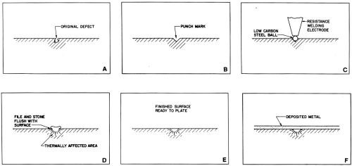
Figure 1 - Steps for repairing basis-metal defects using dot welding.
When repairing some high-strength or hardened dies and molds, it may be advantageous to use a ball of an alloy as similar to the basis metal as possible. Either 1.5- or 3.0-mm-diameter (0.062- or 0.125-in.-diameter) bails are adequate for most repairs. The welding operation is performed with a low-power electrical resistance welder.[4] The repair procedure is as follows:
- Prick-punch or grind a small depression to remove the defect (Figs. 1a and b).
- Place the ball in the depression.
- Electrically ground the work to the welder.
- Place the electrode firmly on the ball (Fig. 1c) and press the switch (Fig. 1d). The current and timer settings must be selected prior to welding by determining the correct transformer setting for the bail size on a test piece. The same current normally can be used with the same ball diameter.
- File the weld close to the surface using a "safe" file (i.e., a smooth, diagonally cut file with taped or rounded edges).
- Finish the weld by smoothing it flush with the surface (Figs. 1d and 1e) using a strip of aluminum oxide cloth wrapped around a smooth file or with an appropriate hand stone - each with rounded edges. The stone or abrasive covered file should be held at an angle of 45 degrees to the direction of the grinding or polishing scratches; the motion of hand finishing should be in the direction of the grinding pattern. Usually, 120-grit abrasive is satisfactory. A relatively coarse abrasive removes the weld quickly and a finer abrasive can then be used to remove the original scratches if necessary.
- Inspect with a 10X magnifying lens to be sure the weld is free of pits or cracks. If the weld is not perfect, repeat the process.
- Repolish the entire repaired area to remove all traces of scratches from hand polishing.
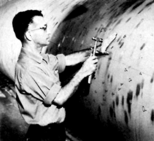
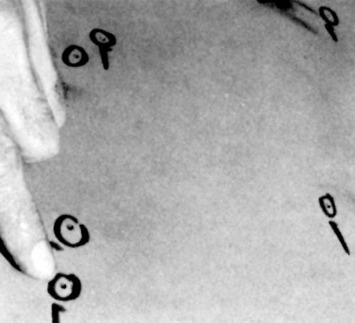
Figure 2 - Plugging defects in the surface of a large cast-iron drum.
Plugging
This procedure is more costly and slower than dot welding (10 to 30 plugs/hr in "soft" metals with noncritical finishing requirements) but is capable of providing perfect repairs consistently. It can be used on all ferrous (Fig. 2) and most non-ferrous basis metals. Oil hardening drill rod plugs are suitable for all non-stainless ferrous alloys. Precision ground cold-rolled steel may be used for very large plugs (e.g., larger than 6 mm, or 1/4 in., in diameter). Stainless-steel rod of the same grade as the basis metal is preferred for SS alloys. Phosphor-bronze rod is the best selection for plugging copper and most copper alloys because of its stiffness and desirable malleable characteristics. Hard-drawn copper wire or rod may be used in large sizes if desired, but it may be too soft to use for holes smaller than 3 mm (0.125 in.) in diameter. Hard drawn pure nickel wire (grades 200 or 201) should be used for repairing nickel electrodeposits. The procedure for plugging any basis metal is as follows:
- Prick-punch the defect and drill a hole approximately 5 to 2.5 times the drill diameter in depth (Fig. 3). The ratio of depth to diameter decreases with increasing diameter. For example, a hole diameter of 6 mm (0.25 in.) requires a ratio of only 0 to 1.5. Most plugging is performed with Drill #'s 52 through 30, ranging in diameter from 6 to 3.26 mm (0.0635 to 0.1285 in.). Although plugs as large as 12.5 to 19 mm (0.5 to 0.75 in.) have been used successfully, they are rarely required.
- Fit an appropriate rod, one drill size smaller than the tool, into the drilled hole loosely in such a manner that it rests firmly against the bottom. The hole must be clean, without any debris. The edge at the surface must be uniformly sharp and free of burrs. The end of the rod inserted into the hole must be fiat or tapered to the shape of the drill point (Fig. 3c).
- Snip or saw the rod about 6.4 to 12.7 mm (0.25 to 0.5 in.) above the surface and file the end flat.
- Swage the rod tightly into the hole with a series of firm hammer blows. A 2- to 4-oz ball peen hammer is large enough for the commonly sized rods. It is essential that the hammer be heavy enough to transfer the force of the blow through the rod to the bottom end, which must expand first if the hole is to be completely filled by the plug. The space provided by the slightly loose plug permits all air to escape as swaging progresses (Fig. 3d).
- If necessary, shorten the length of the rod that extends above the surface, before swaging is complete, to avoid bending the plug and to provide a perfectly tight seal between the plug and the basis metal at the surface.
- When swaging is complete, cut the rod off close to the surface and file it as close as possible with a "safe" tool. Finally, smooth the rod flush with aluminum oxide cloth on a file or with an abrasive hand stone as described under the section on dot welding.

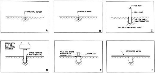
Figure 3 - Steps for repairing basis-metal defects by plugging.
Large plugs are occasionally "fitted" by shrinking them in dry ice or liquid nitrogen and dropping them into holes drilled slightly smaller than the plug, usually 0.025 to 0.037 mm (0.001 to 0.0015 in). The plug must be left slightly longer than the depth of the hole so that it can be peened and finished in the manner described above after the plug was fully expanded. Very large plugs may be threaded and screwed into tapped holes that have been counterbored to remove the top two or three threads. The plug or rod should be threaded for a distance just long enough to fit firmly in the bottom of the hole. The unthreaded portion of the plug then may be cut off slightly above the surface after the rod has been screwed tightly into the hole with a pipe wrench. The unthreaded end must fit the counterbore snugly. The plug then may be swaged tightly into the hole. It is customary on large threaded plugs to insert a small plug in the edge of the large one. This dissects the circumference of the plug and acts as a key to lock it securely. The method may be useful in filling unwanted holes drilled inaccurately or made obsolete by design changes.
Welding
Large cracks, deep blisters, defective welds, large damaged areas and similar defects often can be repaired by heliarc or submerged arc welding. The welder should be certified and licensed to repair high-pressure vessels. The work should be prepared for welding by grinding out the defect. This type of repair must never be undertaken by a plater without the full knowledge and approval of the customer or the metallurgical and engineering departments.
Brazing or silver soldering may be used successfully on copper and copper alloys but is not recommended for repairs to ferrous alloys unless they are to be plated with a seal coat of 0.025 to 0.05 mm (0.001 to 0.002 in.) of cyanide copper before chromium plating.
Sealing with undercoat
It may be cheaper to apply a suitable undercoat of copper, iron, nickel or chromium beneath the final layer of chromium if the basis metal is very porous, as typified by some cast metals, sprayed metallic coatings or components formed by powder metallurgy.
Electrodeposited copper is suitable for sealing many non-ferrous basis metals, and has been used successfully on a variety of ferrous castings or porous steel components not subjected to severe pressure or stress. A cyanide strike must be used to cover ferrous base metals; thereafter, an acid copper sulfate bath is employed to fill minute pits and pores because of its excellent microthrowing power. Typical thickness may range from 0.075 to 0.75 mm (0.003 to 0.030 in.). The heavier copper deposits are usually precision ground before chromium plating to avoid distorting the contours of the work and/or cutting through the chromium as it is being finished. Typical applications for copper undercoats include conductor rolls for continuous strip plating and printing rolls and plates. Copper is not recommended as an undercoat for tools, dies, bearings or most hydraulic applications.
Iron and nickel are also considered excellent undercoatings for functional chromium deposits. The undercoatings must be deposited from physically clean, chemically pure plating baths without brighteners. Both Watts and sulfamate nickel baths are used successfully. Iron may be plated from the chloride, sulfate or mixed chioride/sulfate baths. Deposits usually range from 0.13 to 1.3 mm (0.005 to 0.050 in.) although a minimum of 0.25 mm (0.010 in.) should be deposited on roils and other simple shapes to seal most of the porosity. Obviously, any decision to utilize an undercoating must include dimensional clearance for the extra deposit thickness before plating. The cost of such an undercoating is frequently insignificant when compared with the value of the work being plated. The porefree finish obtainable by this type of repair is not achievable by any other means at a comparable cost.
Resin filler materials
Very porous basis metals are sometimes filled with a suitable resin prior to chromium plating. Vacuum impregnation with epoxy or polyester resins may be beneficial for sealing pores in sprayed or powder formed metals. The technique is limited to relatively small articles, due to the requirement that they be completely evacuated in a vacuum chamber. When the pores have been filled and the resin has set, the excess resin must be removed from the surface by polishing or grinding. Because the open pores are completely sealed, hydrogen gas cannot be evolved. Chromium will readily bridge the nonconductive steel resin if the width of the defect is significantly smaller than the thickness of the deposit. Figure 4 shows a defect that is wider than the thickness of the deposit and that has been partially plated over with chromium. The possibility of having bleed-out or staining problems will be either eliminated or greatly reduced.
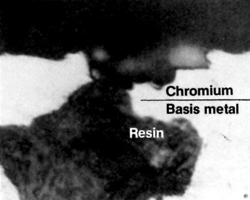
Figure 4 - Chromium deposit partially bridging a resin-filled void.
There are metal-filled resins on the market that may be of some value for filling small voids before chromium plating. However, the strong oxidizing action of chromium plating solutions will attack many otherwise chemically resistant resins. Therefore, most metal-filled resins are better suited for use prior to depositing undercoatings of copper, nickel or iron than for direct deposition of chromium. The technique must be limited to very small defects to avoid the presence of inadequately supported chromium. If the area is sufficiently small (e.g., less than 0.13 mm, or 0.005 in., in diameter) the chromium will withstand normal thermal and mechanical stress without failure when plated at a thickness greater than 0.13 mm.
Repair of plated deposits
In spite of careful basis-metal preparation and clean, well-balanced plating solutions, defects occasionally appear in the finished work. Improper handling of a plated part in the customer's plant or in the plating shop, or an accident in the functioning of a component in service, may result in a minor defect on an otherwise perfect chromium-plated surface. The cost of removing a large part from service, plus the expense of stripping and completely refinishing, makes local repair of the damage or defect a very attractive alternative.
To be able to make satisfactory local repairs adds an important new dimension to a functional-chromium plater's capabilities. It provides a relatively inexpensive, usually completely satisfactory method of puffing the part back into service with a minimum loss of production. It also offers a superior technique of providing flawless surfaces by permitting repairs to a preliminary deposit of chromium, which can then be given a final flawless deposit. The repair of finished surfaces requires highly developed skills because the possibility of accidental damage during processing prevails. The procedure for repairing a pit originating in the basis metal of a chromium-plated surface is summarized below:
- 1. Protect the surface not involved in the repair from mechanical and chemical damage.
- 2. Grind the defective area to the basis metal, using a small high-speed hand grinder with an aluminum oxide ball point, 3 to 6 mm (1/8 to 1/4 in.) in diameter, or a suitable conical abrasive point. The initial grinding may be performed with a relatively coarse abrasive, but it may be necessary to finish with a fine grinding point or a cloth abrasive wheel. This will produce a sufficiently smooth surface so that the defect can be seen when the basis metal is exposed. A change in the sparks from the bright white of chromium to the distinctive yellow or orange spark of a ferrous metal will reveal the exposure of steel. For confirmation, the ground depression may be wiped with a mildly acidic solution of copper sulfate. Copper will deposit by immersion on any nonstainless ferrous alloy, clearly showing the extent of the exposed basis metal. A dial type depth gage, divided into units of 5 or 5.0 μm (0.0001 or 0.0002 in.), and mounted in a V-block, can be used to measure the depth of the hole from the plated surface or the deposit/basis-metal interface. If the defect is quite shallow (less than 0.08 mm, or 0.003 in.), it may be removed by grinding. If the defect obviously cannot be removed at this depth, it is usually advantageous to repair the defect by plugging or welding before attempting plating.
- 3. After the repair has been made and the plug or weld has been ground flush with the surface of the basis metal, shape the edges of the chromium by grinding with a 3-mm-diameter (1/8-in.-diameter) ball point or cylindrical stone to provide a contact angle of approximately 60 degrees between the basis-metal surface and the wail of the depression (Fig. 5). The purpose of providing this steep angle is to minimize the breadth of the exposed interface between the original deposit and the repair deposit. Because the surface is etched for better adhesion before the repair layer of chromium is applied, a low angle (e.g., 15 degrees) will show an unsightly (etched) ring after the final grinding step.
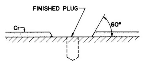
Figure 5 - Repaired surface prior to spot chromium plating.
- 4. Carefully inspect the area to be plated with a 10 or 20× magnifier to be sure that no pits or imperfections remain. The area surrounding the prepared spot should be washed thoroughly with lacquer thinner and masked with a thinned (50%) stop-off lacquer. The thinned prime coat is then followed by several layers of unthinned lacquer. The area of each spot to be plated must be measured carefully by tracing the spot on 1.0-mm (0.1-in.) square-grid graph paper or by checking the area against the size of a dowel that will just cover it. The areas must be recorded for use in calculating the plating current to be used.
- 5(A). Construct a cell with either PVC plastic pipe, vinyl plastisol-coated steel, a well-lacquered paper cup (or ice cream carton), or by welding sheets of PVC plastic. A single spot cell normally would measure 7 to 12 cm (3 to 5 in.) in diameter. The bottom of the cell must be carefully fitted to the contour of the work surface by shaping it against a piece of coarse abrasive cloth taped to the surface. The bottom edge of the cell must then be coated with thinned (50%) lacquer. As soon as the lacquer is dry, the cell is centered over the stopped-off area and lacquered to the work surface with several coats of unthinned lacquer applied to both the inner and outer edges of the cell and adjacent lacquered surface (Fig. 6).
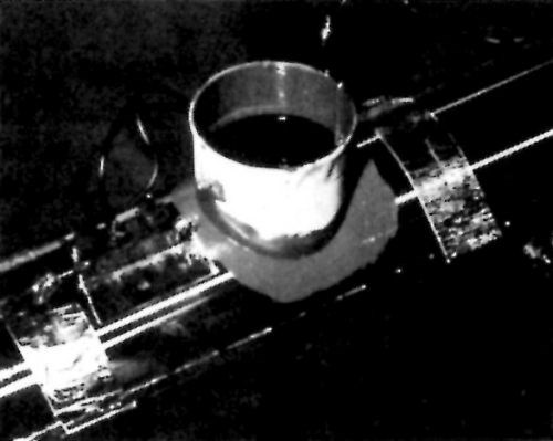
Figure 6 – Cell with surface thermostat and strip heaters ready for local repair by plating.
- 5(B). An alternate type of cell is a permanent unit containing an anode, inlet and outlet connections through which plating solution may be pumped. The cell is fitted with a resilient gasket of Viton[5] or Hypalon[6] to make a liquid-tight seal when the cell is clamped tightly against the work. The gasket can be provided with a hole shaped precisely to fit the area to be plated or it can be oversized and applied to a surface stopped-off as described in Step 5 above.
- 6. Heat the work surface. Hollow parts such as drums and many rolls can be heated by flowing steam or hot water through them. The surface also can be heated by the application of electrical strip heaters, in any event, it is advisable to control the temperature of the surface automatically with surface-mounted thermostats connected to the heat source through control switches or valves. In the system described in Step 5, the heat can be controlled by a thermostat in the plating solution. This method is generally satisfactory but the response to the thermostatic signal is a little slower than that attainable with surface-mounted thermostats. Separate control of surface and solution temperature is required when the method described in Step 5A is selected. If both the solution and surface temperatures are not controlled, a relatively large volume of metal in the work could act as a heat sink, preventing the work from reaching the desired plating temperature. The result of this condition might be poor adhesion and/or sub-par deposit quality.
- 7. Using the system described in Step 5, fill the cell with clean water and apply heat to the work surface. Using the Step 5A system, apply heat to both the solution reservoir and the work surface.
- 8. While the work is heating, position the anode in the cell, approximately 6 mm (0.25 in.) above the center of the area to be plated. (The anode is normally a piece of 3-mm-diameter, 6-percent antimony/lead alloy or 40-60 tin-lead solder wire, but never acid or resin-cored solder.) The size of the anode and its exact location are not critical unless several spots are to be plated in one cell or in several connected to the same power source. In either case, it then becomes essential that the anode size, anode-to-cathode distance, and depth of the various defects be considered carefully when positioning each anode. If all of the spots are approximately equal in diameter and length, the anodes can be equal in diameter and spacing. When the spots vary considerably in diameter and depth, the plating rate can be equalized within reasonable limits by spacing the anode closer to a deep hole than to shallower ones or farther away from small-diameter holes and closer to larger spots of approximately the same depth. In this manner, it is possible to connect several repair spots to a single current source and have them all plated within 1 or 2 hr of one another. In Step 5A, it is customary to use only one cell per current source because the method lends itself to rapid deposition.
- 9. Make electrical connections to the work and the anode from the power source. A small dc rectifier (10 to 20 A, 6 to 12 V) carefully filtered to provide an ac ripple no greater than 1 or 2% and having a continuously variable transformer, an ammeter that has divisions no larger than 0.1 A, and a voltmeter with 0.1-V divisions are recommended. Many of the rectifiers supplied to perform plating tests in beakers or Hull Cells may be suitable, but it might be necessary to install a small, accurate bench-type ammeter (e.g., the Weston Model No. 281) to the circuit.
- 10. When the water in the cell has reached the desired plating temperature, adjust the thermostat to shut off at that figure - normally, 52 to 60°C (125 to 140°F). Maintain the temperature within ±1.0°C (±2°F) of the chosen setting. The water then may be replaced with room temperature chromic acid plating solution. The most commonly used formulation contains 250 g/L of chromic acid and 2.5 g/L H2SO4.
- 11. When the solution temperature reaches the etching temperature (43°C, 109°F) apply current to the work anodically for 10 to 30 sec at 15 to 30 A/dm2 (1-2 A/in.2) to etch the exposed chromium and the basis metal. Higher temperatures result in shorter etching times, but special pretreatment of either the basis metal or the chromium may be required to assure that each metal receives an adequate etch. Spots to be repaired using the cell described in Step 5A should be given this pretreatment. Either type of cell can be constructed from a transparent plastic material that facilitates centering the cell over the spot to be plated. When all electrical and solution connections have been made to the cell, the pump may be started and the heaters on the surface and in the solution reservoir turned on at approximately the same time, depending on the volume of solution and the mass of the part to be plated. Introducing ambient-temperature solution to the cell before the plating temperature has been reached will prevent etching. Yet the plating solution will do some minor cleaning and activating while it is in the cell. There are many techniques that have been used successfully, and any skilled worker will soon develop preferences, depending on the type of work he is required to repair and his experience.
- 12. Following etching, reduce the rectifier current to zero with the variable transformer. The voltage should be set at 2.0 V and increased in increments of 0.1 V every 15 sec until the calculated plating current has been reached. The current density can range from 20 to 90 A/dm2 (1.5 to 6.0 A/in.2), depending on the temperature. Average current densities are 20 to 45 A/dm2 (1.5 to 3.0 A/in.2) at 45-60°C (113 to 140°F). Higher current densities may be used with Step 5A. Excessively high current densities cause rapid treeing or nodule development at edges of the spot, resulting in lower effective current densities, reduced plating speed and possible shorting of the anode/cathode circuit. The deposition time must be calculated from a conventional plating-speed table to permit overplating by 2.5 to 5 μm (0.001 to 0.002 in.). The deposit must be plated to the minimum thickness or heavier to avoid reworking the repair. The solution level should be maintained with water to compensate for evaporation; very little chromium is consumed. It is desirable to cover the cell with a plastic bag to prevent mist from escaping to the air.
- 13. When plating is complete and the cells removed, grind the excess chromium close to the surface using the stopoff lacquer as a gage. Next, remove the lacquer and stone the remaining chromium flush with the surface. Use the same diagonal stone angle recommended for hand-stoning plugs or welds. Silicon carbide stones (60 to 120×) lubricated with kerosene or light oil are commonly employed.
- 14. Prepare for additional finishing, which is always required - even if the repair is in the first of a multiple-layer chromium deposit - in order to blend the repaired deposit into the old chromium. Grinding, belt polishing, and buffing are commonly used although honing, superfinishing, lapping and other methods are sometimes employed.
Summary
The procedures discussed here can be used to detect, prevent, and repair defects in hard chromium deposits. Many of these methods have proven extremely effective in shop practice.
References
1. H. Chessin, E.C. Knill and E.J. Seyb Jr., Plating and Surface Finishing, 70 (2), 24 (1983).
2. Practice B-177, ASTM, Philadelphia, PA.
3. Specification B-650, ASTM, Philadelphia, PA.
Footnotes:
[1] e.g., Magnallux, Trademark of Magnallux Corp., Chicago, IL.
[2] e.g., Sonoray, Trademark of Branson Instruments, Inc., Stamford, CT.
[3] The Lukens Steel Co., Coatesville. PA, produces a "plating grade" steel plate selected in this manner.
[4] One is manufactured by Mid States Welder Mfg Co., Chicago, IL.
[5]-f Trademarks of E.I. duPont de Nemours & Co., Inc., Wilmington, DE.
About the Authors
Dr. H. Chessin is a senior research associate at the Research Laboratory of M&T Chemicals Inc., P.O. Box 1104, Rahway, NJ 07065. He joined M&T in 1962 and has headed the company's chromium research group for decorative and functional plating. He has more than 30 years of experience in the metal finishing industry. Dr. Chessin received his Ph.D. degree from Western Reserve University, Cleveland. He is a member of the AES, the Electrochemical Society and the National Association of Corrosion Engineers and the author of several patents and publications.
E.C. Knill is a research associate for M&T Chemicals. He joined the company in 1970 after serving in various capacities, including technical director, for the Chromium Corp. of America over a span of 30 years. Mr. Knill holds a B.Ch.E. degree from Clarkson College of Technology and is an AES member.

Related Content
NASF's SUR/FIN 2023: Bringing the Surface Finishing Industry Together
SUR/FIN 2023 is an opportunity for those in the surface finishing industry to expand their knowledge, expertise and network.
Read MoreElectroplating in the Context of Worldwide Nanotechnology Initiatives: A Heritage Paper
In the first part, a summary is presented on recently established nanotechnology initiatives in various countries around the world. Program funding levels and core activities will be compared to provide a basis for assessing business opportunities for various industries. The second part of the paper looks at specific examples of nanostructures made by electrochemical methods currently at various stages in their development, or already in use.
Read MorePractical Observations in Surface Chemistry and Boundary Layer Control to Enable Scalable Electrochemical Operation - The 57th William Blum Lecture
This paper is based on the 57th William Blum Memorial Lecture at SUR/FIN 2023, in Cleveland, Ohio on June 8, 2023, by Dr. Tim Hall, recipient of the 2023 NASF Scientific Achievement Award. It focuses on the practical effects of controlling the boundary and surface chemistry on a wide range of electrochemical applications. After a brief introduction to the concept and principles of surface and boundary layer properties during electrochemical processes, the use of this approach in controlling various physical properties during electroplating and electrochemical finishing is discussed, including controlling coating stress and metal composition, as well as enabling simple water-based electrolytes to polish passive or complex materials.
Read MoreRead Next
Education Bringing Cleaning to Machining
Debuting new speakers and cleaning technology content during this half-day workshop co-located with IMTS 2024.
Read MoreA ‘Clean’ Agenda Offers Unique Presentations in Chicago
The 2024 Parts Cleaning Conference, co-located with the International Manufacturing Technology Show, includes presentations by several speakers who are new to the conference and topics that have not been covered in past editions of this event.
Read MoreEpisode 45: An Interview with Chandler Mancuso, MacDermid Envio Solutions
Chandler Mancuso, technical director with MacDermid Envio discusses updating your wastewater treatment system and implementing materials recycling solutions to increase efficiencies, control costs and reduce environmental impact.
Read More


