Electro-codeposition of MCrAlY Coatings for Advanced Gas Turbine Applications - 10th Quarterly Research Report
NASF funded research seeking a sulfur-free plating solution for electro-codeposition of (Ni,Co)-CrAlY composite coatings.
by
Prof. Ying Zhang* & B.L. Bates
Department of Mechanical Engineering
Tennessee Technological University
Cookeville, Tennessee, USA
Editor’s Note: This NASF-AESF Foundation research project report covers the tenth quarter of project work (April-June 2020) on an AESF Foundation Research project at the Tennessee Technological University, Cookeville, Tennessee. A printable PDF version of this report is available by clicking HERE.
Summary
The aim of the research is to seek a sulfur-free plating solution for electro-codeposition of (Ni,Co)-CrAlY composite coatings. The all chloride solution was utilized to deposit the Ni-Co alloy coatings and the resultant coatings were compared with those plated in the Watts bath. The cobalt content in the Ni-Co coating was strongly dependent on the Co2+/(Ni2++Co2+) ratio in the solution. The cobalt concentration in the Ni-Co coating was consistently higher than Co2+/(Ni2++Co2+) in the plating solution; for Co2+/(Ni2++Co2+) ranging from 11 to 14 mol%, the cobalt content in the coating was in the range of 43-47 at.%. These results were in good agreement with the literature data, indicating the anomalous character of Ni-Co codeposition, i.e., the less noble metal (cobalt) is preferentially deposited. For the solutions with lower Co2+/(Ni2++Co2+) ratios, Ni-Co coatings containing higher cobalt contents were obtained from the Watts solution. With higher Co2+/(Ni2++Co2+) ratios, the all-chloride solution led to a higher cobalt content in the coating. The Ni-Co coating morphology was also affected by the cobalt content in the coating.
Technical report
I. Introduction
To improve high-temperature oxidation and corrosion resistance of critical superalloy components in gas turbine engines, metallic coatings such as diffusion aluminides or MCrAlY overlays (where M = Ni, Co or Ni+Co) have been employed, which form a protective oxide scale during service.1 The state-of-the-art techniques for depositing MCrAlY coatings include electron beam-physical vapor deposition (EB-PVD) and thermal spray processes.1 Despite the flexibility they permit, these techniques remain line-of-sight which can be a real drawback for depositing coatings on complex-shaped components. Further, high costs are involved with of the EB-PVD process.2 Several alternative methods of making MCrAlY coatings have been reported in the literature, among which electro-codeposition appears to be a more promising coating process.
Electrolytic codeposition (also called “composite electroplating”) is a process in which fine powders dispersed in an electroplating solution are codeposited with the metal onto the cathode (specimen) to form a multiphase composite coating.3,4 The process for fabrication of MCrAlY coatings involves two steps. In the first step, pre-alloyed particles containing elements such as chromium, aluminum and yttrium are codeposited with the metal matrix of nickel, cobalt or (Ni,Co) to form a (Ni,Co)-CrAlY composite coating. In the second step, a diffusion heat treatment is applied to convert the composite coating to the desired MCrAlY coating microstructure with multiple phases of β-NiAl, γ-Ni, etc.5
Compared to conventional electroplating, electro-codeposition is a more complicated process because of the particle involvement in metal deposition. It is generally believed that five consecutive steps are engaged:3,4 (i) formation of charged particles due to ions and surfactants adsorbed on particle surface, (ii) physical transport of particles through a convection layer, (iii) diffusion through a hydrodynamic boundary layer, (iv) migration through an electrical double layer and (v) adsorption at the cathode where the particles are entrapped within the metal deposit. The quality of the electro-codeposited coatings depends upon many interrelated parameters, including the type of electrolyte, current density, pH, concentration of particles in the plating solution (particle loading), particle characteristics (composition, surface charge, shape, size), hydrodynamics inside the electroplating cell, cathode (specimen) position and post-deposition heat treatment, if necessary.3-6
There are several factors that can significantly affect the oxidation and corrosion performance of the electrodeposited MCrAlY coatings, including: (i) the volume percentage of the CrAlY powder in the as-deposited composite coating, (ii) the CrAlY particle size/distribution and (iii) the sulfur level introduced into the coating from the electroplating solution. This three-year project aims to optimize the electro-codeposition process for improved oxidation/corrosion performance of the MCrAlY coatings. The three main tasks are as follows:
- Task 1 (Year 1): Effects of current density and particle loading on CrAlY particle incorporation.
- Task 2 (Year 2): Effect of CrAlY particle size on CrAlY particle incorporation.
- Task 3 (Year 3): Effect of electroplating solution on the coating sulfur level.
II. Background
A typical MCrAlY coating consists of 8–12% Al, 18–22% Cr, and up to 0.5% Y (in wt%). Other more complicated compositions of MCrAlYs contain additional elements such as hafnium, silicon and tantalum.7,8 The concentrations of some minor elements (e.g., sulfur, yttrium and hafnium) play an important role in affecting the growth and adhesion of the oxide scale. The detrimental effect of sulfur on oxide scale adherence of MCrAlY alloys has been well documented.9 Small amounts of sulfur can segregate to the alumina-metal interface and weaken the interface.10
The electrolytes used to deposit the nickel or cobalt metal matrix for forming the MCrAlY coating are typically sulfate- or sulfamate-based solutions.11,12 Approximately 0.006-0.013 wt% (60-130 ppm) of sulfur has been reported in electroplated nickel coatings using these solutions.13,14 Table 1 lists the five commercial nickel plating solutions and their deposition parameters.15 The Watts bath (Solution A) is the most commonly used electrolyte. The large amount of nickel sulfate provides the necessary concentration of nickel ions. Nickel chloride improves anode corrosion and also increases conductivity. Boric acid is added as a weak buffer to maintain pH. As shown in Table 1, there are three sulfur-free plating solutions (C, D and E). The proposed work has been focused on Solutions D and E; Solution C (high chloride) was not selected due to the very narrow pH range (2.0-2.5) required.
Table 1 - Composition of nickel plating solutions and deposition conditions (adapted from Ref. 15).
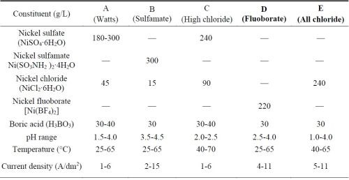
The results with the fluoborate-based solution were presented in our last quarterly report. The CrAlY powder reacted with the fluoborate solution at 50°C and as a result, aluminum hydroxide was generated, leading to the formation of a dark powdery coating. Therefore, the fluoborate bath may be suitable for codeposition of inert particles but not for relatively active metal particles such as the CrAlY-based powders. The current study focused on electroplating of Ni-Co alloy coatings (without CrAlY particles) in the all-chloride solution (E); the coatings plated in the Watts bath (A) were also included for comparison.
III. Experimental procedure
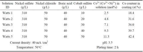
Ni-Co alloy coatings were plated using the all-chloride solution and were compared with the similar coatings plated in the Watts bath. Five all-chloride solutions containing different amounts of cobalt chloride (Table 2) were used to vary the cobalt contents in the Ni-Co alloy coatings. Similarly, the cobalt sulfate concentration was varied in the Watts bath (Table 3). All plating experiments were carried out on Ni 200 disc samples in a glass beaker at a current density of 40 mA/cm2 for 2 hr. The pH values of the all-chloride and Watts solutions were maintained at 2.0 and 3.5, respectively. Electroplating was carried out at room temperature for the all-chloride solution, while the temperature of the Watts bath was set at 50°C.
Table 2 - All-chloride solutions containing different amounts of cobalt chloride and the plating parameters.
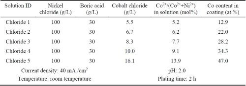
Table 3 - Watts solutions containing different amounts of cobalt sulfate and the plating parameters.
After plating, the specimens were rinsed and ultrasonically cleaned in hot water. The coatings were examined by optical microscopy and scanning electron microscopy (SEM) equipped with energy dispersive spectroscopy (EDS).
IV. Results and discussion
The cobalt contents in the Ni-Co coatings plated from the all-chloride and Watts solutions were determined by EDS. The results are summarized in Tables 2 and 3. The correlation between the cobalt content (at%) in the Ni-Co coating and the Co2+/(Ni2++Co2+) ratio (mol%) in the plating solution is displayed in Fig. 1. The strong dependence of the cobalt content in the coating on the Co2+/(Ni2++Co2+) ratio in the solution was clearly demonstrated, which was in good agreement with the literature data.16-18 Nevertheless, the cobalt content in the Ni-Co coating was consistently higher than that in the plating solution. As an example, for Co2+/(Ni2++Co2+) ranging from 11 to 14% in the solution, the Co/(Ni+Co) in the coating was in the range of 43-47%. The results confirmed the anomalous character of Ni-Co codeposition as previously reported by others, i.e., the less noble metal (cobalt) is preferentially deposited.18-21
A comparison of the results between the all-chloride solution and the Watts bath is also presented in Fig. 1. When the Co2+/(Ni2++Co2+) ratio was lower than ~12%, higher cobalt contents in the Ni-Co coating were obtained from the Watts bath. When the Co2+/(Ni2++Co2+) ratio was greater than that, a higher cobalt level was found in the coatings plated from the all-chloride solution.
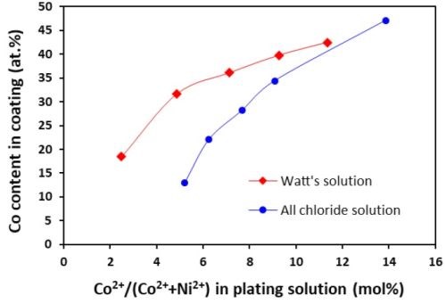
Figure 1 - Relationship between cobalt content in the coating and Co2+/(Ni2++Co2+) ratio in the plating solution.
.jpg;maxWidth=600)
.jpg;maxWidth=600)
.jpg;maxWidth=600)
Figure 2 - Surface morphologies of Ni-Co coatings containing different cobalt contents (in at%) plated in the all-chloride solution (a, c and e) and in the Watts bath (b, d and f). (a-b: 20% Co; c-d: 35% Co; e-f: 45% Co).
The surface morphologies of Ni-Co coatings containing different cobalt contents are shown in Fig. 2. For the Ni-Co coating containing 20% Co, a fine-grained structure was observed for the coating plated in the all-chloride solution (Fig. 2a). Previously, Young and Struyk16 reported that the cobalt-nickel deposit from an all-chloride bath was finer-grained than the one from an all-sulfate bath. As the cobalt content increased, the surface morphology of the Ni-Co coatings changed from smooth to more granular (Figs. 2c and e), as reported by Karpuz, et al.22 For the Ni-Co coatings plated in the Watts bath, polyhedral crystallites were formed for the coatings with lower cobalt content (≤ 20%), Fig. 2b. As the cobalt content increased, globular crystallites were formed whose dimensions appeared to increase with the cobalt content, Figs. 2d and f. It is worth noting that the pH levels of the two solutions were different, which could affect the coating surface morphology too, as previously observed for Co-Mn3O4 composite coatings deposited in the Watts bath.23
References
1. G.W. Goward, Surf. Coat. Technol., 108-109, 73-79 (1998).
2. A. Feuerstein, et al., J. Therm. Spray Technol., 17 (2), 199-213 (2008).
3. C.T.J. Low, R.G.A. Wills and F.C. Walsh, Surf. Coat. Technol., 201 (1-2), 371-383 (2006).
4. F.C. Walsh and C. Ponce de Leon, Trans. Inst. Metal Fin., 92 (2), 83-98 (2014).
5. Y. Zhang, JOM, 67 (11), 2599-2607 (2015).
6. B.L. Bates, J.C. Witman and Y. Zhang, Mater. Manuf. Process, 31 (9), 1232-1237 (2016).
7. J.R. Nicholls, MRS Bull., 28 (9), 659-670 (2003).
8. A.V. Put, D. Oquab and E. Péré, et al., Oxid. Met., 75 (5-6), 247-279 (2011).
9. J.L. Smialek, JOM, 52 (1), 22-25 (2000).
10. B.A. Pint, Oxid. Met., 45 (1-2), 1-37 (1996).
11. G.A. Di Bari, in Modern Electroplating, 5th Ed., Edited by M. Schlesinger and M. Paunovic, John Wiley & Sons, 2010; pp. 79-114.
12. R. Oriňáková, et al., J. Appl. Electrochem., 36 (9), 957-972 (2006).
13. R. Brugger, in Nickel Plating, 1st Ed., Clare O’Molesey Ltd., Molesey, Surrey, 1970; pp. 46-47.
14. H.M. Heiling, Metall., 14, 549-561 (1960).
15. N.V. Parthasaradhy, Practical Electroplating Handbook, Prentice Hall, 1989, p. 184.
16. C.B.F. Young and C. Struyk, Trans. Electrochem. Soc., 89, 383-416 (1946).
17. B. Bakhit, et al., Appl. Surf. Sci., 307, 351-359 (2014).
18. C. Lupi, et al., Surf. Coat. Technol., 205 (23-24), 5394-5399 (2011).
19. C. Fan and D.L. Piron, Electrochim. Acta, 41 (10), 1713-1719 (1996).
20. L. Wang, et al., Appl. Surf. Sci., 242 (3-4), 326-332 (2005).
21. M. Srivastava, et al., Surf. Coat. Technol., 201 (6), 3051-3060 (2006).
22. A. Karpuz, et al., Appl. Surf. Sci., 258 (8), 4005-4010 (2012).
23. S. Apelt, et al., Surf. Coat. Technol., 280, 208-215 (2015).
Past project reports
1. Quarter 1 (January-March 2018): Summary: NASF Report in Products Finishing; NASF Surface Technology White Papers, 82 (12), 13 (September 2018); Full paper: http://short.pfonline.com/NASF18Sep1.
2. Quarter 2 (April-June 2018): Summary: NASF Report in Products Finishing; NASF Surface Technology White Papers, 83 (1), 13 (October 2018); Full paper: http://short.pfonline.com/NASF18Oct1.
3. Quarter 3 (July-September 2018): Summary: NASF Report in Products Finishing; NASF Surface Technology White Papers, 83 (3), 15 (December 2018); Full paper: http://short.pfonline.com/NASF18Dec1.
4. Quarter 4 (October-December 2018): Summary: NASF Report in Products Finishing; NASF Surface Technology White Papers, 83 (7), 11 (April 2019); Full paper: http://short.pfonline.com/NASF19Apr1.
5. Quarter 5 (January-March): Summary: NASF Report in Products Finishing; NASF Surface Technology White Papers, 83 (10), 11 (July 2019); Full paper: http://short.pfonline.com/NASF19Jul1.
6. Quarter 6 (April-June): Summary: NASF Report in Products Finishing; NASF Surface Technology White Papers, 84 (1), 17 (October 2019); Full paper: http://short.pfonline.com/NASF19Oct2.
7. Quarter 7 (July-September): Summary: NASF Report in Products Finishing; NASF Surface Technology White Papers, 84 (3), 16 (December 2019); Full paper: http://short.pfonline.com/NASF19Dec1.
8. Quarter 8 (October-December): Summary: NASF Report in Products Finishing; NASF Surface Technology White Papers, 84 (6), 11 (March 2020); Full paper: http://short.pfonline.com/NASF20Mar3.
9. Quarter 9 (January-March): Summary: NASF Report in Products Finishing; NASF Surface Technology White Papers, 84 (9), 9 (June 2020); Full paper: http://short.pfonline.com/NASF20Jun2.
About the authors

Dr. Ying Zhang is Professor of Mechanical Engineering at Tennessee Technological University, in Cookeville, Tennessee. She holds a B.S. in Physical Metallurgy from Yanshan University (China)(1990), an M.S. in Materials Science and Engineering from Shanghai University (China)(1993) and a Ph.D. in Materials Science and Engineering from the University of Tennessee (Knoxville, Tennessee)(1998). Her research interests are related to high-temperature protective coatings for gas turbine engine applications; materials synthesis via chemical vapor deposition, pack cementation and electrodeposition, and high-temperature oxidation and corrosion. She is the author of numerous papers in materials science and has mentored several Graduate and Post-Graduate scholars.

Mr. Brian L. Bates is a R&D Engineer in the Center for Manufacturing Research at Tennessee Technological University, in Cookeville, Tennessee. He holds B.S. (2002) and M.S. (2010) degrees in Mechanical Engineering from Tennessee Technological University. Mr. Bates also worked at Alcoa-Howmet Corporation (Morristown, Tennessee) and in the Alloy Behavior & Design group at Oak Ridge National Laboratory. Mr. Bates has been actively involved in many research projects on coating fabrication and evaluation.
*Corresponding author:
Dr. Ying Zhang, Professor
Department of Mechanical Engineering
Tennessee Technological University
Cookeville, TN 38505-0001
Tel: (931) 372-3265
Fax: (931) 372-6340
Email: yzhang@tntech.edu
Related Content
Troubleshooting Alkaline Zinc
One of the most common problems that can arise when plating with alkaline zinc is an imbalance of brightener in the solution. In this helpful Ask the Expert article, Chad Murphy of Columbia Chemical discusses how different zinc metal concentrations and brightener concentrations can impact efficiency.
Read MoreProducts Finishing Reveals 2023 Qualifying Top Shops
Each year PF conducts its Top Shops Benchmarking Survey, offering shops a tool to better understand their overall performance in the industry. The program also recognizes shops that meet a set of criteria to qualify as Top Shops.
Read MoreSuccessful South African Plater Beating the Odds
Remaining focused on quality and reliability, Team Plating Works stays profitable in a volatile and challenging economy.
Read MoreAn Overview of Electroless Nickel Plating
By definition, electroless plating is metal deposition by a controlled chemical reaction.
Read MoreRead Next
A ‘Clean’ Agenda Offers Unique Presentations in Chicago
The 2024 Parts Cleaning Conference, co-located with the International Manufacturing Technology Show, includes presentations by several speakers who are new to the conference and topics that have not been covered in past editions of this event.
Read MoreDelivering Increased Benefits to Greenhouse Films
Baystar's Borstar technology is helping customers deliver better, more reliable production methods to greenhouse agriculture.
Read MoreEducation Bringing Cleaning to Machining
Debuting new speakers and cleaning technology content during this half-day workshop co-located with IMTS 2024.
Read More


