Electro-codeposition of MCrAlY Coatings for Advanced Gas Turbine Applications - Complete Project Report
This is the complete final project report of the three-year AESF Foundation Research project (2018-2020) at the Tennessee Technological University, Cookeville, TN., to optimize the electro-codeposition process for improved oxidation/corrosion performance of MCrAlY coatings on critical superalloy components in gas turbine engines.
by
Prof. Ying Zhang*
Department of Mechanical Engineering
Tennessee Technological University
Cookeville, Tennessee, USA
Editor’s Note: This is the complete final project report of the three-year AESF Foundation Research project (2018-2020) at the Tennessee Technological University, Cookeville, Tennessee. A printable PDF version of this report is available by clicking HERE.
SUMMARY
Electrolytic codeposition is a promising alternative low-cost process for fabricating MCrAlY coatings. In this process, CrAlY particles are codeposited with the (Ni,Co) to form an (Ni,Co)-CrAlY composite coating, which is subsequently heat treated at elevated temperatures to be transformed to the MCrAlY coating containing phases of β-NiAl, γ-(Ni,Co), etc. Two types of CrAlY-based particles (made by ball milling and gas atomization) were employed. The effects of several key processing parameters, such as current density, particle loading, and particle size/shape density, on the CrAlY particle incorporation in the electrodeposited (Ni,Co)-CrAlY coatings were studied. For the ball-milled CrAlY powder, an increase in current density led to a decrease in particle incorporation, whereas for the gas-atomized CrAlY powder the current density showed a negligible influence on particle incorporation. The relationship of particle incorporation and particle loading followed the Langmuir adsorption isotherm. One of the most important findings was that the particle properties played a critical role in affecting particle incorporation. For CrAlY particles of similar size, the spherical-shaped particles led to higher incorporation than the irregular particles. This was likely because fewer electrolyte ions were adsorbed on the particles with smaller specific surface areas, leading to the higher specimen-particle adsorption strength. In addition, sulfur-free plating solutions were explored in the electro-codeposition process, since the MCrAlY coatings plated in a Watts bath typically contain a trace amount of sulfur, which could adversely affect the high-temperature oxidation resistance. Preliminary oxidation testing was conducted at 1100°C to evaluate the oxidation performance of the coatings plated in the sulfur-free solutions.
I. Introduction
To improve high-temperature oxidation and corrosion resistance of critical superalloy components in gas turbine engines, metallic coatings such as diffusion aluminides or MCrAlY overlays (where M = Ni, Co or Ni+Co) have been employed, which form a protective oxide scale during service.1 The state-of-the-art techniques for depositing MCrAlY coatings include electron beam-physical vapor deposition (EB-PVD) and thermal spray processes.1 Despite the flexibility they permit, these techniques remain line-of-sight, which can be a real drawback for depositing coatings on complex-shaped components. Further, high costs are involved with the EB-PVD process.2 Several alternative methods of making MCrAlY coatings have been reported in the literature, among which electro-codeposition appears to be a more promising coating process.
Electrolytic codeposition (also called “composite electroplating”) is a process in which fine powders dispersed in an electroplating solution are codeposited with the metal onto the cathode (specimen) to form a multiphase composite coating.3,4 The process for fabrication of MCrAlY coatings involves two steps. In the first step, pre-alloyed particles containing elements such as chromium, aluminum and yttrium are codeposited with the metal matrix of Ni, Co or (Ni,Co) to form a (Ni,Co)-CrAlY composite coating. In the second step, a diffusion heat treatment is applied to convert the composite coating to the desired MCrAlY coating microstructure with multiple phases of β-NiAl, γ-Ni, etc.5
Compared to conventional electroplating, electro-codeposition is a more complicated process because of the particle involvement in metal deposition. It is generally believed that five consecutive steps are engaged:3,4 (i) formation of charged particles due to ions and surfactants adsorbed on particle surface, (ii) physical transport of particles through a convection layer, (iii) diffusion through a hydrodynamic boundary layer, (iv) migration through an electrical double layer and finally, (v) adsorption at the cathode where the particles are entrapped within the metal deposit. The quality of the electro-codeposited coatings depends upon many interrelated parameters, including the type of electrolyte, current density, pH, concentration of particles in the plating solution (particle loading), particle characteristics (composition, surface charge, shape, size), hydrodynamics inside the electroplating cell, cathode (specimen) position, and post-deposition heat treatment if necessary.3-6
There are several factors that can significantly affect the oxidation and corrosion performance of the electrodeposited MCrAlY coatings, including: (i) the volume percentage of the CrAlY powder in the as-deposited composite coating, (ii) the CrAlY particle size/distribution and (iii) the sulfur level introduced into the coating from the electroplating solution. This three-year project aimed to optimize the electro-codeposition process for improved oxidation/corrosion performance of the MCrAlY coatings. The three main tasks were as follows:
- Task 1 (Year 1): Effects of current density and particle loading on CrAlY particle incorporation.
- Task 2 (Year 2): Effect of CrAlY particle size on CrAlY particle incorporation.
- Task 3 (Year 3): Effect of electroplating solution on the coating sulfur level.
II. Background
A typical MCrAlY coating consists of 8–12% Al, 18–22% Cr and up to 0.5% Y (wt%). Other more complicated compositions of MCrAlYs contain additional elements such as hafnium, silicon and tantalum.7,8 The concentrations of some minor elements (e.g., sulfur, yttrium and hafnium) play an important role in affecting the growth and adhesion of the oxide scale. The detrimental effect of sulfur on oxide scale adherence of MCrAlY alloys has been well documented.9 Small amounts of sulfur can segregate to the alumina-metal interface and weaken the interface.10 An earlier study by Bornstein, et al.11 clearly showed the effect of concentrations of sulfur and yttrium on the cyclic oxidation resistance of NiCrAlY alloys at 1100°C. For NiCrAlY alloys containing 40 ppm S, an addition of 890 ppm Y could effectively mitigate the sulfur effect and an adherent oxide scale was maintained. However, for NiCrAlYs containing 300 ppm S, 4000 ppm of Y was not able to counteract the sulfur effect.
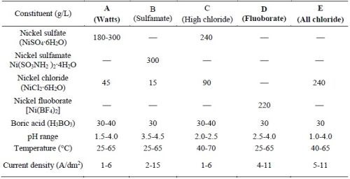
The electrolytes used to deposit the nickel or cobalt metal matrix for forming the MCrAlY coating are typically sulfate- or sulfamate-based solutions.12,13 Approximately 0.006-0.013 wt% (60-130 ppm) of sulfur has been reported in electroplated nickel coatings using these solutions.14,15 Table 1 lists the five commercial nickel plating solutions and their deposition parameters.16 The Watts bath (Solution A) is the most commonly used electrolyte. The large amount of nickel sulfate provides the necessary concentration of nickel ions. Nickel chloride improves anode corrosion and also increases conductivity. Boric acid is added as a weak buffer to maintain pH. As shown in Table 1, there are three sulfur-free plating solutions (C, D and E). The proposed work has been focused on Solutions D and E; Solution C (high chloride) was not selected due to the very narrow pH range (2.0-2.5) required.
Table 1 - Composition of Ni plating solutions and deposition conditions (adapted from Ref. 16).
III. Experimental procedure
3.1. Sample preparation
Substrates were made from available nickel-based alloys including Ni 200 (>99.0Ni, with 0.25Cu-0.40Fe-0.35Mn-0.15C-0.35Si-0.01S max.), René 80 (Ni-3.0Al-14.1Cr-9.7Co-4.3W-4.0Mo-5.0Ti-0.18C (in wt%), 130B-200Zr-7S (in ppmw), and CMSX-4 (Ni-5.9Al-6.3Cr-9.6Co-6.5W-0.6Mo-2.9Re-6.5Ta-1.0Ti (in wt%), 1100Hf-17C-1S (in ppmw). Disc specimens (1.6 mm thick, ~17 mm in diameter) were cut using an abrasive cutting saw. The specimens were ground to #600 grit using SiC grinding paper, followed by grit-blasting with #220 Al2O3 grit and ultrasonic cleaning in hot water and acetone.
3.2. Powder preparation and particle analysis
A variety of powders were prepared including gas-atomized CrAlY and CoNiCrAlY powders, as well as ball-milled CrAlY-based powders (Table 2). The atomized CrAlY and CoNiCrAlY powders were purchased from Sandvik Materials Technology and Phoenix Scientific Industries Ltd, respectively. The ball-milled powders were made at Tennessee Technological University (TTU). For TTU powders, a cast ingot was made via arc melting, which was crushed with a hammer and then ball-milled in a high-energy ball mill for 30-45 min. Both atomized and ball-milled powders were sieved through a 20-m screen (625 mesh).
Table 2 - Chemical compositions of alloy powders used in the electro-codeposition experiments.

To further control the particle size distribution of the ball-milled powder, a water elutriation method17 was used to separate the particles smaller than 5 μm and larger than 20 μm from the original powder. This method utilizes the relationship between the particle size and terminal velocity to sort out particles of different sizes.
Particle analysis was carried out using a Malvern Mastersizer 2000 Laser diffractor. The density of the alloy powder was determined using a pycnometer (AccuPyc 1340).
3.3. Electro-codeposition
A rotating barrel system shown in Fig. 1 was used in the electro-codeposition experiments. The 185-mL barrel was constructed of a rigid polypropylene frame covered by a thin nylon membrane with ~1 μm mesh size. The nylon membrane allows the exchange of plating solution between the barrel and the tank, but prohibits escaping of the particles. The barrel was attached to a gear set driven by a variable speed DC motor. The barrel and gear set were then suspended in a 5-L tank of Watts nickel plating solution such that the barrel was fully submerged. Specimens were placed longitudinally inside the barrel and centered on the barrel’s axis of rotation. To connect the specimen to the power supply, a flexible metal wire covered with Teflon tubing was attached to the sample. A solid nickel anode was placed outside of the barrel along with a mechanical stirrer and heating coil. The specimens were plated at a current density of 20 mA/cm2 for 2 hr at 50°C with the pH of about 3.5. The particle concentration in the bath was kept at 20 g/L and the barrel rotation speed at 7 RPM.
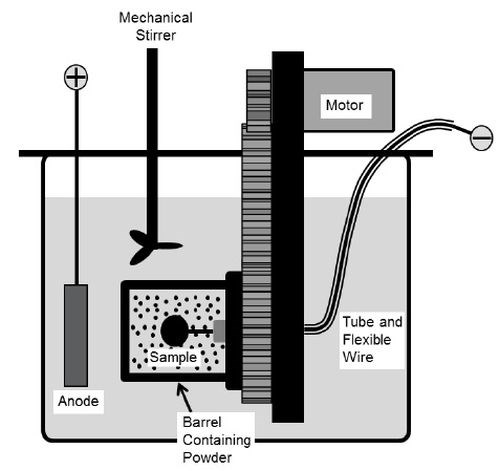
Figure 1 – Schematic of the barrel system.
Ni-Co alloy coatings were also plated using the Watts bath containing different amounts of cobalt sulfate (Table 3). The resultant coatings were compared to the Ni-Co coatings plated in the all-chloride solution containing different amounts of cobalt chloride (Table 4). These experiments were carried out in a glass beaker at a current density of 40 mA/cm2. The pH values of the Watts and all-chloride solutions were maintained at 3.5 and 2.0, respectively. In contrast to the Watts bath, electroplating was conducted at room temperature in the all-chloride solution.
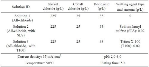
To seek a suitable sulfur-free bath, investigation was focused on the fluoborate and the all-chloride solutions. In addition, the all-chloride solution (Table 5) with different types of wetting agent were prepared. The sulfur-containing wetting agent was sodium lauryl sulfate (SLS), and the sulfur-free one was Triton X-100 (T100).18
Table 3 - Watts solutions containing different amounts of cobalt sulfate and the plating parameters.
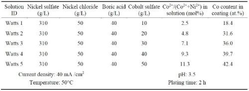
Table 4 - All chloride solutions containing different amounts of cobalt chloride and the plating parameters.
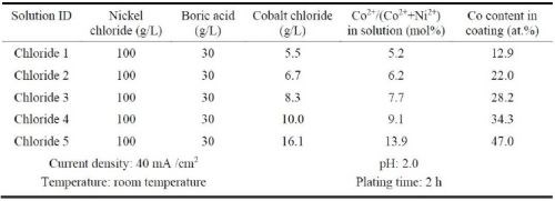
Table 5 - Composition of all-chloride solutions and plating conditions
3.4. Coating characterization
The as-deposited coatings were examined using scanning electron microscopy (SEM). Prior to metallographic sample preparation, the specimens were copper-plated. To determine the quantity of particles incorporated in the coating, multiple backscattered-electron images were taken at different locations along the coating cross-section, which were then processed using ImageJ software.
3.5. Post-plating heat treatment and oxidation testing
After plating, selected specimens were heat-treated in vacuum for 6 hr at 1080°C. The purpose of the heat treatment was to convert the as-deposited Ni/Co-CrAlY composite coating to the NiCoCrAlY coatings that consisted of phases such as γ-(Ni,Co), β-NiAl, etc. The post-deposition heat treatment was carried out in a horizontal alumina tube furnace. A vacuum of at least 10-6 torr was maintained. The heating rate was 20°C/min. After completion, the samples were furnace cooled to room temperature.
The oxidation performance of the MCrAlY coatings was evaluated in cyclic oxidation testing at Oak Ridge National Laboratory (ORNL). The test was carried out in laboratory air with 1-hr cycles at 1100°C with a 10-minute cooling period. The specimens were removed and weighed every 20 cycles for the first 100 hours and every 50 cycles thereafter. The mass changes (±0.02 mg/cm2 accuracy) were recorded.
IV. Results and discussion
4.1. Powder characteristics and as-deposited coatings
Figure 2 shows the particle analysis results for ball-milled CrAlY (TTU), atomized CoNiCrAlY (PSI), and atomized CrAlY (Sandvik) powders. The ball-milled CrAlYTa (TTU) powder had a particle size distribution similar to that of the ball-milled CrAlY (TTU) powder due to the same powder preparation procedure, which was not measured. Powder characteristics, including particle size, shape and density, are summarized in Table 6.
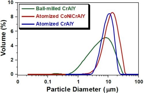
Figure 2 - Particle size distribution differential plots of ball-milled and atomized powders.
Table 6 - Powder characteristics.

Values of D10, D50 and D90 describe that 10%, 50% and 90% of the particles (based on volume) have a particle size smaller than the value given. TTU ball-milled powder had a D50 value smaller than those of commercial atomized powders (5.6 vs. 10-12 μm). The density of CrAlYTa powder (5.5 g/cm3) was slightly higher than the baseline CrAlY powder (4.5 g/cm3) due to the tantalum addition, and the CoNiCrAlY had an even higher density (7.8 g/cm3) with additional cobalt and nickel. The ball-milled powder also exhibits an irregular shape, in contrast to the spherical shape of the gas-atomized powder. It is worth pointing out that the CoNiCrAlY powder (with cobalt and nickel) does not have the desired chemical composition for making the MCrAlY coatings; it was included in the experiments in order to understand the effect of powder density on the particle incorporation in the electro-codeposited coatings.
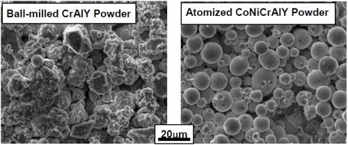
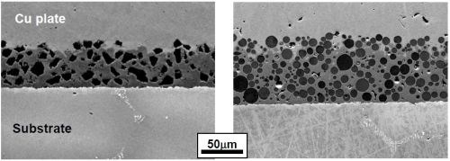
Figures 3 and 4 display the representative microstructures of the electro-codeposited coatings using two different powders (ball-milled CrAlY and atomized CoNiCrAlY). The different shapes of the particles can be clearly seen from both the surface and cross-section of the as-coated specimens. The atomized particles were mostly spherical, while the ball-milled CrAlY powders were asymmetric. Further observation of the surface showed growth of the nickel deposit on the particles, in addition to the nickel matrix, as these particles are conductive. It appears that the geometries of the particles could also lead to the different surface roughness observed on the coated specimens. Additionally, based on the image analysis results, the particle incorporation for CoNiCrAlY powder was significantly greater than the CrAlY powder, 46 vs. 30 vol%. The effect of particle shape on particle incorporation will be discussed in Section 4.5.
(a) (b)
Figure 3 - SEM surface images of the coatings with (a) ball-milled CrAlY and (b) atomized milled CrAlY powders.
(a) (b)
Figure 4 - SEM cross-sectional images of the coatings with (a) ball-milled CrAlY and (b) atomized CoNiCrAlY powders.
4.2. Effect of current density on particle incorporation
To form a typical NiCrAlY coating contain 8-12% Al, 18-22% Cr and 0.5% Y (in wt%), about 40 vol% of CrAlY particles would be needed in the as-deposited composite coatings, based on the chemical composition and the density of the CrAlY powder used in this study.5 In addition to achieving a uniform and adherent coating, incorporation of a high percentage of CrAlY particles in the nickel matrix is another important requirement for the electro-codeposition process.
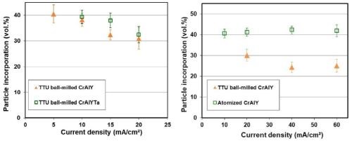
The effect of current density on CrAlY(Ta) particle incorporation is displayed in Fig. 5. For ball-milled CrAlY and CrAlYTa powders, the particle incorporation in the as-deposited coatings decreased from ~40 to 30-33 vol% as the current density was increased from 5 to 20 mA/cm2 (Fig. 5a). The particle incorporation continued to drop to 25 vol% when the current density was further increased to 40 mA/cm2 and remained at ~25 vol% for current densities between 40 and 60 mA/cm2 (Fig. 5b). For gas-atomized CrAlY powder, the current density appeared to have little influence on the particle incorporation, while an overall higher particle volume percentage (40-43 vol%) was observed for the entire current density range (10-60 mA/cm2) employed in this study.
(a) (b)
Figure 5 - Particle incorporation in the coating as a function of plating current density: (a) in the low current density range with ball-milled CrAlY and CrAlYTa powders, and (b) in the high current density range with ball-milled and atomized CrAlY powders.
Current density is a critical process parameter in conventional electroplating that governs the deposition rate. However, the effect of current density on particle incorporation depends strongly on the nature of particles and the metal deposit. Different types of relationships have been observed,19 i.e., the particle content in the composite coatings either increases or decreases continuously with the current density or exhibits one or multiple peaks as a function of current density. The present findings for gas-atomized CrAlY powder are in good agreement with an earlier study conducted by Foster, et al.20 for coatings plated under several conditions using CrAlY particles in a rotating barrel configuration. Similar results were also observed by Liu and Chen for Ni-Al composite coatings made with sediment codeposition,21 in which the current density showed minimal influence on the aluminum particle incorporation between 20 and 90 mA/cm2. The current density dependence for conducting particles is generally different than non-conducting particle systems such as Ni-Al2O3 and Ni-SiC, as reported in the literature.22,23
Current density also has an effect on the overall coating quality by affecting the porosity and thickness uniformity. Higher current densities typically result in preferential deposition at the edges and corners of the specimen, which can cause higher stresses and consequently coating cracking/spallation in those areas. On the other hand, at lower current densities, if the rate of metal deposition cannot keep up with the speed of particle settlement, there is a tendency to form less dense coatings with noticeable voids.
4.3. Effect of particle loading on particle incorporation
Figure 6 shows the particle incorporation in these metal matrix composite coatings as a function of the particle loading. For the MCrAlY powder, when the particle concentration in the plating solution was increased from 10 to 30 g/L, the particle incorporation remained around 50 vol%. For the CrAlYTa powder, an increase of the particle incorporation was observed for 20 mA/cm2 as the particle loading was increased from 20 to 40 g/L, while a further increase of particle loading from 40 to 60 g/L did not lead to a drastic increase in particle incorporation. At the lower current density levels (e.g., 10-15 mA/cm2), the effect of particle loading was not evident for the CrAlYTa powder.
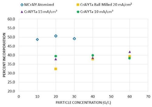
Figure 6 - Effect of particle concentration on particle incorporation in the as-deposited coatings for commercial atomized MCrAlY and laboratory ball-milled CrAlYTa powders.
Particle loading is one of the important factors affecting the particle incorporation in electro-codeposited composite coatings. Several studies have shown that when the particle concentration in the plating solution is low, increases in particle concentration lead to substantial increases in particle incorporation in the coating.20,21,24-26 However, as the particle loading increases, the increase in particle incorporation begins to plateau. Such a tendency is consistent with the Langmuir adsorption isotherm on the electrode surface.27 For plating solutions with a low particle concentration, the particle incorporation is limited by the supply of particles to the cathode (i.e., the specimen) surface by agitation and diffusion. Increasing the overall amount of particles in the solution enhances the probability of particles of reaching the electrochemical double layer at the cathode and thus improves particle incorporation. However, hydrodynamic effects due to particle-particle interactions become more dominant at high particle concentrations, and thus have a negative impact on particle incorporation.
Although this trend has been confirmed for a wide range of metal particle systems, the threshold particle concentration at which saturation (the plateau) occurs depends on the powder characteristics and the electro-codeposition conditions.28 Susan25 studied Ni-Al composite coatings containing aluminum particles (1.5-3.5 μm size) embedded in a nickel matrix electrodeposited in a vertical arrangement in a beaker, and observed a plateau at 300-400 g/L. In a later study carried out by Liu26 using a horizontal sedimentation configuration, the plateau occurred at ~40 g/L. In our current study, for gas-atomized MCrAlY particles with a higher density (7.5 g/cm3) and larger particle size (12.5 μm), the plateau started at a lower particle concentration (10 g/L) with a plating current density of 20 mA/cm2. For ball-milled CrAlYTa powder with a reduced density (5.5 g/cm3) and particle size (5.6 μm), the plateau was observed at ≥40 g/L at 20 mA/cm2, whereas the plateau started at 20 g/L with 10-15 mA/cm2 current densities. The overall trend, however, was in good agreement with previous findings in the literature.
4.4. Effect of particle size on particle incorporation
Figure 7 shows the SEM cross-sectional images of the NiCo-CrAlY coatings deposited using powders with different particle sizes. The coating displayed in Figs. 7(a & c) was plated using the 5-μm CrAlY powder and the coating with the 10-μm powder is shown in Figs. 7(b & d). The difference in particle size can be clearly seen, particularly at the higher magnification, Figs. 7(c &d). It is worth noting that while all other electro-codeposition parameters remained the same, the plating time was different for the two coating samples, resulting in different coating thicknesses.
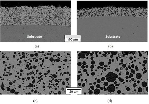
Figure 7 - SEM cross-sectional images of as-deposited NiCo-CrAlY coatings plated using powders with different particle sizes: (a) and (c) 5-μm particles; (b) and (d) 10-μm particles.
Table 7 summarizes the CrAlY particle incorporation in the coatings deposited with 5- and 10-μm powders with different particle concentrations in the plating solution. When the CrAlY particle loading was increased from 20 to 60 g/L, the particle incorporation in the NiCo-CrAlY coating was increased, especially for the 5-μm powder. Regardless of the particle loading, consistently higher particle incorporation (based on vol%) was obtained for the 10-μm powder, ~36%, as compared to the 5-μm powder (28-31%).
Table 7 - Summary of CrAlY particle incorporation in NiCo-CrAlY coatings.

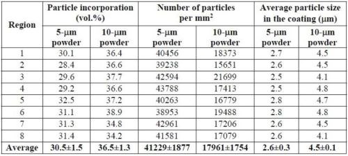
Table 8 provides a more detailed comparison between the volume fraction of particle incorporation and the number of particles in the coatings plated with 60 g/L particle loading. The measurements were taken in eight different areas on each specimen. Although the coating deposited using the 10-μm powder showed higher volume fractions of CrAlY particles, the number of particles per unit area was much lower, approximately 44% of what was incorporated in the coating deposited with the 5-μm powder. In addition, for both powders, the average size of the embedded particles was much smaller (about half) than that of the starting powders.
Table 8 - Comparison of the volume fraction and the number of CrAlY particles in the coating for 60 g/L particle loading.
Particle size and density can change the magnitude of forces acting on the particles both while being suspended in the solution and when in contact with the component surface. When a sedimentation or barrel configuration is used, the velocity of the particle is dictated by a balance of gravitational forces and hydrodynamic drag forces. For larger and heavier particles, the agitation required to suspend the particles becomes quite high. In addition, larger particles are more susceptible to hydrodynamic forces further diminishing their ability to be embedded. Both particle size and density have been shown to increase the sediment velocity of the particles.20,29 The increase of particle velocity can increase the particle transport to the component surface, which in turn increases the particle concentration at the surface. Nevertheless, not only is gravity acting on the particles, but electrophoretic, hydrodynamic and electrochemical forces are also exerting on the particles. Additionally, adhesion forces are being applied to the particles as the metal matrix forms around the particle. The sum of these forces dictates if a particle will become permanently incorporated in the coating.
4.5. Effect of particle shape and density on particle incorporation
Very limited data were available with regard to the influence of particle geometry on particle incorporation, probably due to the restricted availability of commercial powders that have the same composition and particle size, but different particle shapes. In this study, water elutriation made it possible to select the particles with D50 = 11 μm from the ball-milled CrAlY powder to match the particle size of the atomized CrAlY powder with D50 = 10 μm. The spherical particles had a slightly higher density (5.0 g/cm3) than the irregular particles (4.5 g/cm3).
Figure 8 shows the SEM cross-sectional images of the Ni-CrAlY coatings that were deposited using the two types of powders. Similar to Fig. 4, the difference in the CrAlY particle shape can be clearly seen. The CrAlY particle incorporation as a function of current density is presented in Fig. 9. Under the same codeposition conditions, the CrAlY particle incorporation was ≤ 30 vol% when the irregularly-shaped powder was used, while greater than 42 vol% of particle incorporation was obtained for the spherical gas-atomized powder.
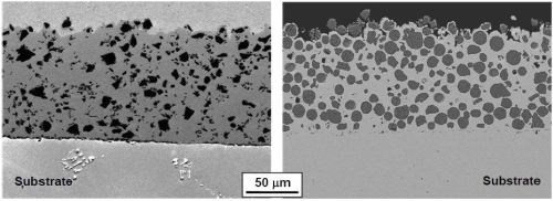
Figure 8 - Cross sections of Ni-CrAlY coatings deposited using (a) ball-milled and (b) gas-atomized powders.
The gas-atomized CrAlY powder had a slightly higher density (5.0 g/cm3) than the ball-milled powder (4.5 g/cm3). In order to confirm that the increase in particle incorporation was mainly due to the particle shape rather than the density, ball-milled CrAlY and CrAlYTa powders with different densities were employed in the electro-codeposition. As shown in Fig. 10, only very small increases of particle incorporation were observed for the CrAlYTa particles with a higher density. Hence, most of the changes in particle incorporation were due to the difference in particle shape between the spherical gas-atomized powder and the irregular ball-milled powder.
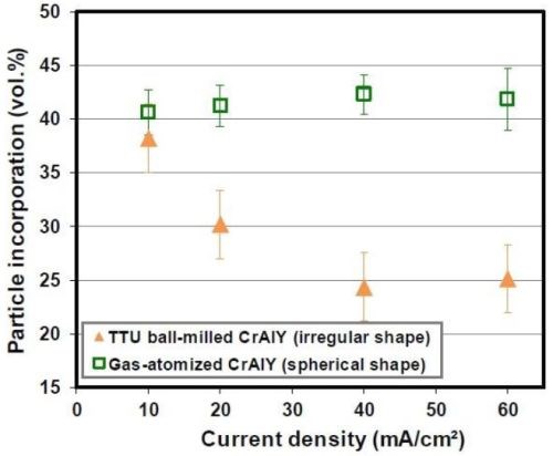
Figure 9 - Effect of the CrAlY particle shape on particle incorporation.
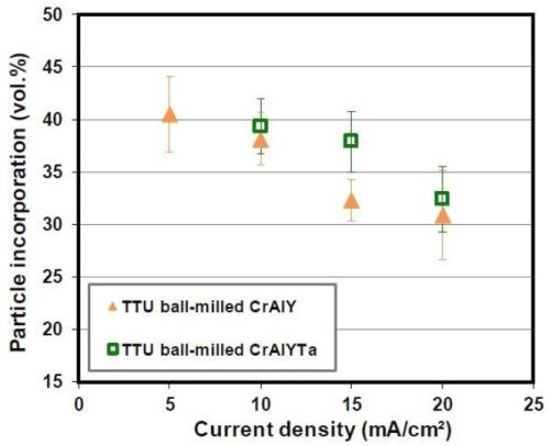
Figure 10 - Effect of CrAlY(Ta) particle density on particle incorporation.
So far, most studies related to the effects of particles was focused on chemical composition, size and conductivity of the particles.29-32 In contrast, the effects of particle size shape and density have not received much attention. The results of the present study suggest that the shape of the particles plays an important role in the electro-codeposition process. These results are also consistent with the findings by Apachitei,33 where the spherical Al2O3 particles were found to lead to an increase in particle incorporation compared to the irregular Al2O3 particles in the NiP-Al2O3 coatings (i.e., 33 vs. 28 vol%). The author attributed the increase in particle incorporation to decreases in the specific surface area of the particles. A possible theory is that spherical particles with lower specific surface areas require fewer metal ions to be deposited for a given volume, resulting in an increase of the volume of particles relative to the volume of deposited metal.
4.6. Sulfur-free solution and preliminary oxidation testing
Electro-codeposition experiments were also conducted in the fluoborate bath with the addition of CrAlY powder. However, when the powder was added, the fluoborate solution violently reacted with the powder. After the powder was thoroughly mixed with the solution, a significant drop of pH from 3.4 to ~2.0 was observed. Nickel carbonate was used to increase the pH of the plating solution to 2.5. Further solution pH modification was found to be difficult by adding more nickel carbonate. Since such a pH value was still in the recommended range for the fluoborate bath, the electro-codeposition was carried out at pH of 2.5. When the current was applied, small gas bubbles were noticed on both the cathode (specimen) and the anodes. Even with vigorous agitation, a uniform suspension could not form. Instead, several distinct layers were observed in the beaker. The specimen plated in the fluoborate solution exhibited a dark powdery surface. Based on the EDS analysis, in addition to the expected elements of Ni, Cr and Al, other elements such as F and O were also detected on the coating surface. These impurities were introduced to the coating during electro-codeposition.
Although the fluoborate solution is sulfur-free and offers high plating rates, the fluoborate anion is aggressive. Some metallic materials that contact the solution can be chemically attacked, among which are aluminum, lead, titanium, and high silicon cast iron.12,34 In the electro-codeposition process, the CrAlY powder reacted with the fluoborate solution at 50°C and formed aluminum hydroxide, leading to the presence of the high oxygen peak on the specimen surface. Therefore, the fluoborate-based plating bath may be suitable for codeposition of more inert particles but not for relatively active metal particles such as the CrAlY-based powders. Subsequent work was focused on the other sulfur-free bath, i.e., the all-chloride solution.
The cobalt contents in the Ni-Co coatings plated from the Watts and all-chloride solutions were determined by EDS. The results are also included in Tables 3 and 4. The correlation between the cobalt content (at%) in the Ni-Co coating and the Co2+/(Ni2++Co2+) ratio (mol%) in the plating solution is displayed in Fig. 11. The strong dependence of the cobalt content in the coating on the Co2+/(Ni2++Co2+) ratio in the solution was clearly demonstrated, which was in good agreement with the literature data.35-37 Nevertheless, the cobalt content in the Ni-Co coating was consistently higher than that in the plating solution. As an example, for Co2+/(Ni2++Co2+) ranging from 11 to 14% in the solution, the Co/(Ni+Co) in the coating was in the range of 43-47%. The results confirmed the anomalous character of Ni-Co codeposition as previously reported by others, i.e., the less noble metal (cobalt) is preferentially deposited.37-40
A comparison of the results between the all-chloride solution and the Watts bath is also presented in Fig. 11. When the Co2+/(Ni2++Co2+) ratio was lower than ~12%, higher cobalt contents in the Ni-Co coating were obtained from the Watts bath. When the Co2+/(Ni2++Co2+) ratio was greater than that, a higher cobalt level was found in the coatings plated from the all-chloride solution.
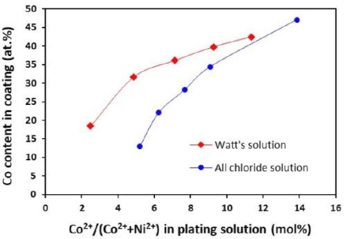
Figure 11 - Relationship between cobalt content in the coating and Co2+/(Ni2++Co2+) ratio in the plating solution.
The surface morphologies of Ni-Co coatings containing different cobalt contents are shown in Fig. 12. For the Ni-Co coating containing 20% Co, a fine-grained structure was observed for the coating plated in the all-chloride solution (Fig. 12a). Previously, Young and Struyk35 reported that the cobalt-nickel deposit from an all-chloride bath was finer-grained than the one from an all-sulfate bath. As the cobalt content increased, the surface morphology of the Ni-Co coatings changed from smooth to more granular (Figs. 12c and e), as reported by Karpuz, et al.41 For the Ni-Co coatings plated in the Watts bath, polyhedral crystallites were formed for the coatings with lower cobalt content (≤ 20%), Fig. 12b. As the cobalt content increased, globular crystallites were formed whose dimensions appeared to increase with the cobalt content, Figs. 12d and f. It is worth noting that the pH levels of the two solutions were different, which could affect the coating surface morphology too, as previously observed for Co-Mn3O4 composite coatings deposited in the Watts bath.42
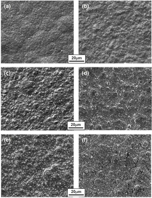
Figure 12 - Surface morphologies of Ni-Co coatings containing different cobalt contents (in at%) plated in the all-chloride solution (a, c and e) and in the Watts bath (b, d and f); (a-b: 20% Co; c-d: 35% Co; e-f: 45% Co).
The coatings plated in the all-chloride solutions containing different SLS and T 100 wetting agent were also compared. Figure 13 shows the coating surface morphologies before and after heat treatment. The surface compositions determined by EDS are summarized in Table 9. For all three coatings, a decrease in Cr content was observed, as a result of Cr evaporation in vacuum at 1080°C, similar to what was reported for MCrAlY coatings made by thermal spraying and EB-PVD.43,44
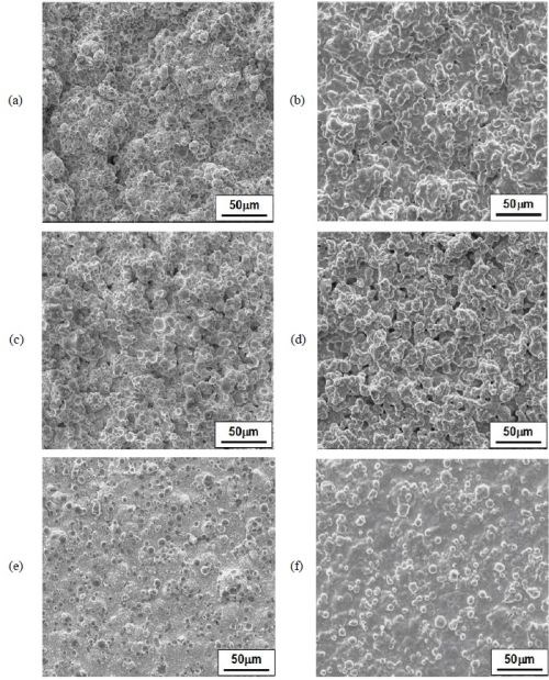
Figure 13 - SEM surface images of the specimens for oxidation tests before and after heat treatment:
- (a) and (b): sample plated in the all-chloride solution (Coating #1, without wetting agent);
- (c) and (d): sample plated in the all-chloride solution with SLS wetting agent (Coating #2);
- (e) and (f): sample plated in the all-chloride solution with TX100 wetting agent (Coating #3).
Table 9 - Coating surface compositions before and after heat treatment, as determined by EDS (wt%).
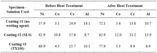
Coating #2 (plated in the solution with SLS) had higher Co, Cr and Al levels. Coating #1 (plated in the solution without wetting agent) had acceptable levels of Cr and Al, whereas the Co content was the lowest (i.e., 3.4 wt%). This was possibly due to a lower cathode efficiency, since there was no wetting agent in this solution and the specimen was plated at a lower pH value. The Co, Cr and Al levels were lower for Coating #3 (plated in the solution with T100). This was likely due to a lower particle incorporation in the coating.
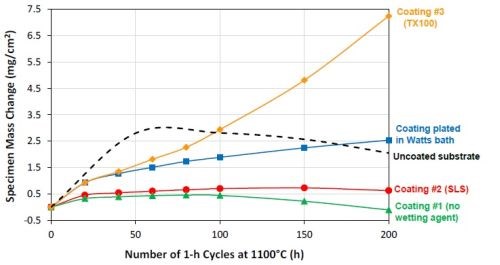
Figure 14 – Specimen mass changes during 1-hr cyclic oxidation in laboratory air at 1100°C.
Figure 14 shows the specific mass changes after cyclic oxidation testing at 1100°C (200, 1-hr cycles). The uncoated CMSX-4 substrate and a previous coating plated in the Watts bath were also included for comparison. A coating with good oxidation resistance should have a slow and steady growth in weight, due to the formation of a thin and adherent Al2O3 scale on the surface. Coating #1 had a slow steady mass gain in the first 100 cycles, but started to lose weight after 100 hr, indicating spallation of the oxide scale. Coating #3 (T100), on the other hand, showed a very rapid mass gain, as a result of fast growth of the oxide scale. Coating #2 (SLS) had the best oxidation performance, exhibiting a steady mass gain and only started to show signs of mass loss near the end of the 200-hr test. This coating also demonstrated much better oxidation resistance than the bare CMSX-4 alloy and exhibited lower weight gain than the coating plated in the Watts bath. In addition, the oxidation results were in good agreement with the coating surface composition.
The current oxidation results suggest that with the proper wetting agent, the all-chloride solution can be used to reduce the sulfur content in the MCrAlY coatings and satisfactory oxidation performance could be achieved. Further evaluation is needed to elucidate the effects of wetting agent on both coating quality and oxidation behavior.
Acknowledgements
This research was sponsored by the AESF Foundation, Research Project #R-119 (Dr. E. Jennings Taylor, Technical Monitor). The author would also like to thank Dr. James Lindsay (NASF Technical Editor) for providing helpful comments on all quarterly reports.
References
1. G.W. Goward, Surf. Coat. Technol., 108-109, 73-79 (1998).
2. A. Feuerstein, et al., J. Therm. Spray Technol., 17 (2), 199-213 (2008).
3. C.T.J. Low, R.G.A. Wills and F.C. Walsh, Surf. Coat. Technol., 201 (1-2), 371-383 (2006).
4. F.C. Walsh and C. Ponce de Leon, Trans. Inst. Metal Fin., 92 (2), 83-98 (2014).
5. Y. Zhang, JOM, 67 (11), 2599-2607 (2015).
6. B.L. Bates, J.C. Witman and Y. Zhang, Mater. Manuf. Process, 31 (9), 1232-1237 (2016).
7. J.R. Nicholls, MRS Bull., 28 (9), 659-670 (2003).
8. A.V. Put, D. Oquab and E. Péré, et al., Oxid. Met., 75 (5-6), 247-279 (2011).
9. J.L. Smialek, JOM, 52 (1), 22-25 (2000).
10. B.A. Pint, Oxid. Met., 45 (1-2), 1-37 (1996).
11. N.S. Bornstein, M.A. DeCrescente and J.G. Smeggil, Mater. Sci. Eng., A120, 175-178 (1989).
12. G.A. Di Bari, in Modern Electroplating, 5th Ed., Edited by M. Schlesinger and M. Paunovic, John Wiley & Sons, 2010; pp. 79-114.
13. R. Oriňáková, et al., J. Appl. Electrochem., 36 (9), 957-972 (2006).
14. R. Brugger, in Nickel Plating, 1st Ed., Clare O’Molesey Ltd., Molesey, Surrey, 1970; pp. 46-47.
15. H.M. Heiling, Metall., 14, 549-561 (1960).
16. N.V. Parthasaradhy, Practical Electroplating Handbook, Prentice Hall, 1989, p. 184.
17. L.R. Follmer and A.H. Beavers, J. Sedimentary Res. (formerly J. Sedimentary Petrology), 43 (2), 544-549 (1973).
18. S. Devaraj and N. Munichandraiah, J. Electrochem. Soc., 154 (10), A901-A909 (2007).
19. A. Hovestad, R.J.C.H.L. Heesen and L.J.J. Janssen, J. Appl. Electrochem., 29 (3), 331-338 (1999).
20. J. Foster, et al., Trans. Inst. Met. Finish., 63 (1), 115-119 (1985).
21. H. Liu and W. Chen, Surf. Coat. Technol., 191 (2-3), 341-350 (2005).
22. K. Barmak, et al., J. Microsc., 185 (2), 265-274 (1997).
23. S.C. Wang and W.C.J. Wei, Mater. Chem. Phys., 78 (3), 574-580 (2003).
24. R. Narayan and B.H. Narayana, J. Electrochem. Soc., 128 (8), 1704-1708 (1981).
25. D.F. Susan, “Diffusion and high-temperature oxidation of nickel-aluminum-based composite coatings,” Ph.D. Dissertation, Lehigh University, 1999.
26. H. Liu, “Electrodeposited Ni3Al base intermetallic coatings and their resistance to high temperature degradation in hydrocarbon cracking environments,” Ph.D. Dissertation, University of Alberta, 2006.
27. N. Guglielmi, J. Electrochem. Soc., 119 (8), 1009-1012 (1972).
28. A. Hovestad and L.J.J. Janssen, “Electroplating of Metal Matrix Composites by Codeposition of Suspended Particles,” in Modern Aspects of Electrochemistry, B.E. Conway, C.G. Vayenas, R.E. White, and M.E. Gamboa-Adelco, Eds. Springer, Boston, MA (2005); pp. 475-532.
29. L. Stappers and J. Fransaer, J. Electrochem. Soc., 153 (7), C472-C482 (2006).
30. D.F. Susan, K. Barmak and A.R. Marder, Thin Solid Films, 307 (1-2), 133-140 (1997).
31. R. Bazzard and P.J. Boden, Trans. IMF, 50 (1), 63-69 (1972).
32. J. Foster and B. Cameron, Trans. IMF, 54 (1), 178-183 (1976).
33. I. Apachitei, “Synthesis and characterisation of autocatalytic nickel composite coatings on aluminium,” PhD Dissertation, Delft University of Technology (The Netherlands), 2001.
34. G.A. Di Bari, in the ASM Handbook, Volume 5, Surface Engineering, published by ASM International, 1994; pp. 201-212.
35. C.B.F. Young and C. Struyk, Trans. Electrochem. Soc., 89, 383-416 (1946).
36. B. Bakhit, et al., Appl. Surf. Sci., 307, 351-359 (2014).
37. C. Lupi, et al., Surf. Coat. Technol., 205 (23-24), 5394-5399 (2011).
38. C. Fan and D.L. Piron, Electrochim. Acta, 41 (10), 1713-1719 (1996).
39. L. Wang, et al., Appl. Surf. Sci., 242 (3-4), 326-332 (2005).
40. M. Srivastava, et al., Surf. Coat. Technol., 201 (6), 3051-3060 (2006).
41. A. Karpuz, et al., Appl. Surf. Sci., 258 (8), 4005-4010 (2012).
42. S. Apelt, et al., Surf. Coat. Technol., 280, 208-215 (2015).
43. T.J. Nijdam, et al., Oxid. Met., 64 (5-6), 355-377 (2005).
44. I. Keller, et al., Surf. & Coat. Technol., 215, 24-29 (2013).
Paper published
1. J.C. Witman and Y. Zhang, 2021. “Effect of electro-codeposition parameters on particle incorporation in Ni-CrAlY (Ta) coatings,” Materials and Manufacturing Processes, 36 (2), 209-214 (2021).
Past project reports
1. Quarter 1 (January-March 2018): Summary: NASF Report in Products Finishing; NASF Surface Technology White Papers, 82 (12), 13 (September 2018); Full paper: http://short.pfonline.com/NASF18Sep1.
2. Quarter 2 (April-June 2018): Summary: NASF Report in Products Finishing; NASF Surface Technology White Papers, 83 (1), 13 (October 2018); Full paper: http://short.pfonline.com/NASF18Oct1.
3. Quarter 3 (July-September 2018): Summary: NASF Report in Products Finishing; NASF Surface Technology White Papers, 83 (3), 15 (December 2018); Full paper: http://short.pfonline.com/NASF18Dec1.
4. Quarter 4 (October-December 2018): Summary: NASF Report in Products Finishing; NASF Surface Technology White Papers, 83 (7), 11 (April 2019); Full paper: http://short.pfonline.com/NASF19Apr1.
5. Quarter 5 (January-March 2019): Summary: NASF Report in Products Finishing; NASF Surface Technology White Papers, 83 (10), 11 (July 2019); Full paper: http://short.pfonline.com/NASF19Jul1.
6. Quarter 6 (April-June 2019): Summary: NASF Report in Products Finishing; NASF Surface Technology White Papers, 84 (1), 17 (October 2019); Full paper: http://short.pfonline.com/NASF19Oct2.
7. Quarter 7 (July-September 2019): Summary: NASF Report in Products Finishing; NASF Surface Technology White Papers, 84 (3), 16 (December 2019); Full paper: http://short.pfonline.com/NASF19Dec1.
8. Quarter 8 (October-December 2019): Summary: NASF Report in Products Finishing; NASF Surface Technology White Papers, 84 (6), 11 (March 2020); Full paper: http://short.pfonline.com/NASF20Mar3.
9. Quarter 9 (January-March 2020): Summary: NASF Report in Products Finishing; NASF Surface Technology White Papers, 84 (9), 9 (June 2020); Full paper: http://short.pfonline.com/NASF20Jun2.
10. Quarter 10 (April-June 2020): Summary: NASF Report in Products Finishing; NASF Surface Technology White Papers, 85 (1), 15 (October 2020); Full paper: http://short.pfonline.com/NASF20Oct1.
11. Quarter 11 (July-September 2020): Summary: NASF Report in Products Finishing; NASF Surface Technology White Papers, 85 (4), 14 (January 2021); Full paper: http://short.pfonline.com/NASF21Jan2.
12. Quarter 12 (October-December 2020): Summary: NASF Report in Products Finishing; NASF Surface Technology White Papers, 85 (8), TBD (May 2021); Full paper: http://short.pfonline.com/NASF21May1.
About the author

Dr. Ying Zhang is Professor of Mechanical Engineering at Tennessee Technological University, in Cookeville, Tennessee. She holds a B.S. in Physical Metallurgy from Yanshan University (China)(1990), an M.S. in Materials Science and Engineering from Shanghai University (China)(1993) and a Ph.D. in Materials Science and Engineering from the University of Tennessee (Knoxville, Tennessee)(1998). Her research interests are related to high-temperature protective coatings for gas turbine engine applications; materials synthesis via chemical vapor deposition, pack cementation and electrodeposition, and high-temperature oxidation and corrosion. She is the author of numerous papers in materials science and has mentored several Graduate and Post-Graduate scholars.
*Corresponding author:
Dr. Ying Zhang, Professor
Department of Mechanical Engineering
Tennessee Technological University
Cookeville, TN 38505-0001
Tel: (931) 372-3265
Fax: (931) 372-6340
Email: yzhang@tntech.edu
Related Content
How to Maximize Nickel Plating Performance
The advantages of boric acid-free nickel plating include allowing manufacturers who utilize nickel plating to keep up the ever-changing regulatory policies and support sustainability efforts.
Read MorePossibilities From Electroplating 3D Printed Plastic Parts
Adding layers of nickel or copper to 3D printed polymer can impart desired properties such as electrical conductivity, EMI shielding, abrasion resistance and improved strength — approaching and even exceeding 3D printed metal, according to RePliForm.
Read MoreA Chromium Plating Overview
An overview of decorative and hard chromium electroplating processes.
Read MoreSuccessful South African Plater Beating the Odds
Remaining focused on quality and reliability, Team Plating Works stays profitable in a volatile and challenging economy.
Read MoreRead Next
Episode 45: An Interview with Chandler Mancuso, MacDermid Envio Solutions
Chandler Mancuso, technical director with MacDermid Envio discusses updating your wastewater treatment system and implementing materials recycling solutions to increase efficiencies, control costs and reduce environmental impact.
Read MoreA ‘Clean’ Agenda Offers Unique Presentations in Chicago
The 2024 Parts Cleaning Conference, co-located with the International Manufacturing Technology Show, includes presentations by several speakers who are new to the conference and topics that have not been covered in past editions of this event.
Read MoreDelivering Increased Benefits to Greenhouse Films
Baystar's Borstar technology is helping customers deliver better, more reliable production methods to greenhouse agriculture.
Read More






.jpg;maxWidth=300;quality=90)

