A Chromium Plating Overview
An overview of decorative and hard chromium electroplating processes.
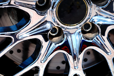
Chromium plating continues to be the coating of choice for many metal finishing applications. Demand for chrome’s bright and lustrous finish continues to grow despite competition from other finishes, such as organic coatings and vapor deposition. Chromium has withstood the competitive challenges due to its unmatched aesthetics as well as its superior technical capabilities, including exceptional corrosion performance, multi-substrate capability and supply-chain factors such as industrial scale, extensive installed applicator base, and long application history and experience. Chromium is widely used in the metal finishing industry for both decorative and hard-chrome plating.
Chromium plating has been carried out on a commercial basis since 1924. In decorative applications, the chrome is plated as a thin (0.25–0.8 μm) layer over nickel to provide an economical and highly corrosion resistant deposit. Most decorative chromium deposits are produced using hexavalent chromium electrolytes. Over the past two decades, processes based on trivalent chromium have gained increasing acceptance in the industry.
Bright chromium can be applied as continuous (regular) or discontinuous layers. Discontinuous deposits are formed by depositing the chromium on microporous (or microcracked) nickel plate. The selection of a continuous or discontinuous layer depends on the level of corrosion resistance required. Failure of bright chromium plate is often due to deep pits developing as a result of corrosion starting at random cracks or pores in the chromium surface. Corrosion is an electrochemical mechanism. Because these cracks or pores are relatively widely spaced, the current developed by the chromium/nickel couple is concentrated at a few points. Deep pits form at these points and rapidly penetrate through the nickel deposit and the component substrate. Inducing micro-discontinuities (microcracks) across the surface spreads the corrosion current and slows the corrosion rate. Typically, articles plated to service condition 1/2 would use regular chromium plate, whereas plating to service condition 3 or above would use a discontinuous layer (ASTM B456).
Decorative Hexavalent Electrolytes
Four types of hexavalent chromium electrolytes are commonly employed:
- sulfate-only catalysts,
- sulfate-fluoride catalysts,
- sulfate-fluoride-organic catalysts
- and self-regulating high speed (SRHS).
The primary differences among the systems are outlined in Table I.
| Type | Single-Catalyst | Dual- Catalyst |
Triple-Catalyst | SRHS |
| Cr03 Concentration, g/L |
450-500 | 180-400 | 250 | 240 |
| Ratio Cr03:H2S04 |
100:1 | 200-300:1 | 160-170:1 | 260-270:1 |
| Catalyst Type | Sulfate only | Mixed sulfate/fluoride | Mixed sulfate/fluoride | Mixed sulfate/organic regulator |
| Cathode Efficiency, % |
8 | 12-18 | 20-25 | 15 |
| Temperature, ºF | 100 | 100-104 | 104 | 104-113 |
| Cathode Current Density, asf |
80-102 | 100-150 | 90-150 | 110-160 |
| Mixed Oxide Level, g/L |
<22 | 10-20 | <12 | <12 |
| Main Features | Simple preparation Tolerant to contamination | Good chromability. Good covering power |
Wide operating parameters. Excellent covering power. |
Tolerant to changes in sulfate. Simple to use. |
The most common electrolytes employed today are based on the dual sulfate/fluoride catalyst. This mixed catalyst has the advantages of improving cathode efficiency, covering power and ability to plate on bright nickel layers when compared to the straight sulfate catalyst type.
Over the last decade, the popularity of the triple catalyst system has grown. This system has characteristics similar to the dual catalyst with advantages of higher cathode efficiencies, wider operating window and improved covering power. To operate these systems, regular analysis of the chromic acid, sulfuric acid and proprietary catalysts concentrations are required.
In markets where access to regular analytical control is limited, the use of SRHS chemistries continues. These systems regulate the active sulfate and catalyst levels ratio to chromic acid by use of proprietary solubilizing agents.
Hexavalent chromium plating solutions have poor deposit distribution. Therefore, when plating to specification, it is necessary to calculate the plating time based on minimum thicknesses required on significant surfaces. A major factor in plating time is the cathode efficiency of chromium plating solutions, which is influenced by the following factors:
Type of electrolyte. This is outlined in Table I. Solutions with higher cathode efficiencies have improved throwing and covering power than the simpler electrolytes. The ability to cover components more evenly is one factor that has led to the popularity of triple catalyst systems.
Solution concentration. The cathode efficiency of a solution rises as chromic acid concentration rises until it reaches a peak at about 250 g/L; thereafter, any increase in concentration lowers cathode efficiency. High-concentration solutions are, however, simpler to control than those of low concentration, are less affected by small changes in sulfate content and will operate with a higher oxide content.
Current density employed. Cathode efficiency varies directly with current density. The higher the current density, the greater the cathode efficiency.
Solution temperature. Cathode efficiency falls with increasing temperature. Higher operating temperatures do, however, permit use of higher current densities. In practice, the optimum temperature is related to the current density employed. With self-regulating solutions, a rise in temperature results in a slight rise in cathode efficiency.
Solution composition. Cathode efficiency is also affected by trivalent chromium content and contaminations such as iron and nickel. Solution efficiency drops as these constituents build up in the solution. Cathode efficiency is also reduced if the solution is out of balance, for example, when addition agents, etc., are lower than the optimum.
Calculation of Plating Times
Any change in current density will generally involve a corresponding adjustment in temperature to keep the solution within the optimum plating range. These changes will also affect cathode efficiency. Table II shows the time needed to produce a deposit averaging 1 μm in thickness at various cathode efficiencies and current densities. These plating times are for average thickness values under uniform current density conditions. In practice there will be considerable variation in current density over the surface and, therefore, the average thickness of chromium applied will be in excess of any minimum thickness requirements.
| Current Density, asf | Cathode Efficiency, % | |||||||
| 8 | 10 | 13 | 14 | 16 | 18 | 20 | 22 | |
| 80 | 20.6 | 16.5 | 13.8 | 11.8 | 10.3 | 9.17 | 8.25 | 7.50 |
| 100 | 16.5 | 13.2 | 11.00 | 9.44 | 8.25 | 7.34 | 6.60 | 6.00 |
| 120 | 13.7 | 11.0 | 9.17 | 7.85 | 6.88 | 6.10 | 5.50 | 5.00 |
| 160 | 10.3 | 8.25 | 6.86 | 5.90 | 5.15 | 4.58 | 4.13 | 3.75 |
| 200 | 8.25 | 6.60 | 5.50 | 4.71 | 4.12 | 3.66 | 3.30 | 3.00 |
| 250 | 6.60 | 5.28 | 4.40 | 3.77 | 3.30 | 1.94 | 2.64 | 2.40 |
| 300 | 5.50 | 4.40 | 3.66 | 3.14 | 2.75 | 2.45 | 2.20 | 2.00 |
| 350 | 4.70 | 3.78 | 3.14 | 2.70 | 2.35 | 2.10 | 1.89 | 1.73 |
| 400 | 4.12 | 3.30 | 2.74 | 2.35 | 2.06 | 1.83 | 1.65 | 1.50 |
| 450 | 3.66 | 2.93 | 2.44 | 2.10 | 1.83 | 16.64 | 1.47 | 1.33 |
| 500 | 3.30 | 2.64 | 2.20 | 1.87 | 1.65 | 1.47 | 1.32 | 1.20 |
| 550 | 3.00 | 2.40 | 2.00 | 1.71 | 1.50 | 1.34 | 1.20 | 1.09 |
| 600 | 2.75 | 2.20 | 1.84 | 1.57 | 1.38 | 1.22 | 1.10 | 1.00 |
| 650 | 2.54 | 2.03 | 1.70 | 1.45 | 1.27 | 1.13 | 1.02 | 0.93 |
| 700 | 2.36 | 1.89 | 1.58 | 1.35 | 1.18 | 1.05 | 0.95 | 0.87 |
Equipment and anodes. Chromium plating solutions are usually contained in PVC-lined tanks. The solution is heated by means of either silica-cased or Teflon electric immersion heaters or steam coils. Tin-lead alloy anodes are generally employed for chromium plating. In a chromium plating tank, the lead anodes serve two purposes: as the positive electrode and to maintain the solution in satisfactory balance by re-oxidizing the trivalent chromium to chromic acid. The anode area should be about 20 percent greater than the area of the normal plating load. When current is passing through the chrome solution gassing will occur at the anodes, which are normally covered with a dark-chocolate-colored film. This film is necessary to ensure that the trivalent chromium produced by electrochemical reduction of the chromium acid at the cathode is re-oxidized to ensure correct solution balance.
Spray control. During electrolysis of the chromic acid, a mist is produced which must be controlled by the use of a suitable chemical mist suppressant, usually in conjunction with local exhaust ventilation. The U.S. Occupational Safety and Health Administration (OSHA) standard for the permissible exposure limit (PEL) for chromic acid mist is 5 μg/cu m with an action level at 2.5 μg/cu m. Proprietary chemical mist suppressants are usually based on perfluoro-octane sulfonates (PFOS). However, these materials are themselves becoming subject to prohibition due to their environmental persistence and bio-accumulative effects in mammals.
PFOS elimination has been a hot topic for the EPA as well as state and local agencies and publicly owned treatment works (POTWs). Recent legislation, which was finalized in September 2012, mandates eliminating PFOS-based fume suppressants by September 21, 2015. Fortunately, commercially viable replacements are available for use in chromic acid solutions. These PFOS-free alternatives are compliant with EPA regulations and can consistently and reliably control spray and mist in chrome electrolytes.
Solution maintenance. Chromium-plating solutions are regularly analyzed for chromic acid, sulfates, catalyst and contamination. Deficiency in chromic acid concentration is restored by the use of a proprietary salt mixture which restores the balance of the solution catalysts at the same time. Deficiency in sulfate is restored by sulfuric acid. If the sulfates are too high due to drag-in from the prior nickel plating stage, the level is reduced by addition of either barium carbonate or hydroxide.
For correct operation, a small proportion of the chromium (1–3 g/L) must be present in the solution as the trivalent radical. Above this level the efficiency of the solution may fall and show narrower bright chromium plating. Over time, metallic contamination such as iron, copper or nickel will build up in solution. These heavy metals are often analytically estimated collectively as “oxides” (Cr2O3, Fe2O3 and so on). Total oxides should not be allowed to rise above 5 percent of the total hexavalent concentration.
Decorative Trivalent Electrolytes
Trivalent chromium plating solutions have become an increasingly popular alternative in the metal finishing industry for a variety of reasons, including increased cathode efficiency and throwing power in addition to lower toxicity. The total chromium metal concentration used in a trivalent chromium solution is significantly lower than that of a hexavalent plating solution—less than 3 oz/gal, versus 15–20 oz/gal for hexavalent solutions.
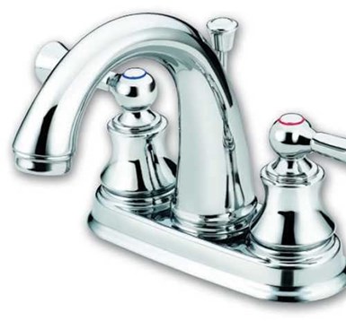
This reduction in metal concentration, in addition to the lower viscosity of the solution, leads to less dragout and wastewater treatment and therefore a cost reduction in the plating process. Trivalent chromium baths, as a result of their excellent throwing power, also produce fewer rejects and allow for increased rack densities in comparison to hexavalent chromium. While trivalent chromium plating has a number of advantages, the system also has a drawback. Specifically, it is difficult to achieve the color of a hexavalent chrome deposit at the same plating rate as hexavalent chrome when utilizing a trivalent chromium electrolyte.
Present trivalent chromium systems either provide a color similar to that of hexavalent chromium at a slower plating rate or a slightly darker color at a plating rate comparable to hexavalent chrome. Development of a trivalent chromium plating solution that could overcome both of these weaknesses is ongoing and crucial if trivalent chromium is to be considered a valid alternative to hexavalent chromium.
Just as different electrolyte options exist for hexavalent chromium plating, so do similar choices exist for plating trivalent chromium. Trivalent chromium processes utilize either a sulfate or chloride-based electrolyte. A comparison of these systems can be seen in Table III.
| Parameter | System type | ||
| Chloride | Sulfate | ||
| System 1 | System 2 | ||
| pH | 2.8 | 3.4 | 3.4 |
| Temperature, ºF | 90 | 130 | 130 |
| Cathode Current | |||
| Density, asf | 80-200 | 40-60 | 100 |
| Anode Current | |||
| Density, asf | 30-60 | 50 | 50 |
| Anode Type | Carbon | Coated Titanium | |
| Filtration | Recommended | Recommended | |
| Purification | Ion Exchange | Dummying, chemical | |
| Color | Darkest | Between 2 | Lightest |
| Deposition rate, µm/min |
0.15-0.25 | <0.03 | 0.02-0.04 |
| Deposit Purity | Lowest | Between 2 | Highest |
Sulfate-based systems plate a deposit of higher purity, which leads to better corrosion protection and a color closer to that of hexavalent chromium. The chemistry of sulfate-based systems is also less corrosive, which prevents deterioration of the plating environment and unplated component areas. Chloride-based systems are capable of plating deposits at a rate similar to that of hexavalent chrome. However, the color is typically darker than hexavalent chrome due to the additives required to achieve the fast plating rate. Chloride systems also utilize graphite (carbon) anodes, which are much less costly than the coated titanium anodes required to operate the sulfate-based trivalent systems.
Equipment and solution maintenance. Trivalent chromium plating solutions operate with equipment similar to that used with hexavalent chromium chemistries. In the event that a plating tank is to be converted from hexavalent to trivalent, all new equipment should be installed to ensure that no contamination of the trivalent chromium solution will occur.
Trivalent chromium solutions should be installed in tanks lined with either PVC or polypropylene. Titanium coils, or titanium-clad, silica-cased or Teflon electric immersion heaters should be used. Continuous filtration is recommended, and carbon (graphite) or coated titanium anodes are required depending on the chemistry.
Plating bath analysis involves regular assessment of the chromium, conductivity salt and complexor concentrations, as well as pH and specific gravity. Ampere-hour dosing of the replenishment components can be utilized for easier operation.
Dark trivalent coatings. Dark coatings are becoming ever more popular in the industry today. The appearance of a dark and shiny finish that can withstand the testing criteria of hexavalent chromium is desired for many applications, and dark trivalent chromium solutions exist that meet both appearance and technical requirements. Many OEMs have incorporated these finishes into their product offerings as a result. These solutions exhibit excellent covering and throwing power, consistent color at a wide range of current densities and the advantage of low-metal operation in comparison to hexavalent chromium. These coatings are capable of exceeding 96 hr of copper-accelerated acetic acid salt spray with no notable change to deposit appearance. These coatings also have an advantage over hexavalent chrome in that they are resistant to calcium chloride corrosion, or Russian Mud.
Hard-Chrome Plating
Hard-chrome plating is normally described as the application of an electroplated chrome deposit with a thickness of greater than 0.0002 inch. Hard-chrome deposits are normally plated to a thickness of 0.0005–0.01 inch, although in theory almost unlimited thicknesses can be achieved.
Commercial hard-chromium plating started in the late 1920s to the early 1930s after work in both the U.S. and Germany using a bath based on chromic and sulfuric acids at a ratio of 100:1. In the intervening years the basic formulation of the electroplating bath for hard-chrome plating has not altered, and although there have been improvements made to the technology a lot of electroplaters still use this original chemistry.
The reason for the growth of hard-chrome plating into the multimillion-dollar business it is today is that the chrome deposit from these solutions has a combination of properties that has not been matched by any of the later technologies offered and tested. These properties include:
- High hardness
- Low coefficient of friction
- Excellent wear resistance
- Excellent corrosion resistance (especially in oxidizing atmospheres).
Hard chrome can be applied at a very low cost compared to alternatives, and it can plate on a wide variety of substrates. This explains why, despite environmental issues, hard chrome continues to be widely specified and used.
The ability to electroplate chrome metal from a hexavalent chrome solution theoretically is not possible; however, it is achieved by using an acid radical as a catalyst. This catalyst has historically been sulfate, although others such as fluoride can also be used.
Types of hard chrome. There are three main types of hard chrome in operation. The properties of these systems are given in Table IV. The plating rate of each type of solution depends on the current density and efficiency of the plating solution.
| Sulfate Only(Sargeant) | Fluoride/Sulfate | Acid/Sulfate | |
| Chromic Acid Concentration, oz/gal | 32 | 32 | 32 |
| Sulfate concentration, oz/gal | 0.32 | 0.16 | 0.35 |
| CrO3:SO4 ratio | 100:1 | 200:1 | 90:1 |
| Cathode Efficiency, % | 10-13 | 22.25 | 23-26 |
| Hardness, HV | 800-1,000 | 950-1,050 | 1,000-1,200 |
| Micro-cracking, cracks/inch | 0-1,250 | 1,250-2,500 | 2,500-5,000 |
| Brightness | Semi-bright | Bright | Very Bright |
| Temperature, ºF | 130 | 130 | 140 |
| Cathode Current Density, A/in2 | 1.0-4.0 | 1.0-6.0 | 1.0-6.0 |
| Anode Current Density, A/in2 | 0.5-3.0 | 0.5-3.0 | 0.5-3.0 |
Sargeant solution consists of chromic acid and sulfate at a ratio of about 100:1. This bath is often offered as a self-regulated process where the controlled solubility of a chosen sulfate compound is used to maintain the correct ratio in the solution. These baths are cheap to run, but have low cathode efficiency and give lower hardness and generally worse corrosion protection than more modern systems.
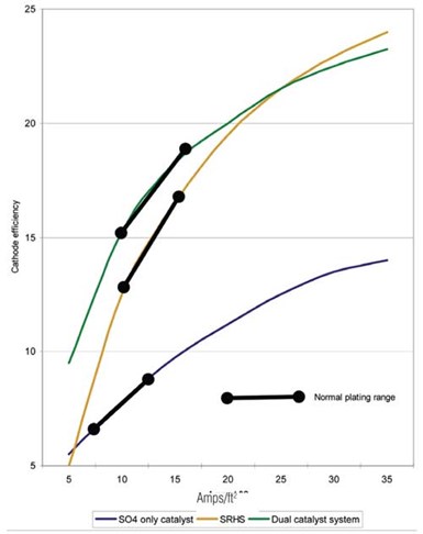
Fluoride-catalyzed processes are used with sulfate. They give a much harder as-plated deposit and have much higher cathode efficiency than Sargeant solution, and thus have a higher plating rate.
Fluoride-catalyzed processes are used with sulfate. They give a much harder as-plated deposit and have much higher cathode efficiency than Sargeant solution, and thus have a higher plating rate. The down side is that their chemistry is much more aggressive to both equipment and the plated parts, hence metallic contamination is a serious issue. This has limited their use although they have found some specific applications where they are used extensively.
Organic acid salts can also be used in conjunction with sulfate in the chrome solutions and have become, for most, the preferred option. They have high efficiency, plate very hard deposits and due to the high level of micro-cracking found with these systems they offer good corrosion protection. Some of the earlier systems used have a negative effect on the rate of anode corrosion, but more modern chemistries show similar anode corrosion to the early Sargeant processes.
Equipment. Hard-chrome plating solutions should be used in tanks lined with a flexible polyvinyl chloride. Koroseal is a typical example of this. Lead-lined tanks are not recommended.
Any required heating or cooling equipment should be constructed of PTFE or a similar fluorocarbon, tantalum or titanium; although use of titanium is not recommended if using a fluoride catalyzed process.
The power used for hard-chrome plating should have a smoothed wave, because ripple can cause many technical issues in a hard chrome solution. Power supplies should be capable of up to 15 V for normal applications. Because large currents and voltages are used, the bus bars should be capable of carrying the current required without overheating. It is also important to insulate all conducting materials from external power to reduce the risk of stray currents being formed.
For most systems, the use of tin-lead anodes (7 percent Sn) is recommended. The anode area should be about 150 percent of the cathode area to reduce the risk of an increase in the trivalent chrome concentration.
In some circumstances lead/antimony anodes are used, as these are more rigid than tin/lead and so are less likely to stretch in larger tanks. These anodes should not be used with fluoride-based systems, because they corrode more quickly and have a lower conductivity than traditional tin/lead anodes.
In some countries, platinum-coated titanium anodes are increasingly being used. These cost substantially more initially but often save money, as they can last up to 10 years and they do not generate lead chromate sludge that can be difficult to remove. It is important when using these anodes to maintain a small amount of lead in the solution; without this, the trivalent chrome concentration can increase leading to quality issues.
Due to the poor throwing power of hard chrome plating solutions, the use of auxiliary anodes and shields is common and is one of the major skills required by hard chrome electroplaters.
Extraction equipment is needed because hard chrome plating is very inefficient electrochemically and generates a considerable amount of hydrogen gas at the cathode. This can give a very heavy “mist” from the plating solution. As previously mentioned, permissible exposure limits have recently been reduced and are very low. For this reason, it is very important to provide excellent extraction. It is also possible to use surfactants to reduce the surface tension of the plating tank.
Operation. The operation of a hard-chrome solution is not complex, but there are certain aspects that must be controlled. These are: chromic acid concentration, sulfate concentration, catalyst concentration (if using more than sulfate), temperature and metallic oxide contamination such as iron, nickel copper or trivalent chrome; this is important in ensuring the best efficiency from the plating solution (see the section on contamination).
Substrates. It is possible to plate most substrates in hard chrome by altering the pretreatment used. Substrates commonly plated include steel, hardened steel, cast iron, bronze (used as an undercoat to give corrosion protection) and aluminum. It is advantageous to use a fluoride-catalyzed bath when plating on hardened steels or nickel alloys if immersion or anodic activation is being used, but it is possible to plate these in the other catalyzed systems using separate activation and a cathodic wash.
It is also possible to plate hard chrome onto previously plated hard chrome or other plated finishes. One of these is electroless nickel, where a combination of the hard chrome wear and hardness with the even thickness of the EN can provide many advantages.
Contamination. All chrome solutions build up in contaminants, and it is important to minimize these as they have a negative effect on the quality of the plating. This is more true with hard chrome plating than decorative chrome, as there is minimal drag-out in hard chrome and thus contaminants tend to increase faster in these solutions.
As cations build up in the plating solution, they reduce the conductivity of the solution leading to an increase in the voltage required to maintain a current density and a potential loss of efficiency.
It is possible to remove metallic contamination by using a porous pot technology, electrodialysis or ion exchange. Ion exchange has to be used with a dilute solution to avoid attack on the resin, so it is more commonly used to purify the drag out solution which can then be added back to the plating tank.
Properties. Hard chrome offers a hard, lubricious, corrosion-resistant and wear-resistant coating. One of the main reasons for its good performance in corrosion testing is that the deposit is micro-cracked; if the deposit is thick enough (normally >1 mil) the cracks in the deposit do not reach the substrate and corrosion performance is markedly improved.
Macro-cracks, on the other hand, can result in accelerated corrosion. Generally if a deposit is macro-cracked it is neither as hard nor as wear resistant as a micro-cracked process. Micro cracking also is advantageous in lubricated applications, as the lubricant is stored in the cracks. Table V gives a summary of some of the performance characteristics of hard chrome deposits.
| Property | Typical Performance |
| Taber Wear | 2-3 mg/1,000 cycles |
| Coefficient of Friction | 0.15-0.40 on steel |
| Magnetism | Not magnetic |
| Melting Point | 1,610ºC |
| Ductility | 0.1% |
Related Content
How to Choose Between Sulfate and Chloride-Based Trivalent Chromium
There are several factors to consider when choosing between sulfate and chloride-based baths for trivalent chromium plating. Mark Schario of Columbia Chemical discusses the differences and what platers should keep in mind when evaluating options.
Read MorePrevent Plating Problems with Critical Inspections
Tanks and their contents should be regularly inspected visually and analytically. When a quality issue arises, it is important to quickly pinpoint where the main problem is by checking which parameter is out of line.
Read MoreUnderstanding and Managing White Spots on Anodized Aluminum
Having trouble with spotting defects when anodizing? Taj Patel of Techevon LLC offers a helpful overview of the various causes of white spots and potential solutions.
Read MoreAlkaline Cleaning Guide
Gregg Sanko, Senior Chemist, Oakite Products, Inc. provides an overview of the alkaline cleaning process.
Read MoreRead Next
Episode 45: An Interview with Chandler Mancuso, MacDermid Envio Solutions
Chandler Mancuso, technical director with MacDermid Envio discusses updating your wastewater treatment system and implementing materials recycling solutions to increase efficiencies, control costs and reduce environmental impact.
Read MoreEducation Bringing Cleaning to Machining
Debuting new speakers and cleaning technology content during this half-day workshop co-located with IMTS 2024.
Read MoreDelivering Increased Benefits to Greenhouse Films
Baystar's Borstar technology is helping customers deliver better, more reliable production methods to greenhouse agriculture.
Read More


