Electrocodeposition of MCrAlY Coatings for Advanced Gas Turbine Applications - 6th Quarterly Research Report
This NASF-AESF Foundation research project report covers the sixth quarter of project work (April-June 2019) on this AESF Foundation Research project at the Tennessee Technological University.
Editor’s Note: This NASF-AESF Foundation research project report covers the sixth quarter of project work (April-June 2019) on an AESF Foundation Research project at the Tennessee Technological University, Cookeville, Tennessee. A printable PDF version of this report is available by clicking HERE.
Summary: In the second quarter of Year 2, the effect of the particle size of ball-milled CrAlY powders on electro-codeposited Ni-CrAlY composite coatings was studied. Two rotating barrel configurations, i.e., the open and closed barrels, were utilized in the electro-codeposition experiments. For the open barrel covered with a nylon membrane, smaller particles (< 5 μm) were able to escape from the barrel, likely due to the woven structure of the mesh and the high aspect ratio of the ball-milled powder. The particle incorporation increased from less than 20 vol% in the initial plating runs to ≥30 vol% in the subsequent runs after the smaller particles escaped from the barrel. For the closed barrel, the use of the porous membrane was eliminated and thus the loss of small particles, leading to more consistent particle distribution in the coatings from run to run. Regardless of the barrel configuration, the increase in CrAlY particle size led to an increase in particle incorporation in the coating. The closed barrel configuration is more suitable for the investigation of the particle size effect and will be used in our future studies.
Technical report
I. Introduction
To improve high-temperature oxidation and corrosion resistance of critical superalloy components in gas turbine engines, metallic coatings such as diffusion aluminides or MCrAlY overlays (where M = Ni, Co or Ni+Co) have been employed, which form a protective oxide scale during service.1 The state-of-the-art techniques for depositing MCrAlY coatings include electron beam-physical vapor deposition (EB-PVD) and thermal spray processes.1 Despite the flexibility they permit, these techniques remain line-of-sight which can be a real drawback for depositing coatings on complex-shaped components. Further, high costs are involved with of the EB-PVD process.2 Several alternative methods of making MCrAlY coatings have been reported in the literature, among which electro-codeposition appears to be a more promising coating process.
Electrolytic codeposition (also called “composite electroplating”) is a process in which fine powders dispersed in an electroplating solution are codeposited with the metal onto the cathode (specimen) to form a multiphase composite coating.3,4 The process for fabrication of MCrAlY coatings involves two steps. In the first step, pre-alloyed particles containing elements such as chromium, aluminum and yttrium are codeposited with the metal matrix of nickel, cobalt or (Ni,Co) to form a (Ni,Co)-CrAlY composite coating. In the second step, a diffusion heat treatment is applied to convert the composite coating to the desired MCrAlY coating microstructure with multiple phases of β-NiAl, γ-Ni, etc.5
Compared to conventional electroplating, electro-codeposition is a more complicated process because of the particle involvement in metal deposition. It is generally believed that five consecutive steps are engaged:3,4 (i) formation of charged particles due to ions and surfactants adsorbed on particle surface, (ii) physical transport of particles through a convection layer, (iii) diffusion through a hydrodynamic boundary layer, (iv) migration through an electrical double layer and finally, (v) adsorption at the cathode where the particles are entrapped within the metal deposit. The quality of the electro-codeposited coatings depends upon many interrelated parameters, including the type of electrolyte, current density, pH, concentration of particles in the plating solution (particle loading), particle characteristics (composition, surface charge, shape, size), hydrodynamics inside the electroplating cell, cathode (specimen) position, and post-deposition heat treatment if necessary.3-6
There are several factors that can significantly affect the oxidation and corrosion performance of the electrodeposited MCrAlY coatings, including: (i) the volume percentage of the CrAlY powder in the as-deposited composite coating, (ii) the CrAlY particle size/distribution, and (iii) the sulfur level introduced into the coating from the electroplating solution. This three-year project aims to optimize the electro-codeposition process for improved oxidation/corrosion performance of the MCrAlY coatings. The three main tasks are as follows:
- Task 1 (Year 1): Effects of current density and particle loading on CrAlY particle incorporation.
- Task 2 (Year 2): Effect of CrAlY particle size on CrAlY particle incorporation.
- Task 3 (Year 3): Effect of electroplating solution on the coating sulfur level.
In this reporting period, the effect of the particle size of ball-milled CrAlY powders was studied. Two barrel configurations were utilized and the resultant coatings were compared.
II. Experimental Procedure
2.1. Open and closed rotating barrel systems
Two rotating barrel systems were utilized in the electro-codeposition experiments. The open barrel configuration (Fig. 1) consisted of a barrel made of polypropylene ribbing. The outer wall was covered by a nylon membrane, which allowed the exchange of the solution between the inside of the barrel and the surrounding plating bath in the tank while keeping the powder in the barrel. To rotate the barrel, a gear set driven by a variable speed DC motor was attached on one end. The barrel (approximately 200 mL in volume) and gear set were then suspended in a 5-L tank of plating solution such that the barrel was fully submerged. Specimens were placed longitudinally and centered on the barrel’s axis of rotation. A sample mount coupled the specimen to the barrel, ensuring both would rotate together. A flexible metal wire (isolated from the solution through Teflon tubing) was attached to the sample to connect it to the power supply. A solid nickel anode was placed outside of the barrel along with a mechanical stirrer and heating coil. The 2-kilowatt heating system was used to control the bath temperature at 50°C ± 1.5°C.
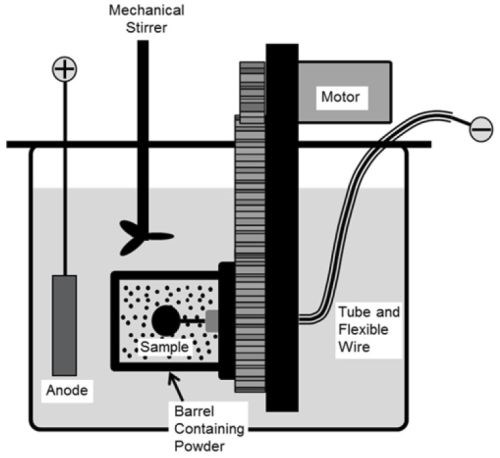
Figure 1 - Schematic of the open barrel system.
In contrast to the open barrel, a closed barrel was constructed with solid polypropylene walls instead of solid ribbing covered with the porous membrane. A more detailed description of this barrel configuration is given in US Patent Application 62349778.7 The specimen was placed along the axis of rotation, and the anode was attached to the barrel’s inner surface. Since the plating solution was stored inside the barrel, no additional plating tank was needed. The solution was heated by heat tape wrapped around the barrel’s outer surface, and the temperature was controlled to an accuracy of ±1°C using a temperature controller.
2.2. Sample preparation, electro-codeposition parameters, and coating characterization
Pure Ni, Ni-based superalloys, and 304 stainless steel were used as substrates. Disc specimens (1.6 mm thick, ~17 mm in diameter) were ground to #600 grit using SiC grinding papers, followed by grit blasting using #220 Al2O3 grit. The specimens were then ultrasonically cleaned in hot water and acetone. Ball-milled CrAlY powder with and without water elutriation treatment were employed in the electro-codeposition experiments. Details of powder preparation can be found in the 2019-Q1 Report. Table 1 summarizes the particle size distribution. Watts nickel or nickel-cobalt plating solution was utilized and the particle concentration in the solution was kept around 20 g/L. The pH of the plating solution was maintained at 3.0-4.0, and the barrel rotation speed was set at 4-7 RPM. Current densities ranging from 5 to 20 mA/cm2 were used. The specimens were plated for different times, depending on the applied current density. The Ni-CrAlY composite coatings were characterized by scanning electron microscopy (SEM) equipped with energy dispersive spectroscopy. Prior to metallographic sample preparation, the specimens were copper-plated to improve edge retention. To determine the volume fraction of the incorporated CrAlY particles, multiple backscattered electron images were taken from different locations along the coating cross-section, which were then processed using the ImageJ software. The brightness and contrast of the images were adjusted by setting a proper threshold such that the particles were separated from the background. The area fraction of the CrAlY particles was determined, which was assumed equivalent to its volume fraction.
III. Results and Discussion
As shown in Table 1, the D10, D50, and D90 values of the ball-milled CrAlY powder were 1.6 mm, 5.6 mm and 14.9 mm, respectively. About 50 vol% of the powder was comprised of particles smaller than 5.6 mm. For the open barrel, although the nominal mesh size of the nylon membrane was reported to be 1 mm, particles larger than 1 mm (up to 5 mm) were able to escape from the barrel, likely due to the woven structure of the mesh and the high aspect ratio of the ball-milled powder. When the open barrel was used, significant loss of smaller particles through the membrane wall occurred for the first two plating runs, and the particle size was stabilized in the subsequent runs if no fresh powder was added to the barrel. Figure 2 compares the Ni-CrAlY coatings plated before and after the loss of smaller particles. The particle incorporation increased from less than 20 vol% in the initial plating runs (Fig. 2a) to ≥30 vol% (Fig. 2b) in the subsequent runs after the smaller particles escaped from the barrel.
Table 1 - Particle size distribution of the CrAlY powders used in the electro-codeposition experiments.

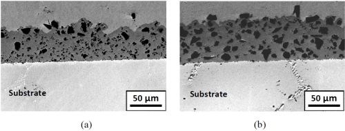
Figure 2 - SEM cross-sections of Ni-CrAlY coatings plated in the open barrel: (a) before and (b) after the escape of smaller particles.
It was clear that the loss of smaller particles was beneficial for increasing the particle incorporation. However, corrections for the particle concentration in the solution (via adding powder) were required after each plating run in order to keep the particle loading consistent. The open barrel configuration was therefore not ideally suited for the study of particle size effect, particularly for the powders containing particles £5 mm.
The closed barrel system eliminated the need for the porous membrane and thus the loss of small particles. Smaller particles were observed in the coating deposited after the fresh powder was loaded in the barrel (Fig. 3a), as well as in the coating plated in the subsequent runs (Fig. 3b). Particle distribution in the Ni-CrAlY coatings was more consistent from run to run. The difference between Fig. 2b and Fig. 3b is obvious, and fewer smaller particles can be seen in the coatings plated in the open barrel.
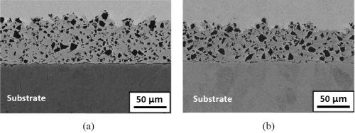
Figure 3 - SEM cross-sections of Ni-CrAlY coatings plated in the closed barrel: (a) the first run; (b) subsequent runs.
To reduce the amount of smaller particles in the coating deposited using the closed barrel, water elutriation** was employed. The particle distribution after elutriation is also given in Table 1. Particles smaller than 5 µm were effectively removed, and the D10 value of the powder after water elutriation was 6.4 mm, indicating that only 10 vol% of the powder exhibited a particle size of less than 6.4 mm. The Ni-CrAlY coating deposited using the water-elutriated powder is presented in Fig. 4. The resultant coating (Fig. 4) resembled the one plated in the open barrel after the loss of smaller particles (Fig. 2b).
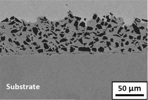
Figure 4 - SEM cross-section of the Ni-CrAlY coating plated in the closed barrel using the water-elutriated powder.
With the closed barrel configuration, the increase in particle size also led to an increase in particle incorporation in the coatings. For the non-elutriated powder, the Ni-CrAlY coatings had a particle incorporation of ~25 vol%, while the particle incorporation in the coatings deposited using the elutriated powder was around 35 vol%. It can be concluded that the increase in particle size is beneficial for the particle incorporation, regardless of the barrel configuration.
There are several benefits associated with the closed barrel configuration. First, the size of the particles that can be incorporated in the composite coatings is not limited by the pore size of the nylon membrane, and codeposition of smaller particles (even nanoparticles) is thus possible with this configuration. Second, the amount of plating solution required is significantly reduced, which can be particularly useful for exploration of new solutions. Clearly, the closed barrel configuration is more suitable for the investigation of the particle size effect and will be used in our future studies.
References
1. G.W. Goward, Surf. Coat. Technol., 108-109, 73-79 (1998).
2. A. Feuerstein, et al., J. Therm. Spray Technol., 17 (2), 199-213 (2008).
3. C.T.J. Low, R.G.A. Wills and F.C. Walsh, Surf. Coat. Technol., 201 (1-2), 371-383 (2006).
4. F.C. Walsh and C. Ponce de Leon, Trans. Inst. Metal Fin., 92 (2), 83-98 (2014).
5. Y. Zhang, JOM, 67 (11), 2599-2607 (2015).
6. B.L. Bates, J.C. Witman and Y. Zhang, Mater. Manuf. Process, 31 (9), 1232-1237 (2016).
7. J.C. Witman, Y. Zhang, and B.L. Bates, “Apparatus Used for Producing Coatings,” Patent Application #62349778 (2016).
Past project reports
1. Quarter 1 (January-March 2018): Summary: NASF Report in Products Finishing; NASF Surface Technology White Papers, 82 (12), 13 (September 2018); Full paper: http://short.pfonline.com/NASF18Sep1.
2. Quarter 2 (April-June 2018): Summary: NASF Report in Products Finishing; NASF Surface Technology White Papers, 83 (1), 13 (October 2018); Full paper: http://short.pfonline.com/NASF18Oct1.
3. Quarter 3 (July-September 2018): Summary: NASF Report in Products Finishing; NASF Surface Technology White Papers, 83 (3), 15 (December 2018); Full paper: http://short.pfonline.com/NASF18Dec1.
4. Quarter 4 (October-December 2018): Summary: NASF Report in Products Finishing; NASF Surface Technology White Papers, 83 (7), 11 (April 2019); Full paper: http://short.pfonline.com/NASF19Apr1.
5. Quarter 5 (January-March): Summary: NASF Report in Products Finishing; NASF Surface Technology White Papers, 83 (10), 11 (July 2019); Full paper: http://short.pfonline.com/NASF19Jul1.
About the author

Dr. Ying Zhang is Professor of Mechanical Engineering at Tennessee Technological University, in Cookeville, Tennessee. She holds a B.S. in Physical Metallurgy from Yanshan University (China)(1990), an M.S. in Materials Science and Engineering from Shanghai University (China)(1993) and a Ph.D. in Materials Science and Engineering from the University of Tennessee (Knoxville)(1998). Her research interests are related to high-temperature protective coatings for gas turbine engine applications; materials synthesis via chemical vapor deposition, pack cementation and electrodeposition, and high-temperature oxidation and corrosion. She is the author of numerous papers in materials science and has mentored several Graduate and Post-Graduate scholars.

Dr. Jason C. Whitman is a Materials Lab Engineer at National Aerospace Solutions, LLC at Arnold AFB, Tennessee. His primary work with AESF Foundation Research Project R-119, was as a Graduate Research Assistant at Tennessee Technological University in Cookeville, Tennessee, from which he earned a B.S. degree in Mechanical Engineering (2012), and a Ph.D. in Mechanical Engineering in (2018).
*Corresponding author:
Dr. Ying Zhang, Professor
Department of Mechanical Engineering
Tennessee Technological University
Cookeville, TN 38505-0001
Tel: (931) 372-3265
Fax: (931) 372-6340
Email: yzhang@tntech.edu
** Elutriation is a process to separate particles based on size, shape and density, using a stream of gas or liquid flowing in an upward direction opposite to the direction of gravity sedimentation.
Related Content
AESF Heritage: SUR/FIN 2000 – European Academy of Surface Technology: Copper Microelectrodeposition: The Influence of Different Additives on Growth in Microprofiles
In this work, a pH 3.0, 0.8M copper sulfate electrolyte was used for plating onto both blanket and patterned silicon wafers. This novel electrolyte, proposed by U. Landau, involves a number of beneficial effects with respect to the conventional bath.
Read MoreCalculating Applied Media Force During Vibratory Finishing
What appear to be identically set-up vibratory bowls will finish identical loads of parts in varying time cycles. This paper offers a new technique to better predict what the operator will produce, by measuring the force applied to the parts. It is the efficiency of that force which controls the efficiency and speed of the refinement cycle.
Read MoreMaterial Database Enables Coating Thickness Measurement Without Calibration
The database from Coatmaster AG has calibrations of over 400 different RAL colors.
Read MoreRead Next
Education Bringing Cleaning to Machining
Debuting new speakers and cleaning technology content during this half-day workshop co-located with IMTS 2024.
Read MoreDelivering Increased Benefits to Greenhouse Films
Baystar's Borstar technology is helping customers deliver better, more reliable production methods to greenhouse agriculture.
Read MoreEpisode 45: An Interview with Chandler Mancuso, MacDermid Envio Solutions
Chandler Mancuso, technical director with MacDermid Envio discusses updating your wastewater treatment system and implementing materials recycling solutions to increase efficiencies, control costs and reduce environmental impact.
Read More


