Electrodeposition of Ni-Fe-Mo-W Alloys - Part 7
Seventh Quarterly Report - AESF Research Project #R-117. This NASF-AESF Foundation research project report covers the seventh quarter of project work (July-September 2014).
by Prof. E.J. Podlaha-Murphy,* A. Kola and Rui Wu, Northeastern University, Boston, Massachusetts, USA
Editor’s Note: This NASF-AESF Foundation research project report covers the seventh quarters of project work (July-October 2014). Progress on the previous quarters has been published in summary in the NASF Report in Products Finishing and in full at www.pfonline.com.** A printable PDF version is available by clicking HERE.
Introduction
The project, initiated in January 2013, addresses the induced codeposition of molybdenum and tungsten alloys with nickel and iron having a focus on developing a toolbox of plating conditions to deposit different combinations of Ni, Fe, Mo and W. This paper covers progress made during the seventh quarter. Work was focused on the change of composition of Ni-Mo-W alloys from non-ammonium containing electrolytes with an eye towards improving the current efficiency.
Through NASF-AESF Foundation funding, several students, both graduate and undergraduate, have gained experience in surface finishing research. In this period, there was a change in student participation. A new student, Rui Wu, has joined our research effort on Ni-Mo-W alloys. Graduate student Avinash Kola has continued work on the influence of deposition conditions on the properties of the Ni-W alloys.
Effect of operating variables on Ni-Mo-W current efficiency
From our past work, one detracting feature noted is that without the use of ammonium-containing species in the electrolyte, the current efficiency was particularly low, ~10%. In an effort to improve the current efficiency in our boric acid-citrate electrolyte, two variables were examined: the electrolyte temperature and tungstate composition. These two variables were identified previously as having a significant change on the deposit thickness, hence current efficiency.
Experimental
Two types of electrode experimental set-ups were used: (a) a rotating cylinder electrode (RCE) and (b) a rotating cylindrical Hull cell (RHC) as the working electrode. The counter electrode in both cases was a DSA anode. The electrolyte contained 0.15M nickel sulfate, 0.005M sodium molybdate, 0.375M sodium citrate and 0.1M boric acid with various amounts of sodium tungstate (0.01, 0.05 and 0.1M). Five different electrolyte temperatures were examined: 25, 35, 45, 55 and 65°C. The electrolyte pH was maintained at 7.0 with sodium hydroxide and sulfuric acid additions.
Rotating cylinder electrode (RCE)
The RCE was used to assess the current-potential relationship (i.e., polarization curves). The use of an RCE ensures uniform mixing near the electrode surface with a fully developed turbulent flow profile. The electrode diameter was 0.6 cm, and the electrode length was 1 cm. The rotation rate was constant at 500 rpm and the sweep rate was 10 mV/sec.
Rotating cylindrical Hull cell (RCHC)
A rotating Hull cell was used to survey the current density for the different electrolyte tungstate concentrations and temperatures. In contrast to a conventional Hull cell, the cylindrical design provides a better control of the mixing environment and hence boundary layer thickness. The RCHC was first introduced by Madore and Landolt,*** and was designed to mimic the current distribution of the original Hull cell. The current distribution is created by placing the anode outside a plastic shield that surrounds the cathode. Figure 1 is a sketch of the RCHC used here with the dimensions of the cell. Hence, this design merges the advantages of the rotating cylinder electrode with a controlled, non-uniform current distribution as in the Hull cell. Deposits were analyzed by x-ray fluorescence (XRF).
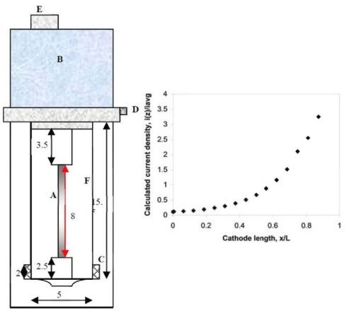
Figure 1 - Schematic diagram of a rotating Hull cell (measurements in cm) with the current distribution expected when reactions are facile (primary current density): (A) working electrode, (B/E) motor, (C) concentric anode, (D) electrical contact, (F) plastic shield.
Results
Figure 2 shows polarization curves at different electrolyte temperatures. The overall current density does indeed increase with electrolyte temperature, which may suggest a positive step forward in improving current efficiency. However, an increase in temperature can also increase the side reaction rate, and hence without another measure of mass deposited, this figure alone cannot predict whether the current efficiency actually improves with temperature.
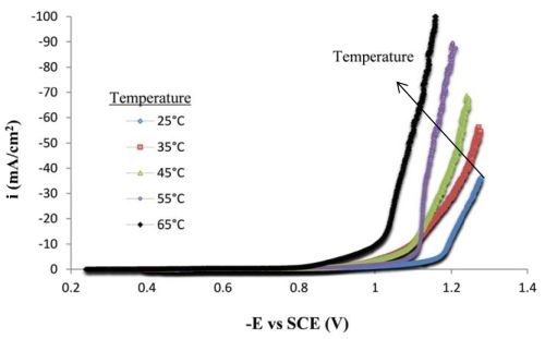
Figure 2 - Polarization curves of the Ni-Mo-W electrolyte at different temperatures on a RCE, 500 rpm (0.1M sodium tungstate).
To this end, the RCHC was used to survey the deposit composition and mass. Deposits were generated by applying an average current density of 67 mA/cm2 for 25 min at 500 rpm, resulting in a low current density (~7 mA/cm2) at one end of the electrode and a high current density (~ 200 mA/cm2) at the other end. Figure 3 shows the concentration change along one electrode. Assuming that field effects dominate, the x-axis is an estimate of the local current density. At room temperature (25°C), a Ni-Mo-W alloy (53.8 wt% Ni, 30.7 wt% Mo, 15.5 wt% W) composition was obtained in the low current density region. As the current density increased the amount of tungsten decreased. At high current densities the thickness is so low that there may be considerable error in the composition analyses. Focusing on the low current density region, as the temperature increased the molybdenum content in the deposit decreased, and the tungsten content increased.
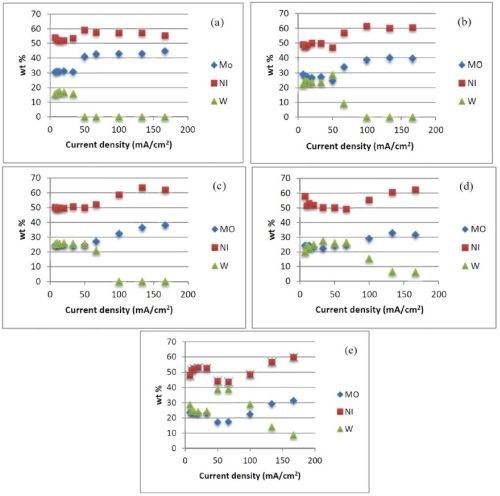
Figure 3 - Effect of temperature and current density on the Ni-Mo-W deposit composition at (a) 25°C, (b) 35°C, (c) 45°C, (d) 55°C, (e) 65°C (0.1M sodium tungstate).
The current efficiency as a function of current density was determined from the XRF measurements. At room temperature, we observed low current efficiency. With an increase in temperature from 25°C to 65°C, there was an improvement in current efficiency when the applied cathodic current density was less than 50 mA/cm2. Comparing Figs. 4 (a thru e) with Figs. 3 (a thru e), the improvement in efficiency correlates with a decrease in molybdenum content in the deposit. We are currently examining the potential values at the higher current density regions in order to calculate the partial current densities of the metal reaction rates with potential to get a better quantitative measure of the change of the reaction rates.
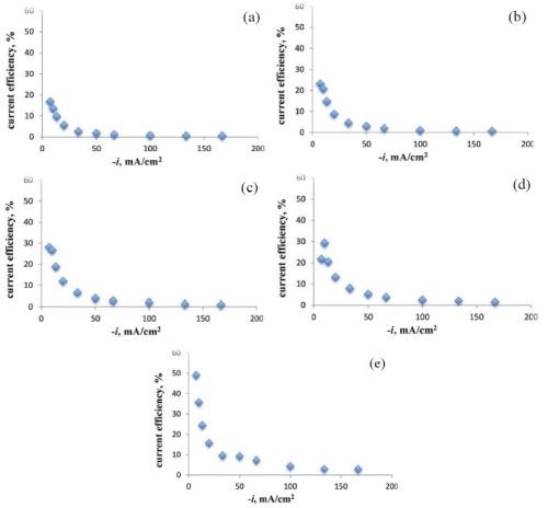
Figure 4 - Effect of temperature and current density on current efficiency during Ni-Mo-W deposition at (a) 25°C, (b) 35°C, (c) 45°C, (d) 55°C, (e) 65°C.
The one negative feature that has plagued our previous results is the formation of cracks. Figure 5 shows optical images that characterize the surface at low and high current densities for a low temperature deposit (25°C) and a high temperature deposit (65°C), at each end of the cathode rod used in the RCHC. Considerable micro-scale cracks were observed at 65°C when the current density was large (Fig. 5d). In the low current density range, fewer micro-scale cracks were observed at the lower temperature (Fig. 5a). Keeping the cathodic current density low, below 10 mA/cm2, but at higher temperature (Fig. 5c), the deposit was not crack-free, but did exhibit a lower crack density when at the higher current density range, and with improved current efficiency. We plan to examine this current density region in more detail.
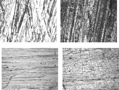
Figure 5 - Optical images of deposits on the RCHC at (a) the low current density end at 25°C, (b) the high current density end at 25°C, (c) the low current density end at 65°C and (d) the high current density end at 65°C.
The influence of the tungstate concentration was also examined. Figure 6 shows polarization curves for three different tungstate concentrations. In all cases, when the applied cathodic current density was larger than ~50 mA/cm2, there was a change in slope that would be consistent with the onset of the side reaction from water reduction.
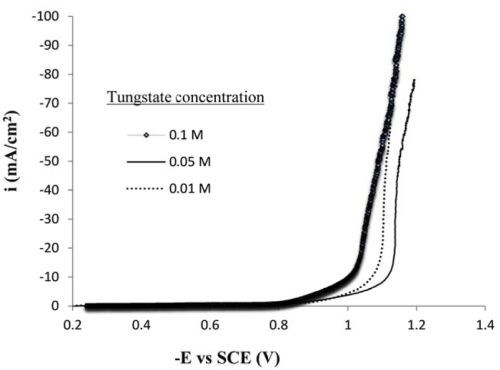
Figure 6 - Polarization curves for the Ni-Mo-W electrolyte containing different sodium tungstate concentration, on a RCE, 500 rpm, 65°C.
Experiments were carried out with the RCHC at the same rotation rate used in the above studies. The sodium tungstate concentration in the electrolyte was varied between 0.1 and 0.01M, at a constant temperature (65°C), keeping the remaining deposition conditions the same. As the tungsten concentration in the electrolyte was decreased (Fig. 7), there was less tungsten in the resulting deposit, but it was not entirely replaced by molybdenum entirely. The molybdenum content did increase, but so did that of the nickel.
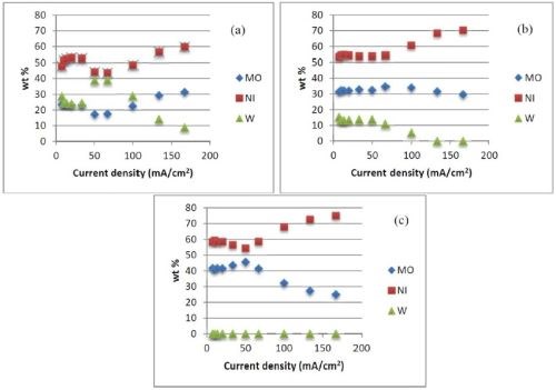
Figure 7 - Effects of sodium tungsten concentration and current density on deposit composition: (a) 0.1M, (b) 0.05M, (c) 0.01M; (65°C).
With more molybdenum codepositing, the current efficiency decreased (Fig. 8), a behavior that is generally consistent when depositing molybdenum and tungsten together. The more molybdenum, the lower the current efficiency, as it seems to better catalyze the side reaction, compared to tungsten.
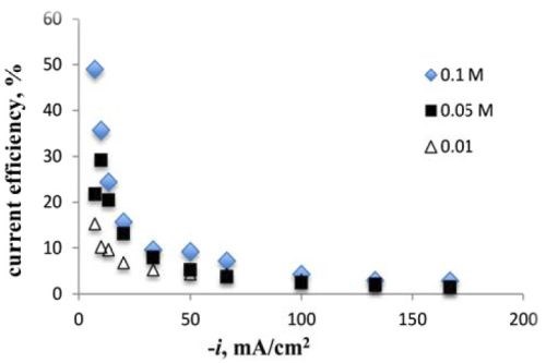
Figure 8 - Current efficiency versus sodium tungstate concentration (65°C).
Conclusion
The electrolyte temperature had the most significant effect on the current efficiency, although the deposit composition changed. The tungsten content in the deposit increased with an increase in temperature. Lowering the concentration of sodium tungstate in the electrolyte reduced the amount of tungsten in the deposit. There was no detectable tungsten present at a 0.01M sodium tungstate concentration, at 65°C.
Presentations [where AESF was acknowledged for support (work from prior reports)]:
1. A. Kola and E.J. Podlaha, Electrodeposition of Ni-W, Ag-W and Ag-Ni-W alloys from Citrate-Thiourea electrolytes, presented at the 224th Electrochemical Society (ECS) Meeting, (A1) San Francisco, CA, October 2013.
2. M. Silva, A. Alamansure, K. Duarte, A. Kola and E. Podlaha “Plating of NiW, NiMo and NiMoW with and without Fe: Induced Codeposition Mechanism,” presented at SUR/FIN 2014, Cleveland, OH, June 11, 2014.
3. E.J. Podlaha, A. Kola and S. Sun, “NiWAg, NiWMo and NiW Electrodeposition,” presented at SUR/FIN 2013, Chicago, IL, June 12, 2013.
4. S. Sun and E. J. Podlaha, “Examination of Induced Codeposition by Intensity Modulated Photocurrent Spectroscopy (IMPS),” presented at the Gordon Research Conference on Electrodeposition, Biddeford, ME, July 27-31, 2014 (poster).
5. A. Kola and E. J. Podlaha, “A First Investigation of Ag-Ni-W Ternary Alloy Electrodeposition,” presented at the Gordon Research Conference on Electrodeposition, Biddeford, ME, July 27-31, 2014 (poster).
6. S. Sun and E.J. Podlaha, “Examination of NiW Induced Codeposition by Intensity Modulated Photocurrent Spectroscopy (IMPS),” presented at the 225th Electrochemical Society (ECS) Meeting, (E3) Orlando, FL, May 2014.
About the authors:


Footnotes:
*Corresponding author:
Prof. E.J. Podlaha-Murphy, Professor of Chemical Engineering, Northeastern University, Boston, Massachusetts 02115
Phone: (617) 373-3796
E-mail: e.podlaha-murphy@neu.edu
**Quarter 1 (January-March 2013): NASF Report in Products Finishing; NASF Surface Technology White Papers, 78 (1), 11-17 (October 2013); http://short.pfonline.com/NASF13Oct2 .
Quarter 2 (April-June 2013): Summary: NASF Report in Products Finishing; NASF Surface Technology White Papers, 78 (2), 18-27 (November 2013); http://short.pfonline.com/NASF13Nov2 .
Quarter 3 (July-September 2013): Summary: NASF Report in Products Finishing; NASF Surface Technology White Papers, 78 (4), 11-16 (January 2014); http://short.pfonline.com/NASF14Jan2 .
Quarters 4-6 (October 2013 - June 2014): Summary: NASF Report in Products Finishing; NASF Surface Technology White Papers, 79 (2), 1-14 (November 2014); http://short.pfonline.com/NASF14Nov1 .
***C. Madore and D. Landolt, Plating & Surface Finishing, 80 (11), 73-78 (1993).
Related Content
An Overview of Electroless Nickel Plating
By definition, electroless plating is metal deposition by a controlled chemical reaction.
Read MoreProducts Finishing Reveals 2024 Qualifying Top Shops
PF reveals the qualifying shops in its annual Top Shops Benchmarking Survey — a program designed to offer shops insights into their overall performance in the industry.
Read MoreHow to Choose Between Sulfate and Chloride-Based Trivalent Chromium
There are several factors to consider when choosing between sulfate and chloride-based baths for trivalent chromium plating. Mark Schario of Columbia Chemical discusses the differences and what platers should keep in mind when evaluating options.
Read MoreLiquid Chrome Vs. Chromic Acid Flake
Contemplating how to continue offering chromic acid services in an increasingly stringent regulatory world? Liquid chrome products may be the solution you’re looking for.
Read MoreRead Next
A ‘Clean’ Agenda Offers Unique Presentations in Chicago
The 2024 Parts Cleaning Conference, co-located with the International Manufacturing Technology Show, includes presentations by several speakers who are new to the conference and topics that have not been covered in past editions of this event.
Read MoreDelivering Increased Benefits to Greenhouse Films
Baystar's Borstar technology is helping customers deliver better, more reliable production methods to greenhouse agriculture.
Read MoreEducation Bringing Cleaning to Machining
Debuting new speakers and cleaning technology content during this half-day workshop co-located with IMTS 2024.
Read More





.jpg;maxWidth=300;quality=90)


