How to Use XRF Testing Instruments to Accurately Measure Zinc Nickel
Q. What are the XRF testing requirements for plating zinc nickel alloy?
Q. What are the XRF testing requirements for plating zinc nickel alloy?
A. X-ray fluorescence (XRF) is a common technique used for quality control of zinc and zinc nickel alloy plating deposits. Accurate thickness measurement for both alloy deposits can be obtained using proper thickness standards.
However, there are several factors that can influence the accuracy of the nickel alloy measurement data obtained by various XRF instruments. As a result, it is common for many XRF units to provide at least partially incorrect data regarding alloy measurement. This can indicate an alloy is too high or too low, depending on the instrument, settings and standards. It can indicate the alloy range is too high when it is not, or that the alloy range is good when it is not.
Measurement Distance: This setting represents the distance that the measurement surface of the part is from the X-ray emitter and fluorescence detector. A higher distance allows for measuring larger parts with recessed low current density (LCD) areas. A unit capable of multiple focal lengths is preferred where possible. Lower distances are preferred for hull cell panels or smaller parts (0-2 cm). Higher distances (3-10 cm) may be needed for measuring recessed LCD areas of larger parts. Lower measurement distances generally allow for the most accurate alloy readings. If the focal length is changed to a different setting, the instrument must be recalibrated. On some multifocal machines, it is possible to maintain separate calibrations for different focal lengths without recalibrating. For this case, the exact focal length should be specified for each calibration.
Measurement Time: Short times allow for quicker analysis but give less consistent results. This is more critical for lower thickness areas. While this can vary depending on the instrument, in general, 30-second measurements are needed for best accuracy in lower thickness areas.
Collimator Size: This represents the size of the measurement beam, indicating the size of the measurement area on the part. A larger collimator size can give a larger, more representative sample, and is generally preferred for QC testing. Typical collimator sizes for zinc nickel are 0.6-1.0 mm. A smaller collimator size can be useful when measuring areas with complicated shapes, or when looking for more detailed info. In this case, bigger is better where possible.
Deposit Thickness: Depending on the above factors, as well as other instrument related details, there will be a minimum thickness required for an instrument that will provide accurate alloy results. This can vary by XRF supplier, and this should be monitored by comparison with test panels provided by your supplier. It may be from 0.1 µm to 5 µm, depending on the instrument and settings.
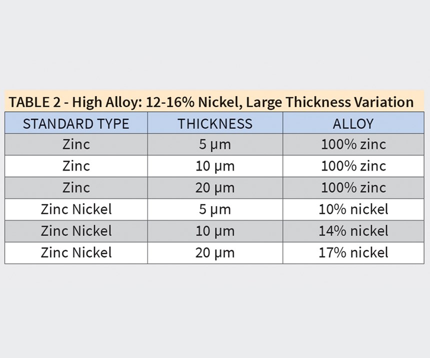
XRF Calibration Standards: It is typical for zinc nickel platers to have access to zinc XRF thickness standards. These should be used as part of the calibration set. In general, it is recommended that standards are obtained that cover the alloy range of the specification that must be met.
If you are plating high alloy, you want high alloy standards. If you are plating to meet low alloy specifications, you should have low alloy standards. A minimum of three alloy standards are recommended. Instruments should be recalibrated every four weeks. A daily alloy and thickness calibration check of one standard is also recommended. Follow the XRF supplier recommendations for recalibration frequency. The exact thickness of the zinc standards is not as critical. Use valid zinc calibration standards that are currently in use.
For customers testing low alloy, 6-12 percent nickel specifications, parts typically 5-10 μm, see Table 1.
For testing high alloy, 12-16 percent nickel with large thickness variation, see Table 2.
Hull Cell Testing: Maintaining zinc nickel alloy uniformity is critical to providing consistent corrosion protection. Checking alloy and thickness on hull cell panels, either standard hull cells or long hull cells, is required to monitor the alloy range (low vs. high alloy). Use of the long hull cell allows more detailed monitoring of alloy and thickness over a broad current density range. This is valuable for complicated parts having a large range of current densities.
Having a flat panel allows the tester to measure at the lowest measuring distance possible. It is recommended that a separate calibration be set up that makes use of this, with the measurement distance set to as low as possible, typically 0-1 cm. This will maximize accuracy in low thickness areas. Alloy measurements across the panel can be taken over time.
Some instruments allow for setting up an automated program to take measurements at specific locations, representing certain current densities. Use of this feature is recommended where possible to allow for consistent and efficient measurements.
If all the above factors are not properly considered, XRF testing data can be misleading and can provide inaccurate data regarding nickel alloys, especially in low thickness areas. Use of appropriate calibration standards for the applicable alloy specification is critical. After your XRF is optimized per the above recommendations, conduct testing with your supplier to best understand what the minimum thickness must be in order to provide accurate alloy data. This can vary significantly due to the numerous variables mentioned. Just be sure to ignore any alloy data below this minimum accuracy thickness for your machine.
Matthew is technical service director at Pavco, Inc.. Visit pavco.com.
Originally published in the July 2017 issue.
Related Content
Top Reasons to Switch to a Better Cleaning Fluid
Venesia Hurtubise from MicroCare says switching to the new modern cleaning fluids will have a positive impact on your cleaning process.
Read MoreHow to Address Declining Powder Coating Coverage Over Time
Fine particles from reclaim could be to blame for powder coating problems that emerge over time. Avoid problems by keeping hooks clean, maintaining guns and using reclaim powder quickly to avoid accumulation of fines.
Read MoreUnderstanding and Managing White Spots on Anodized Aluminum
Having trouble with spotting defects when anodizing? Taj Patel of Techevon LLC offers a helpful overview of the various causes of white spots and potential solutions.
Read MoreA Chromium Plating Overview
An overview of decorative and hard chromium electroplating processes.
Read MoreRead Next
Episode 45: An Interview with Chandler Mancuso, MacDermid Envio Solutions
Chandler Mancuso, technical director with MacDermid Envio discusses updating your wastewater treatment system and implementing materials recycling solutions to increase efficiencies, control costs and reduce environmental impact.
Read MoreA ‘Clean’ Agenda Offers Unique Presentations in Chicago
The 2024 Parts Cleaning Conference, co-located with the International Manufacturing Technology Show, includes presentations by several speakers who are new to the conference and topics that have not been covered in past editions of this event.
Read MoreDelivering Increased Benefits to Greenhouse Films
Baystar's Borstar technology is helping customers deliver better, more reliable production methods to greenhouse agriculture.
Read More


