The Behavior of Intermetallic Compounds in Aluminum during Sulfuric Acid Anodizing, Part 1: Al-Mn, Al-Fe, Al-Mg2Si, Al-Cr Alloys
The 1971 Carl E. Huessner Gold Medal Award was given to J. Cote and co-workers for the Best Paper appearing in Plating or the AES Technical Proceedings in 1970. Actually a two-part paper beginning in 1969, the first installment of the paper is republished here in a series on the AES/AESF/NASF Best Paper Awards. Their work presents very important work on how the anodizing process reacts with the other materials alloyed in with commercial aluminum grades.
by
J. Cote,1 E.E. Howlett,1 M.J. Wheeler2 and H.J. Lamb2
1Alcan Research and Development, Ltd., Kingston, Ontario, Canada
2Alcan Research and Development, Ltd., Banbury, England, U.K.
Originally published as J. Cote, et al., Plating, 56 (4), 386-394 (1969)
Editor's Note: This paper is part of a series on the AES/AESF/NASF Best Paper Awards. In 1971, J. Cote and co-workers received the Carl E. Huessner Gold Medal Award for Best Paper appearing in Plating in 1970. Although actually published in 1969, this particular article is part one of two, the second part being published in 1970. Although the deliberations of the Awards Committee are lost to history, one can infer that the award was based on the two-part package. A printable PDF version is available by clicking HERE.
ABSTRACT
The behavior of abnormally large intermetallic compounds in aluminum alloys, during anodic treatment in sulfuric acid under constant potential, was examined using an optical microscope and an electron probe microanalyzer. The intermetallic compounds were classified according to their reactivity during anodizing. In addition, point analysis by the electron probe microanalyzer was used to establish the degree to which alloying elements in the matrix are retained or dissolved during anodizing.
Introduction
The appearance and properties of anodic films on aluminum alloys are affected by the presence of intermetallic compounds resulting from impurities or deliberate additions of alloying elements. Their effect varies with their type, size, number and distribution. Because of the many and varied applications for anodic films on aluminum and the desire for improved quality, a thorough understanding is required of the behavior of these intermetallic compounds during anodizing.
Valuable work on the behavior during anodizing of several intermetallic compounds was carried out about thirty years ago by Keller and his colleagues.1,2 They grouped the alloying elements into three classifications: those that form solid solutions and have little effect on the anodic film; those that form intermetallic compounds which are either not appreciably dissolved or oxidized by the anodic oxidation treatment, or are readily dissolved or oxidized by the treatment. Fisher and his co-workers3 investigated constituents similar to those studied by Keller, et al., but they used "pure" second phase constituents and elements in addition to commercial alloys. Their work was based on phase dissolution during anodizing in sulfuric and oxalic acids. Recently, Spooner,4 by determining the chemical composition of anodic films formed in sulfuric acid on commercial aluminum alloys, has also tried to establish which alloying elements are inert, or partially or totally dissolved. Brace has also reviewed this field.5
While the above papers provide useful information, the composition and the positive identification of the intermetallic constituents were not always determined by accurate chemical analysis. These are a serious omission, as we found in our work that the presence of impurities in certain intermetallic compounds has a drastic effect upon their anodizing behavior.
Unfortunately, with the conventional metallographic examination or chemical analysis, it is difficult to establish when an intermetallic compound, after being oxidized, has remained undissolved or has been partially dissolved. In the past few years, the advent of electron probe microanalysis has provided a highly potent tool for the study of the behavior of second phase constituents during anodizing. The point analysis facilities, whereby the composition of regions or constituents as small as three microns diameter can be readily determined, and the backscatter and x-ray scanning images are particularly useful for this type of study. The actual phase compositions in or adjacent to the anodized surface can be determined while the scanning images can be used to establish the extent to which phases are attacked and the way in which component elements are distributed after anodizing. Wood and his colleagues6 were the first to report the use of electron probe microanalysis to determine the chemical composition across anodic films. Wood and Brook7 recently substantiated the original studies and extended them to the examination of the anodic behavior in sulfuric acid of a few small constituents, illustrating this behavior with back-scattered electron and x-ray scanning images. Concurrently with our work, Guminski, et al.8 carried out similar work on coatings formed anodically in oxalic acid.
In applying the electron probe microanalyzer to this field, it was considered highly desirable to re-examine the behavior of certain of the compounds which were studied in the earlier work when only optical microscopy was available. In addition, the work has been extended to compounds not previously studied.
This first article describes the sulfuric acid anodizing behavior of four intermetallic compounds, MnAl6, FeAl3, Mg2Si and CrAl7, these being representative of the different types of behavior found with sulfuric acid anodizing. The intermetallic compounds were made by slowly freezing special alloys to obtain particles of a size convenient to study their behavior. In this, as in previously published work, the optical microscope has played a major role but here it has been supported and extended by the electron probe microanalyzer.
Experimental procedure
A. Materials
The four alloys used (Table 1) were prepared by melting super-purity aluminum (Alcan 99.99%) with the appropriate high purity elements: Mn (99.99%), Fe (99.92%), Si (99.8%), Mg (99.98%), Cr (99.45%). The alloys were cast (750-800°C) in a preheated (425°C) marinite* mold of 3.9 cm (1.5 in.) diameter and 10 cm (4 in.) depth, the walls of which were 5 cm (2 in.) thick. The alloys were cooled slowly (at 1.5 to 4°C/min) to promote the formation of the large intermetallic compounds. The Al-6.4 Mg-3.7 Si alloy was investigated in both the "as cast" and homogenized (16 hr at 535°C) conditions to determine if micro-coring in the "as cast" structure could have an effect on the anodic behavior of Mg2Si.
Table 1 - Spectrographic analyses of super purity aluminum base alloys.

B. Specimen preparation and anodizing
Discs 1.9 cm (0.75 in.) thick × 3.9 cm (1.5 in.) diameter were cut from each alloy and thinned to 1.3 cm in.) thick by facing one side on a lathe. Specimens were metallographically polished as follows: emery papers (2, 1/0 and 3/0 with kerosene as the lubricant), brasso or diamond paste, and finally two-stage magnesium oxide in water using an automatic polisher.
The specimens were anodized individually at a constant potential (16V) for 30 min in sulfuric acid (15 wt%) maintained at 21 ± 1°C with moderate air agitation, followed by rinsing and drying. The anodized specimens were kept unsealed for examination. There were two reasons for using constant voltage rather than the more normal constant current density:
- Constant current density requires calculation of specimen area with the difficulties inherent in measuring this accurately in "as cast" specimens due to presence of porosity and large quantities of intermetallic compounds, and
- Because various potentials are required to oxidize different phases, it was thought more useful to anodize at constant voltage and so compare the anodizing characteristics of the various second phase constituents under equivalent conditions.
C. Metallographic and electron probe microanalysis examinations
After anodizing, a metallographic cross-section of each anodized disc was cut, coated with Bostik,** mounted in Bakelite and polished in the same way as was done before anodizing. Much information regarding the behavior of the second phase constituents was revealed by this metallographic examination.
Mating cross-sections of each specimen were prepared for microanalysis examination by mounting a small section in a hole of 6.3 mm (0.25 in.) diameter in an aluminum block of 3.2 mm (//g-in.) thickness using an electrical conducting epoxy resin FSP49.*** These blocks were mounted in Bakelite and polished in the usual way except that only diamond pastes were used in the final stages to avoid contamination by silica (from brasso) and magnesia. Specimens 6.3 mm in diameter by 3.2 mm thick as illustrated in Fig. 1 were then broken out from the composite mounts for insertion and examination in the microanalyzer.
The samples were examined in a Microscan MKII† electron probe microanalyzer. In each alloy, point analyses were obtained of the intermetallic compounds present, the matrix, the anodic film formed above the matrix, and the anodic film over the intermetallic compounds when one was present. All static measurements were made at 20 KV, except for the analysis of Mg2Si, which was carried out at 15 KV.
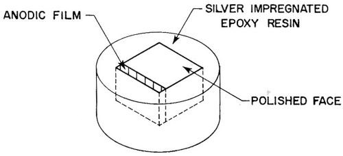
Figure 1 - Specimen for electron probe microanalysis.
Identification of intermetallic compounds was established by comparing, under the same excitation conditions, the x-ray intensities obtained for various elements with the corresponding intensities from pure standards of the elements in question. Then the chemical composition was derived, making due allowances for counting losses, background, and x-ray absorption,9 and checking the per cent values obtained with those of pure phases. In a few cases, confirmatory identifications were obtained from x-ray diffraction patterns.
For an area under study, electron backscatter and Kα radiation x-ray scanning images for the aluminum and the main alloying elements were obtained by using the scanning facilities of the microanalyzer. Optical micrographs corresponding to the scanning image were also made.
Experimental results
A. Anodic Behavior of Intermetallic Compounds
1. General
The recorded current flow during anodizing at 16V varied from one sample to another and a rough calculation of the average current density was from 1.1 to 2.1 A/dm2 (10 to 20 A/ft2) depending on the alloy. This meant that anodic film thickness varied considerably from alloy to alloy (15 to 35 microns).
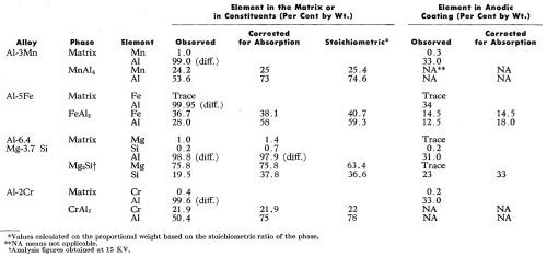
The analytical data obtained by microanalysis are summarized in Table 2. The experimentally determined compositions for the intermetallic compounds and the surrounding solid solutions have been corrected for x-ray absorption as mentioned above but the inherent difficulties in making these corrections result in the figures not summing exactly to 100%. The compositions of the anodic films have not been corrected for x-ray absorption mainly because oxygen, which has a relatively high absorption for aluminum Kα radiation, could not be measured directly. However, for the anodic films above the phases FeAl3 and Mg2Si, some adjustments have been made to compensate for the predictable effects of iron on aluminum and aluminum on silicon respectively.
The anodizing behavior of each second phase constituent is as described below.
Table 2 - Electron probe microanalyses (20 kV) of the principal elements in the matrix, the intermetallic compounds and the anodic film above each.
2. MnAl6
The only intermetallic compound present in the Al-3Mn alloy was identified as MnAl6. This was found to be neither oxidized nor dissolved to any great extent under the anodizing conditions used. Evidence of this is shown in the optical micrographs of Fig. 2 which also illustrate the variable size and shape of the intermetallic compound found in this alloy. Small particles of MnAl6 were mainly inert and were occluded in the anodic coating (Fig. 2a). Figure 2b shows a large, relatively unattacked particle. Scalloping of the anodic film around the second phase constituent is quite noticeable. It is believed that this is because the intermetallic compound thieves the current from the surrounding matrix. This results in reduced current density10 and decreased rate of oxide formation around the constituent. The small amount of aluminum oxide above the intermetallic compound (Fig. 2b) occurred because the particle was slightly below the polished surface prior to anodizing. Indeed, Fig. 3a shows another particle of MnAl6 and the corresponding electron scanning image (Fig. 3b) and the aluminum and manganese Kα radiation x-ray scanning image respectively (Fig. 3c and 3d), in which regions of high concentration appear brighter. This sequence of electron images clearly reveals that no anodic film was formed above the particle of MnAl6 at the position marked A (Fig. 3a and 3b). Therefore the MnAl6 intermetallic compound remained largely unattacked during anodizing.
The observed manganese content of the matrix was about 1 wt% while the anodic coating at Point B (Fig. 3a and 3b) contained 0.3 wt% Mn.
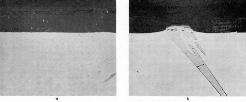
Figure 2 - Cross-section through anodized Al-3Mn alloy: (a) small MnAl6 particles (1000×); (b) large MnAl6 particle (500×).
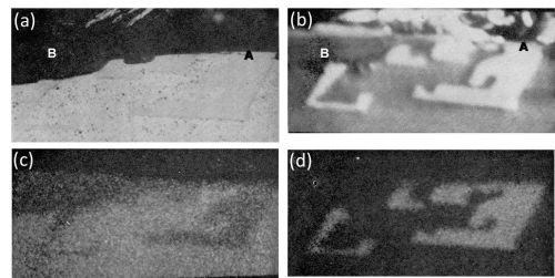
Figure 3 - Cross-section of anodized Al-3Mn alloy showing the behavior of MnAl6 (800×): (a) optical micrograph; (b) electron scanning image, (c) Al Kα radiation x-ray scanning image and (d) Mn Kα radiation x-ray scanning image.
3. FeAl3
In the Al-5Fe alloy, point analysis of the large intermetallic compounds revealed these to be crystals of FeAl3. These were the only intermetallic compounds found in the alloy. The FeAl3 constituents oxidized at approximately the same rate as the aluminum matrix resulting in a fairly smooth oxide/metal interface. This is illustrated on the optical micrograph of Fig. 4. In addition, it was also observed that with large FeAl3 intermetallic compounds, the oxide formed was thicker than that above the aluminum matrix (Fig. 4). The greater thickness of the anodized FeAl3 appeared to result from a greater volume expansion of the anodized FeAl3 than the aluminum matrix. Assuming a possible reaction of 2FeAl3 ⇒ Fe2O3 + 3Al2O3, crude calculation based on apparent density of each compound indicated a volume ratio of 1.5 to 2.0 for

The oxide /metal ratio of the corrected values (Table 2) for the iron (14.5:38.1 = 0.38) and of the aluminum (18:58 = 0.31) of the anodized FeAl3 phase were similar, indicating that the iron was effectively retained in the anodic film above the FeAl3 phase. Another interesting fact to note is that the ratio of iron to aluminum in the oxide portion of the intermetallic compound (14.5:18 = 0.81) was approximately equal to the same ratio in FeAl3 (40:60 = 0.67).

Figure 4 - Cross-section of anodized Al-5Fe alloy showing anodized FeAl3 (500×).
The electron scanning image and the aluminum and iron Kα radiation x-ray scanning images, of another particle of FeAl3 are shown in Fig. 5. The iron image clearly shows the distribution of iron in the anodic film and indicates that the FeAl3 crystal was attacked during the anodizing process and that the iron remained more or less in situ in the anodic film.
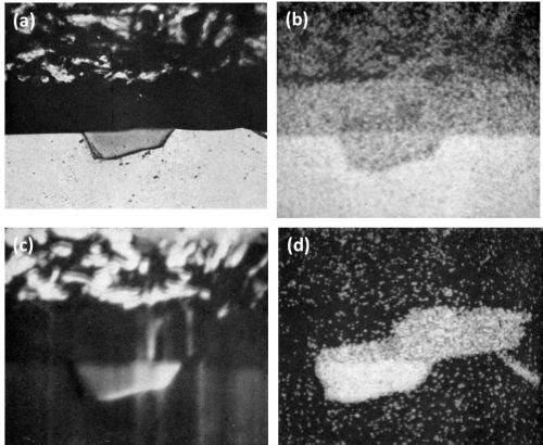
Figure 5 - Cross-section of anodized Al-5Fe alloy showing the behavior of FeAl3 (600×): (a) optical micrograph; (b) electron scanning image; (c) Al Kα radiation x-ray scanning image and (d) Fe Kα radiation x-ray scanning image.
4. Mg2Si
In the as cast structure of the Al-6.4 Mg-3.7 Si Alloy, the primary crystals were identified as Mg2Si along with fine needles of Mg2Si precipitate in addition to rosettes of eutectic silicon. In the homogenized structure, only primary crystals of Mg2Si were present. No difference was found in the behavior of Mg2Si, either in the as-cast or homogenized structure. The anodic oxidation of Mg2Si took place at a faster rate than that of the matrix with partial dissolution leaving a cavity in the anodic coating as illustrated in Fig. 6. Scalloping of the anodic film occurred with both the as cast and homogenized structure due to current "thieving." This was not due to micro-coring as might be expected with as cast material,11 since the homogenized structure produced the same phenomenon. The point analysis of the oxide above the Mg2Si particles, in the homogenized sample, indicated only traces of magnesium while the unattacked particles contained about 64 wt%. On the other hand, only slight reduction in silicon content was noted between the attacked and unattacked portion of particles of Mg2Si. This indicated that during anodizing magnesium in the Mg2Si is dissolved away while silicon is not appreciably dissolved.
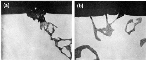
Figure 6 - Cross-section of anodized Al-6.4 Mg-3.7 Si alloy illustrating the behavior of Mg2Si (500×): (a) as cast structure and (b) in homogenized condition.
The dissolution of magnesium is well illustrated in the various scanning images in Fig. 7. Figure 7c clearly reveals that all the magnesium was dissolved while silicon (Fig. 7d) was retained in the anodic film. It was interesting to observe that although the matrix contained approximately 1.0 wt% magnesium and 0.2 wt% silicon, analysis of the anodic coating above the matrix revealed only traces of magnesium and no appreciable dissolution of the silicon.
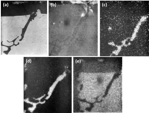
Figure 7 - Cross-section of anodized Al-6.4 Mg-3.7 Si showing the behavior of Mg2Si (500 ×): (a) optical micrograph; (b) electron scanning image; (c) Mg Kα radiation x-ray scanning image; (d) Si Kα radiation x-ray scanning image and (e) Al Kα radiation x-ray scanning image.
5. CrAl7
The microstructure of the Al-2Cr alloy consisted of needles and plate-like intermetallic compounds, identified by point analysis as CrAl7 embedded in a matrix containing 0.4 wt% chromium as measured by probe analysis. As expected,12 a deep gold anodic film was obtained with this aluminum-chromium alloy. The particles of CrAl7 were anodized or dissolved at a much faster rate than the aluminum matrix as illustrated in Figs. 8a and 8b. The cross-sections revealed that the constituents were preferentially attacked during anodizing and rapidly dissolved (leached out). The electrolyte then penetrated into the cavity remaining and anodized the aluminum matrix surrounding the dissolved constituents. The particle in Fig. 8a was completely dissolved and the surrounding aluminum was oxidized (progressively sideways) as shown by the gap between the oxide layers forming the cavity wall and the surface oxide. The dissolution of the intermetallic compound was apparent from the hole in the coating, while the break in the oxide between the top surface and that along the oxidized cavity wall of the dissolved constituent proved that oxide growth occurred from different directions.
Figure 8b shows a remnant of a large particle of CrAl7 which had not yet been attacked. The rest of the particle was dissolved and the cavity walls oxidized. Since there is no apparent void in the anodic film above the dissolved particle, this suggests that part of the CrAl7 crystal extended, before anodizing, to the metal surface in another plane some distance away from the selected area shown in Fig. 8b.
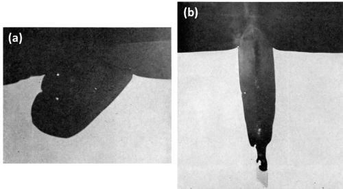
Figure 8 - Cross-section of anodized Al-2Cr alloy showing the behavior of CrAl7 (1000×): (a) completely dissolved and (b) almost completely dissolved.
The electron scanning image and the aluminum and chromium Kα radiation x-ray scanning image from another region, shown in Fig. 9a, are illustrated respectively in Figs. 9b to 9d. Figure 9d shows that little or no chromium was retained in the anodic film in the region where preferential attack has taken place. In fact, no significant difference could be detected in the composition of the anodic film between areas A and B (Fig. 9a and 9b), since point analysis of both regions gave the observed analysis of 33 wt% aluminum and 0.2 wt% chromium. This was a further indication that the anodic coating along the cavity walls was formed from the matrix after the particle of CrAl7 had been dissolved. The Kα radiation for chromium in Fig. 9d reveals a rather sharp reduction in concentration between the remnant CrAl7 and the dissolved region. This suggests that virtually no oxide coating was formed on top of the CrAl7 particle and thus it appears that this phase was rapidly dissolved without formation of an oxide film or as soon as an oxide film was formed.
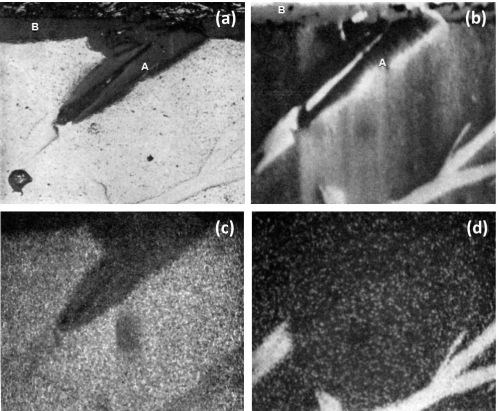
Figure 9 - Cross-section of anodized Al-Cr alloy showing the behavior of CrAl7 (450×): (a) optical micrograph, (b) electron scanning image, (c) Al Kα radiation x-ray scanning image, (d) Cr Kα radiation x-ray scanning image.
B. Retention of solute elements in anodic films
Even with some limitation in the accuracy of the electron probe microanalyzer (±5%), the analysis figures are considered sufficiently accurate to determine whether elements in solid solution were retained or dissolved during anodic oxidation.
The distribution of the alloying elements in the matrix and in the anodic coating, and of the aluminum content in the anodic films, are shown in Table 2. The observed aluminum content in the anodic film was between 31-34 wt% giving an aluminum in oxide/metal composition ratio of about 0.3. These figures are in good agreement with those found by Wood, et al.6 The uncorrected aluminum content of the oxide film was somewhat low when compared with the figures of 37.3-43.3% from chemical analysis, found by Kape,13 with a calculated value of 46% as used by Spooner4 and with a corrected value of about 50% found by Wood and his colleagues7,14 by electron probe microanalysis. In this work, an oxide/metal composition ratio of 0.3 was used as the base for comparison of the action of various elements. A ratio of less than 0.3 suggested that the alloying elements in solid solution were dissolved during anodizing relative to aluminum while values equal to or higher than 0.3 suggested that the elements were retained relative to aluminum in the anodic film. From the observed electron microprobe analyses (Table 2), the oxide/metal composition ratios of the alloying elements in solid solution are listed in Table 3 along with their degree of "solubility" of the elements or of their oxidation products during the anodizing process. The degrees of solubility in brackets are those obtained by Spooner4 using quantometric and x-ray emission spectroscopic analyses of both the metal and gross oxide coating of sulfuric anodic films produced on commercial alloys.
Table 3 - Solubility of solute elements during sulfuric acid anodizing of aluminum alloys.
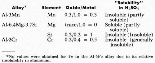
The above results agree rather well with Spooner's results although his technique does not differentiate between the elements that were present in solid solution or as intermetallic compounds. In addition, some different results might be expected if the exact analyses rather than the observed electron probe analyses were available.
It is interesting to note that in an Al-Mg-Si alloy, magnesium is dissolved, while silicon is retained, similar to the behavior of Mg2Si. On the other hand, chromium in solid solution was retained, while CrAl7 was readily dissolved during anodizing. This confirms that it is the chromium in solid solution rather than chromium-aluminide precipitates which produces the gold color on Al-Cr alloys during sulfuric acid anodizing.
Discussion
The present experimental results on the behavior of intermetallic compounds during sulfuric acid anodic oxidation are in partial agreement with similar studies by Keller, et al.1,2 Concerning the four phases reported in this paper, we are in agreement that the following occurs during anodizing:
- MnAl6 is relatively inert and is carried into the coating.
- FeAl3 oxidizes at approximately the same rate as the aluminum matrix and oxidation products are retained in the film.
- Mg2Si oxidizes more rapidly than the aluminum matrix.
Our results on CrAl7 disagree with those reported by Keller and indicate that this phase oxidizes or dissolves at a much faster rate than the matrix, while Keller observed that this intermetallic compound was not oxidized or dissolved as rapidly as the aluminum matrix.
This discrepancy could be explained either by differences in anodizing conditions or possibly by differences in the aluminum matrix due to varying alloy composition and casting practices. Keller, in his work, used constant current density with the voltage probably varying appreciably in some cases, while we used constant voltage with current density varying very appreciably with the various alloy systems. Current density could not be measured because calculation of the true surface area of a porous casting was impractical.
Wood and Brock7 have reported that FeAl3 constituents were inert during sulfuric acid anodizing where a current density of 2.7 A/dm2 (25 A/ft2) was used which required 19.1 to 19.8 volts. This material was sheet and the constituents were relatively small. It is possible that, during anodizing, because of their small size, most of the constituents were electrically cut off by the oxidation process so that the FeAl3 particles could not be entirely oxidized and thus were carried into the anodic film as inert particles.
The intermetallic compounds which oxidize at approximately the same rate as the matrix with no apparent dissolution of the oxide formed, produce a fairly smooth oxide / metal interface and should be without adverse effects on the image clarity of bright-anodized material. On the other hand, intermetallic compounds which are inert or which oxidize at about the same or at a faster rate than the matrix but in which the oxide formed is more or less dissolved, produce a rather rough air/oxide or oxide/metal interface. Where the oxide intermetallic compounds are dissolved, holes or voids are left in the anodic film. Both effects - roughening at the oxide / metal interface and dissolution of oxidized intermetallic compounds - are detrimental to the brightness, appearance, and corrosion resistance of the anodic films.
Conclusions
The electron probe microanalyzer complements the light microscope and provides a powerful tool in studying the anodizing behavior of intermetallic compounds. It provides not only chemical analysis at various points as the material is scanned but with Kα radiation yields an x-ray scanning image of aluminum or of individual alloying elements; these two techniques can be used to clearly show the reaction during anodic treatment of intermetallic compounds and of elements in solid solution, particularly the extent and manner in which these are carried into the anodic film. The noted behavior of MnAl6 (inert), FeAl6 (the same rate as the matrix) and Mg2Si (more rapidly than the matrix with some dissolution) was in agreement with that previously reported2,3 but CrAl7 was readily oxidized and dissolved rather than being inert. Manganese, silicon and chromium in solid solution are retained in the anodic film while magnesium is dissolved.
References
1. F. Keller and G.W. Wilcox, Metals and Alloys, 10 (6), 187 (1939).
2. F. Keller, G.W. Wilcox, M. Tosterud and C.D. Slunder, ibid., 10 (7), 219 (1939).
3. M. Fisher, M. Budiloff and L. Kock, Korrosion u. Metallschutz, 16 (718), 236 (1940).
4. R.C. Spooner, Plating, 53, 451 (1966).
5. A.W. Brace, Metallurgia, 55 (330), 173 (1957).
6. G.C. Wood, V.J.J. Marron and B.W. Lambert, Nature, 199, 239 (1963).
7. G.C. Wood and A.J. Brock, Trans. Inst. Metal Finishing, 44, 189 (1966).
8. R.D. Guminski, P.G. Sheasby and H.J. Lamb, Trans. Inst. Metal Finishing, 46, 44 (1968).
9. R. Castaing, Advances in Electronics and Electron Physics, Academic Press, New York and London, 1960, Vol. XIII; p. 317.
10. W.E. Cooke, Plating, 49, 1157 (1962).
11. J. Herenguel and P. LeLong, Metal Finishing J., 4 (1), 20 (1958).
12. M.C. Fetzer, P.R. Sperry and J.F. Murphy, US Patent 3,107,159 (1957).
13. J.M. Kape, Metal Ind., 91, 63 (1957).
14. G.C. Wood and V.J.J. Marron, Trans. Inst. Metal Finishing, 45, 107 (1967).
About the authors


Footnotes
*An insulating product made of amosite asbestos fiber, diatomaceous silica and an inorganic binder: Johns-Manville Co.
**A proprietary adhesive composed of synthetic resins in alcohol; B.B. Chemical Co. of Canada, Ltd., Montréal, Québec, Canada.
***Johnson, Matthey and Co., Ltd.
†Cambridge Instrument Company.
Related Content
AESF Heritage: SUR/FIN 2000 – European Academy of Surface Technology: Copper Microelectrodeposition: The Influence of Different Additives on Growth in Microprofiles
In this work, a pH 3.0, 0.8M copper sulfate electrolyte was used for plating onto both blanket and patterned silicon wafers. This novel electrolyte, proposed by U. Landau, involves a number of beneficial effects with respect to the conventional bath.
Read MoreCalculating Applied Media Force During Vibratory Finishing
What appear to be identically set-up vibratory bowls will finish identical loads of parts in varying time cycles. This paper offers a new technique to better predict what the operator will produce, by measuring the force applied to the parts. It is the efficiency of that force which controls the efficiency and speed of the refinement cycle.
Read MoreMaterial Database Enables Coating Thickness Measurement Without Calibration
The database from Coatmaster AG has calibrations of over 400 different RAL colors.
Read MoreRead Next
Education Bringing Cleaning to Machining
Debuting new speakers and cleaning technology content during this half-day workshop co-located with IMTS 2024.
Read MoreDelivering Increased Benefits to Greenhouse Films
Baystar's Borstar technology is helping customers deliver better, more reliable production methods to greenhouse agriculture.
Read MoreA ‘Clean’ Agenda Offers Unique Presentations in Chicago
The 2024 Parts Cleaning Conference, co-located with the International Manufacturing Technology Show, includes presentations by several speakers who are new to the conference and topics that have not been covered in past editions of this event.
Read More


.jpg;maxWidth=300;quality=90)

