The Behavior of Intermetallic Compounds in Aluminum during Sulfuric Acid Anodizing Part 2: Al-Cu, Al-Mg, Al-Si, Al-Ti, Al-Fe-Si, Al-Zn-Mg Alloys
The 1971 Carl E. Huessner Gold Medal Award was given to J. Cote and co-workers for the Best Paper appearing in Plating or the AES Technical Proceedings in 1970. Actually a two-part paper beginning in 1969, the second installment of the paper from 1970 is republished here in a series on the AES/AESF/NASF Best Paper Awards. Their work presents very important work on how the anodizing process reacts with the other materials alloyed in with commercial aluminum grades.
by
J. Cote,1 E.E. Howlett1 and H.J. Lamb2
1Alcan Research and Development, Ltd., Kingston, Ontario, Canada
2Alcan Research and Development, Ltd., Banbury, England, U.K.
Originally published as J. Cote, et al., Plating, 57 (5), 484-496 (1970)
Editor's Note: This paper is part of a series on the AES/AESF/NASF Best Paper Awards. In 1971, J. Cote and co-workers received the Carl E. Huessner Gold Medal Award for Best Paper appearing in Plating in 1970. This particular article is part two of two, the second part having been published in 1969. Although the deliberations of the Awards Committee are lost to history, one can infer that the award was based on the two-part package. A printable PDF version is available by clicking HERE.
ABSTRACT
The behavior of coarse particles of five intermetallic compounds, CuAl2, beta AlMg, Si,* TiAl3, beta AlFeSi and the T (AlZnMg) phase** in high purity based aluminum alloys, during sulfuric acid anodizing under constant d-c potential, has been examined using optical microscopy and electron probe microanalysis. Point analysis was used to identify the constituents and to measure compositions within the matrices and the anodic films while the ultra-slow scan technique was used to determine concentration profiles through the anodic films. Results are compared with those of other workers in this field. As expected, Si was inert as were TiAl3 and beta AlFeSi while CuAl2, beta AlMg, and the T (AlZnMg) phase were anodized faster than the matrix and readily dissolved in the electrolyte. Of the elements in solid solution, silicon was retained in the anodic film, zinc was partly soluble, while copper, iron, and magnesium dissolved in the electrolyte.
Introduction
In an earlier paper,1 we described the anodic behavior in sulfuric acid, under constant d-c potential, of a few large intermetallic compounds (MnAl6, FeAl3, Mg2Si and CrAl7) in high purity base aluminum alloys. These intermetallic compounds were respectively inert, anodized at the same rate, anodized faster, and readily dissolved in the electrolyte with respect to the matrix during the anodizing process. The anodic behavior of the intermetallic compounds was studied by making extensive use of an electron probe microanalyzer and its scanning backscatter electron and x-ray imaging systems. This tool proved very useful for the identification of intermetallic compounds (confirmed by x-ray diffraction technique) and for the quantitative analysis of intermetallic compounds, matrices and anodic films formed above them. Thus the concentration of the major alloying elements could be determined and, even with an accuracy of ± 5%, it was possible to establish whether or not the elements were retained in the anodic films.
The object of the present work is to describe the anodic behavior of another group of intermetallic compounds. The constituents were selected because of their common occurrence in various commercial aluminum alloys and because these constituents, through their anodizing characteristics, can influence the appearance and corrosion resistance of anodized products. The intermetallic compounds examined were CuAl2, beta AlMg, Si, TiAl3, beta AlFeSi and the T (AlZnMg) phase. Although the anodic behavior of these intermetallic compounds in either sulfuric acid or oxalic acid electrolytes has been reported by various workers,2-8 further evidence was obtained which confirms or questions what has been previously found.
The behavior of alloying elements in solid solution in the aluminum matrix is of importance since this may affect, to some degree, the properties of anodic films. In some instances, a different anodizing response was observed depending upon whether the elements were in solid solution or formed intermetallic compounds.1 Using a technique similar to that of Wood and Brock,8 the distribution of alloying elements across matrix-anodic film was measured by the slow-scan of an electron probe microanalyzer. The behavior of elements in solid solution was then compared with other work where such behavior was determined by the x-ray fluorescence method.9,10
Experimental
The eight alloys investigated (Table 1) were prepared, as in our earlier work,1 by melting super-purity aluminum (Alcan 99.99%) with the appropriate addition of commercially high purity elements: Cu (99.96%), Si (99.8%), Ti (99.99%), Mg (99.98%), Fe (99.92%), Zn (99.99%). Some of the alloys were cast (Table 1) in a preheated marinite mold, as used previously, so providing a slow cooling rate (1.5 to 4°C/min). However, in other cases, a medium cooling rate (20 to 30°C/min) was necessary because of (1) the too great solubility of alloying element in the matrix which prevented the formation of sufficiently large intermetallic compounds under slow cooling conditions or (2) to minimize peritectic reaction around intermetallic compounds. This was accomplished by using a preheated (400°C) steel mold designed to produce tapered round bar of 2.5 to 3.8 cm by 17.8 cm long (1 to 1.5 in. by 7 in.). The mold was coated with Mica Wash*** to give more uniform cooling conditions.
Table 1 - Casting conditions and spectrographic analyses of super-purity aluminum base alloys.

The Al-13Si alloy was investigated in both the as-cast and homogenized (16 hr at 555°C) conditions.
The specimen preparation, anodizing conditions in sulfuric acid electrolyte (15 wt%, 21°C) under constant d-c potential (16V), and procedures for metallographic and electron probe microanalysis examination were similar to those outlined previously.1 In addition, in a few cases, the profile distribution of aluminum and the alloying elements through the anodic films formed above the matrix was carried out by using the ultra-slow scanning device of the electron probe microanalyzer.8 All measurements were made at 20 KV.
Experimental results
A. Anodic behavior of intermetallic compounds
1. General
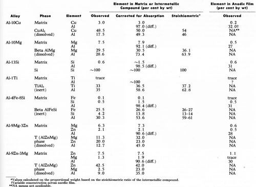
During the 30 min period of anodizing under constant potential, current flow for the individual specimen was recorded. The current varied from sample to sample but, as expected11,12 was higher with aluminum-magnesium and aluminum-zinc-magnesium alloys with an apparent current density of about 3.2 A/dm2 (30 A/ft2) resulting in an anodic film 100 to 125 microns thick. The current flow on the other alloys was lower, being about 1.1 to 1.6 A/dm2 (10-15 A/ft2), which produces anodic film thicknesses of 6 to 25 microns depending on the alloy. With the Al-10% Cu alloy, a very thin film was formed owing probably to a lower current density6 attributed, among other things, to increased ohmic resistance of the anodic film due to the presence of copper11 (or copper oxides) and the lower anode current efficiency.12 The analytical data obtained by electron probe microanalysis are summarized in Table 2. Wherever possible, the observed values have been corrected for x-ray absorption. For reasons explained elsewhere,1 the corrected values did not add up to 100%. The elemental compositions of the anodic films of those particles which oxidized, and of the various aluminum matrices are also included in Table 2. In this case, no attempt to correct the composition in the anodic film for absorption effect was made because of inherent difficulties in measuring the oxygen content in the anodic films. However, the observed aluminum content of anodic films was within the range obtained by Wood, et al.13 who used similar techniques.
Table 2 - Electron probe microanalyses (20 kV) of the major alloying elements in the matrix, the intermetallic compounds and the anodic film above each.
The anodic behavior of each intermetallic compound is as described below.
2. CuAl2
The slow cooled Al-10Cu alloy contained a mixture of primary crystals identified as CuAl2 in addition to eutectic regions of CuAl2-aluminum. Point analysis of CuAl2, both as primary and eutectic particles contained, after correction, 50 wt% Cu (Table 2).
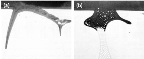
Figure 1 - Cross-section through anodized Al-10Cu alloy: (a) primary crystal of CuAl2 (400×) and (b) eutectic CuAl2-aluminum (500×).
The anodic behavior of both primary and eutectic CuAl2 is well illustrated in Fig. 1. The formation of a thin anodic film with this alloy can also be noted. Primary crystals of CuAl2 (Fig. la) were rapidly oxidized and readily dissolved in the electrolyte and the cavity walls of the gradually dissolving particles were progressively oxidized. Anodizing of the CuAl2-aluminum eutectic (Fig. lb) also resulted in the rapid oxidation-dissolution of the CuAl2 component although the aluminum component was also oxidized, but some segments of aluminum were electrically cut off from the eutectic network before they had been completely oxidized. In this manner, aluminum particles were retained in the oxide coating as are inert particles. The dissolution of the oxidized CuAl2 particles resulted in production of small fresh areas which in turn are anodized and through which most of the current will flow. In all likelihood, the current density over the oxidized surface is therefore reduced. This effect might also have contributed in the formation of a thin anodic film with this alloy composition.
The optical micrograph, the corresponding electron scanning image, and the aluminum and copper Kα radiation x-ray scanning images for another particle of primary CuAl2 are shown in Fig. 2. The oxidation of the cavity walls can be clearly noted in the aluminum Kα radiation image (Fig. 2c). The oxidation of the intermetallic particles can be noted in Fig. 2d; this shows the copper concentration at the tip of the dissolving branches to be less than that in the bulk of the particle.
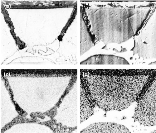
Figure 2 - Cross-section of anodized Al-10Cu alloy showing the behavior of primary CuAl2 (Original magnification 500×): (a) optical micrograph, (b) electron scanning image, (c) Al Kα radiation x-ray scanning image and (d) Cu Kα radiation x-ray scanning image.
3. Beta AlMg
The slow cooled Al-10Mg alloy contained large irregularly shaped intermetallic particles identified as beta AlMg which is sometimes referred to as Mg5Al8 or Mg2Al3. Point analysis revealed that beta AlMg had a corrected value of 30.5 wt% magnesium while the matrix contained 7.9% magnesium (Table 2). As expected, in the metallographically as-polished condition, beta AlMg was hardly distinguishable14 from the aluminum matrix (Fig. 3).
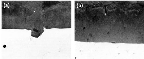
Figure 3 - Cross-section through anodized Al-10Mg alloy: (a) large beta AlMg crystals, slow-cooled (Original magnification 300×) and (b) small beta AlMg particles, medium-cooled (Original magnification 500×).
The beta AlMg constituents anodized at a slightly faster rate than the aluminum matrix and dissolved in the electrolyte, producing large discontinuities or voids in the anodic coating (Fig. 3a)(In these cases, the voids became filled with "Bostik" mounting lacquer.). Some scalloping of the metal/oxide interface near the crystal of beta AlMg has occurred and this is attributed to the current thieving.15
A similar alloy, cast under medium-cooling conditions, resulted in the formation of small spheroidal constituents also identified as beta AlMg. These were also anodized and dissolved during anodizing leaving holes in the anodic coating (Fig. 3b).
With both samples pronounced roughness resulted at the electrolyte/oxide interface as compared to a relatively smooth oxide/metal interface especially noticeable in Fig. 3b. The dissolution of the oxidized constituents appeared to be partly responsible for the formation of the irregular oxide/electrolyte interface.
The dissolution of beta AlMg compounds is confirmed by the Kα radiation x-ray scanning images (Fig. 4) of a beta AlMg particle. Here, the intermetallic particle is of similar mean atomic number to that of the matrix and hence is faintly visible on the electron image (Fig. 4b). Figures 4c and 4d show more clearly that the discontinuity in the anodic film is, in fact, a hole and that it appears that the beta AlMg compounds dissolved as fast as they were anodically oxidized.
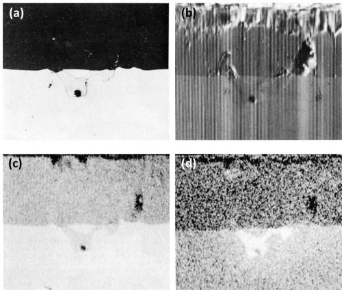
Figure 4 - Cross-section of anodized Al-10Mg alloy showing the behavior of beta AlMg (300×): (a) optical micrograph, (b) electron scanning image, (c) Al Kα radiation x-ray scanning image and (d) Mg Kα radiation x-ray scanning image.
4. Si
The slow cooled Al-13Si alloy contained only eutectic silicon of which point analyses gave, within the experimental error, 100 wt% silicon. Some microcoring, i.e., variation of the silicon content in the aluminum matrix, in the vicinity of silicon particles, was noted in the as-cast sample. However, at some distance away from the silicon particles, point analysis of the matrix revealed a corrected concentration of approximately 1.5 wt% silicon (Table 2). Point analysis of the matrix on the homogenized sample showed similar silicon content suggesting that microcoring in the as-cast sample was only light.
Optical micrographs of cross sections of anodized samples in the as-cast and in the homogenized conditions are shown in Figs. 5a and 5b respectively. As expected, no attack of the silicon particles occurred and they protruded into the anodic film. Due to the inert nature of the silicon particles, a very irregular film resulted both at the electrolyte/oxide and oxide/metal interface.
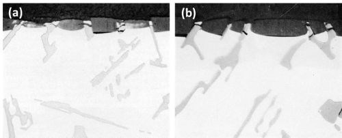
Figure 5 - Cross-section of anodized Al-13Si (500×): (a) as cast and (b) homogenized (16 hr at 555°C).
The pronounced scalloping of the anodic film around the silicon particles occurred in both the as-cast and homogenized samples and was therefore not caused by coring. However, this effect, as mentioned in our earlier paper,1 can be caused either by current thieving from the intermetallic compounds15 or possibly, because of their apparent high electrical resistance, by the intermetallic particles acting as shields to the current flow. Figures 5a and 5b show a strong dependence of the scalloping of the anodic film with orientation of the silicon particles suggesting that current shielding rather than current thieving had taken place. Break-up of the silicon particles is also apparent, and this is almost certainly due to the silicon particles fracturing under the stresses developed by the expansion of the oxide film relative to the metal from which it has formed. It is possible, but considered very unlikely, that the break-up occurred during metallographic preparation.
The inertness of the Si constituents is quite evident from the series of the electron and aluminum and silicon Kα radiation x-ray scanning images, (Fig. 6), on another area of the Al-13Si alloy.
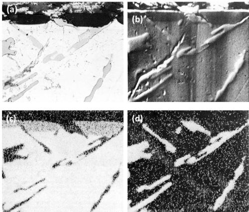
Figure 6 - Cross-section of anodized Al-13Si alloy illustrating the behavior of eutectic silicon (Original magnification 500×): (a) optical micrograph, (b) electron scanning image, (c) Al Kα radiation x-ray scanning image and (d) Si Kα radiation x-ray scanning image.
5. TiAl3
The needle-shaped intermetallic particles present in the medium cooled Al-1 Ti alloy were identified as TiAl3. (This alloy was also prepared under slow cooling conditions but no intermetallic compounds could be detected.†) No titanium was detected in the aluminum matrix and none in the anodic film.
During anodizing, the TiAl3 particles seemed inert and were projected into the anodic film (Fig. 7) with "scalloping" of the anodic film taking place, around the particle, at the oxide/metal interface. Fracture of the needle-shaped TiAl3 particle occurred in the anodic film, in the same manner as with silicon particles and presumably for the same reason. In Fig. 7, aluminum trapped between pieces of TiAl3 remained unoxidized owing to electrical cut-off. This strongly suggests that fracture of the inert intermetallic compounds occurred during anodizing rather than during metallographic polishing. Further evidence of the inert behavior of the TiAl3 particles is illustrated in the series of electron probe x-ray images (Fig. 8). Here it appeared that some thinning of the TiAl3 needles could have taken place. This apparent thinning can be noted particularly on the left hand particle of TiAl3 (Fig. 8d) but two slow scans across this particle, first where it projects into the film, and second where it is still embedded in the matrix, failed to reveal any titanium in the anodic film adjacent to the needle. This seems to indicate that if some slight dissolution of the TiAl3 particles has occurred, the titanium was not retained in the film.
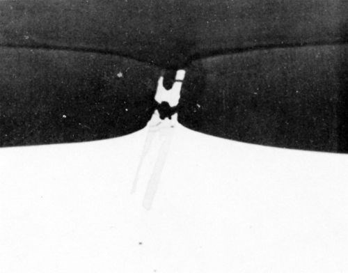
Figure 7 - Cross-section through anodized Al-1 Ti alloy (1000×).
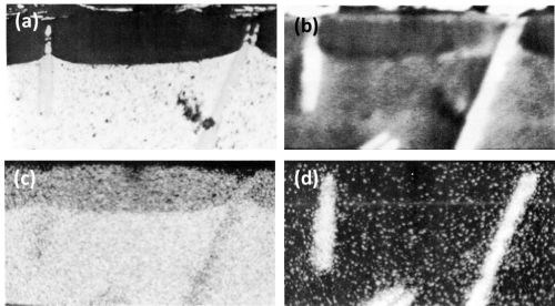
Figure 8 - Cross-section of anodized Al-1 Ti alloy illustrating the behavior of TiAl3 (750×): (a) optical micrograph, (b) electron scanning image, (c) Al Kα radiation x-ray scanning image and (d) Ti Kα radiation x-ray scanning image.
6. Beta AlFeSi
The Al-4Fe-8Si alloy was examined in both slow and medium cooled conditions. In the slowly solidified sample, large plates and small needles of beta AlFeSi were identified along with angular particles of eutectic silicon (Fig. 9a). In the medium cooled sample, small needle-shaped beta AlFeSi particles were present but there was little evidence of eutectic silicon (Fig. 9b). The observed point analysis of the beta AlFeSi compound gave the result (Table 2) of 25.5 wt% iron, 4.2 wt% silicon and 30.3 wt% aluminum. Correcting these figures according to Birks16 gives 26.6 wt% iron, 13.8 wt% silicon and 53.6 wt% aluminum. However, experience with microanalysis of iron-aluminum intermetallic compound in this composition range indicates that the corrected iron figures are usually about 1 wt% low compared with the figures given by chemical analysis of the extracted crystals. Therefore, the exact iron content should be in the vicinity of 27.6 wt% iron. Based on the aluminum content, the Fe:Al ratio is roughly 1:2 and Si:Al is 1:4. In both samples, the corrected analysis matrix showed 0.1 wt% iron and 1.5 wt% silicon.
The beta AlFeSi particles were inert to anodic oxidation under the anodizing conditions used (Fig. 9). With the small needle-shaped particles (Fig. 9b), the portion protruding in the anodic film was broken-up. The "scalloping" of the anodic film around the inert particles occurred as with the other above inert intermetallic compounds. In Fig. 9a, a small particle of eutectic silicon was present (upper left) and as expected this was inert.
The series of optical and the corresponding electron scanning images and the aluminum, iron and silicon Kα radiation x-ray scanning images of another particle of beta AlFeSi are illustrated in Fig. 10. There was no indication that any kind of attack took place. The beta AlFeSi particle was totally inert.
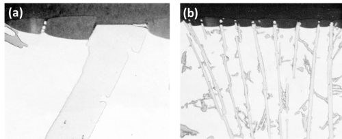
Figure 9 - Cross-section of anodized Al-4Fe-8Si alloy (500×): (a) large beta AlFeSi and eutectic silicon (upper left), (b) needles of beta AlFeSi, medium-cooled.
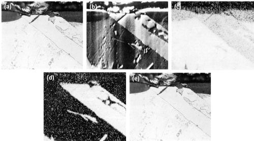
Figure 10 - Cross-section of anodized Al-4Fe-8Si alloy illustrating the behavior of AlFeSi (500×): (a) optical micrograph, (b) electron scanning image, (c) Al Kα radiation x-ray scanning image, (d) Fe Kα radiation x-ray scanning image and (e) Si Kα radiation x-ray scanning image.
7. T (AlZnMg) phase
The only intermetallic compounds found in either of the slow-cooled Al-Zn-Mg alloys were identified as the T phase. In the Al-9Mg-3Zn alloy, irregularly-shaped crystals of the T phase were present (Fig. 11a), containing, after corrected electron probe microanalysis (Table 2), 32 wt% magnesium, 23 wt% zinc and 45 wt% aluminum. The corrected matrix analysis revealed 7.3 wt% magnesium and 2.1 wt% zinc. In the Al-9Zn-3Mg alloy, the only intermetallic compounds observed occurred in regions of eutectic mixture (Fig. 11b) of aluminum and T phase. Point analysis (Table 2) of this T phase showed corrected values of 42.0 wt% zinc, 23.0 wt% magnesium and 35.0 wt% aluminum associating the T phase to (Al,Zn)49Mg32. In this case the corrected matrix analysis shows 7.5 wt% zinc and 1.9 wt% magnesium. The composition of the T phase was therefore different in the two alloys, confirming that this phase has a wide range of composition.14 With the alloy composition and casting conditions used, no formation of a magnesium-zinc intermetallic compound (such as MgZn2) was observed.
The T phase in both alloys was found to oxidize at a slightly faster rate than the matrix and the oxidation product was rapidly dissolved in the electrolyte during the anodizing process (Fig. 11) leaving voids in the anodic films. The small white particles entrapped in the anodic film (Fig. 11b) were unoxidized or only partly oxidized aluminum from the aluminum T phase eutectic regions from which the T phase was oxidized and dissolved resulting in electrical cut-off of the aluminum eutectic component.
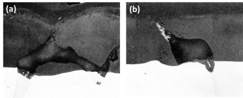
Figure 11 - Cross-section of anodized Al-Mg-Zn alloys (Original magnification 400×): (a) Al-9Mg-3Zn showing large particle of T phase and (b) Al-9Zn-3Mg showing eutectic of Al-T phase.
Clearer evidence of the rapid dissolution of the oxidized T phase is shown in the series of optical-electron x-ray scanning images (Fig. 12) of an intermetallic particle in the Al-9Mg-3Zn alloy. The slightly faster anodizing rate, of the T phase particles in regards to the matrix, is shown in the electron scanning image (Fig. 12b). The complete dissolution in the electrolyte of the particle in the anodic film is well shown in Figs. 12c and 12d. Figure 12d shows an apparent enrichment of magnesium at the outer edges of the anodic film. This was due to contamination with magnesia, which had to be used in the final stage of preparation in order to show up the particles without actually etching the specimen.
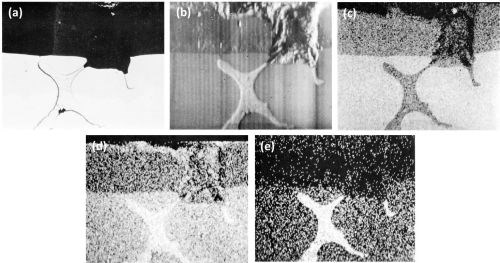
Figure 12 - Cross-section of anodized Al-9Mg-3Zn alloy illustrating the behavior of T (AlZnMg) phase (Original; magnification 300×): (a) optical micrograph, (b) electron scanning image, (c) Al Kα radiation x-ray scanning image, (d) Mg Kα radiation x-ray scanning image and (e) Zn Kα radiation x-ray scanning image.
B. Retention of solute elements in anodic films
By using slowly solidified material, regions free of intermetallic compounds could be selected where the distribution of the alloying elements, in solid solution, through the matrix and the anodic film was determined without possible interference from the intermetallic particles.
The observed static probe analysis data for the elements in the matrix and in the anodic films, for the various alloys, are listed in Table 2 along with the corrected values for the elements in the matrix. In order to obtain some indication of the concentration profile of elements in the anodic films, analysis by the ultra-slow scanning facilities of the instrument was made but only of the single element alloy addition, such as the Al-10Cu, Al-10Mg and Al-13Si alloys.†† As revealed by the concentration profile distribution curves, described below, the concentration of alloying element across anodic films varied somewhat, i.e., decreasing from the oxide/metal through the oxide/electrolyte interfaces. Therefore, the static measurements of the observed concentrations in Table 2 are not truly average concentrations. They represent values rather nearer the oxide/electrolyte interface, where more porous film existed than the oxide/metal interface.
No attempt was made to apply absorption corrections for the anodic film composition, as this would have required, in addition to the aluminum and alloying element concentrations, determination of the amounts of sulfur, oxygen and water or hydrated products present in the film.8 Even if the amount of oxygen could be measured accurately, it would still be difficult, unless other techniques were used, to tell whether or not the alloying elements are in an oxidized state in the anodic film.
In our work, the observed aluminum content in the anodic film varied between 27 wt% with the Al-10Mg alloy to 31 wt% with the Al-13Si and Al-4Fe-8Si alloys. Wood and Brock8 reported corrected values of 48 to 52 wt% aluminum, near the oxide/metal interface, where more dilute alloy composition was used than in our investigation. It is interesting to note that the stoichiometric value for aluminum in Al203 is 53 wt%.
Using the observed electron probe microanalysis values, the aluminum oxide/metal composition ratio for the various alloys was about 0.3. This ratio was used as a criterion for the oxide/metal ratio of the alloying elements and to determine whether the elements were insoluble (ratio equal or higher than 0.3) or soluble (ratio lower than 0.3)1 as listed in Table 3. Also included in Table 3 is the "solubility" of alloying elements as determined by Spooner9 and Ramous and Sticchi10 from x-ray emission spectroscopy of commercial alloys.
Table 3 - “Solubility” of solute elements during sulfuric acid anodizing of aluminum alloys.

The concentration profile by simultaneous slow-scan of the aluminum-copper, aluminum-magnesium and aluminum-silicon elements of the Al-10Cu, Al-10Mg and Al-13Si alloys respectively are illustrated in Figs. 13a to 13c. In each case, the concentration values near the interfaces showed a rapid change. This was mainly due to overlapping of the x-ray source with the matrix or the mounting compound, which covered a region of few microns in diameter. It should also be realized that all results are averages over discrete areas.
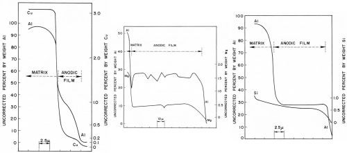
Figure 13 - Concentration profiles through sulfuric acid anodic films of aluminum and alloying elements on (a) Al-10Cu alloy, (b) Al-10Mg alloy and (c) Al-13Si alloy.
With the Al-10Cu alloy (Fig. 13a), although a rather thin anodic film of 6-7 microns was formed, it can be noted that the concentrations of both aluminum and copper more or less rapidly decreased across the anodic film; this was also found by Wood and Brock.8 The copper and aluminum concentration from the matrix to the anodic film fell rapidly within a very narrow region presumably throughout the barrier layer or in a region adjacent to it. At some distance away, the observed aluminum concentration dropped from about 35 wt% near the metal/oxide interface to about 5 wt% near the oxide/electrolyte interface. The copper concentration, over the same distance, dropped from about 0.3 to 0.1 wt%. The copper/aluminum concentration ratio varied from 0.03 in the metal to 0.01 both near the metal/oxide and oxide/electrolyte interfaces and this also suggests dissolution of copper in the anodic film. Spooner9 found that copper was insoluble to soluble in the electrolyte depending on the alloy and temper used. The decrease in both aluminum and copper concentrations throughout the anodic film suggests a gradual increase in oxide porosity from barrier layer to the oxide/electrolyte interface.
The slow-scan traces of the aluminum and magnesium through the Al-10Mg alloy anodic film (Fig. 13b) showed both to be fairly constant except, as expected, for a gradual decrease near the oxide/electrolyte interface. The results agreed very well with those of Wood and Brock8 although they used corrected values. The oxide/metal ratio for the magnesium was 0.07 (Table 3) suggesting leaching out of the magnesium. Also, comparison of the aluminum-magnesium ratio in the metal (7.5/92.5 = 0.08) with that of the anodic film (0.5/27 = 0.02) indicated that magnesium was dissolved in the electrolyte. Spooner and Ramous and Sticchi reported the magnesium to be partly soluble to soluble respectively (Table 3).
The concentration profile of the Al-13Si alloy (Fig. 13c) showed a fairly uniform aluminum concentration while the silicon concentration decreased only very slightly from matrix to anodic film and was also fairly uniform through the anodic film. Based on the observed values, the silicon-aluminum ratio in both the matrix and anodic film and the oxide/metal silicon ratio indicated that silicon was retained in the anodic film. Spooner agreed with our findings while Ramous and Sticchi reported silicon to be partially soluble.
The oxide/metal ratio for the rest of the elements (Table 3) indicated that iron was apparently soluble while silicon was retained in the anodic film in the Al-4Fe-8Si alloy, and both magnesium and zinc were soluble in the electrolyte in the Al-9Mg-3Zn and Al-9Zn-3Mg alloys (Table 3). Spooner and Ramous and Sticchi more or less agreed with our findings, as indicated in Table 3. Only a trace of titanium was detected in the matrix of the Al-1 Ti alloy so it was impossible to establish whether this element was retained in the anodic film or dissolved in the electrolyte.
Discussion
The sulfuric acid anodic behavior of the coarse inter-metallic compounds investigated revealed that Si, TiAl3 and beta AlFeSi were inert, beta AlMg was oxidized at a slightly faster rate than the matrix and dissolved, while the CuAl2 and the T phase were oxidized and readily dissolved in the electrolyte. The behavior of CuAl2, beta AlMg and Si agrees with the findings of various workers in this field. To our knowledge, it is the first time that the sulfuric acid anodic behavior of TiAl3 and T phase has been reported, although Guminski, et al.5 reported the oxalic acid anodic behavior of TiAl3, which was also inert. Fisher, et al.4 reported that Al2Mg3Zn3 (which could be associated with the T phase) was readily dissolved. Keller and his colleagues3 reported that beta AlFeSi oxidized as rapidly as the aluminum matrix, while we found that these intermetallic compounds were entirely inert. The differences in anodizing conditions between our work and that of Keller, et al. were not sufficient to explain the dissimilar behavior unless, in using constant current density, as Keller and his co-workers did, higher voltage is required resulting in some overheating effect and consequently oxidation of the intermetallic compound.
The inert constituents (Si, TiAl3, and beta AlFeSi) became trapped in the anodic films and fractured as a result of the stresses developed by anodic film growth. Pronounced scalloping of the anodic film occurred around these inert particles producing a non-uniform metal/oxide and oxide/ electrolyte interface. The formation of the scalloped interfaces depended on the particle orientation and was probably due to current shielding by these particles rather than to current thieving as suggested by Cooke.15 In commercial applications, the presence of abundant and uniformly-distributed small particles of these intermetallic compounds can be expected to result in the formation of integrally-colored anodic films. This also applies to the intermetallic compound MnAl6, reported previously.1 In fact, integrally-colored films are obtained with aluminum-high silicon alloys (AA-4043) and aluminum-manganese alloys (AA-3003) by anodizing in sulfuric acid as well as other types of electrolytes.
For those intermetallic compounds that were attacked, there was some evidence from the x-ray scanning images that the actual dissolution in the electrolyte was preceded by oxidation. This can be seen in the CuAl2 scanning images (Fig. 2). Those intermetallic compounds that were oxidized and dissolved more rapidly than the matrix (CuAl2, beta AlMg and T phase) showed only small scalloping effect of the anodic film around the particles. It appeared that, in these cases, current thieving15 by the intermetallic compounds was responsible for the scalloping effect.
Of the intermetallic compounds studied so far, those formed with manganese,1 silicon, titanium, and iron-silicon (beta AlFeSi) were inert; those formed with iron1 were oxidized, while those formed with chromium,1 copper, magnesium, magnesium-silicon,1 and zinc-magnesium were oxidized and dissolved. The exact relationship or relationships which determine the inertness or reactivity of individual intermetallic compound, for a given set of anodizing conditions, is not too clear. The crystallographic structure of the intermetallic compounds, their atomic bonding strength, atomic radius, electrode potentials, the degree of ionization under an electrical field, the solubility in the electrolyte of their reaction products, must be interrelated to some extent, determining whether an intermetallic compound is inert, oxidized, oxidized and dissolved, or possibly just dissolved in the electrolyte. Attempts to find correlation between normal electrode potential,8 crystallographic structure or atomic radius did not show a definite pattern to explain fully which intermetallic compounds should be inert or oxidized.
The use of observed chemical composition, from the ultra-slow scan of the electron probe microanalyzer, to establish the concentration profile and thereafter determine whether the solute elements were retained or dissolved in the anodic film is to some extent open to question. However, even if correction for absorption was made, this will not appreciably affect the general findings. Indeed, Wood and Brock8 reported a corrected aluminum content in the anodic film of about 50 wt% which would be about the same for the alloys used in our investigation. Therefore the criterion for retention or dissolution based on the corrected aluminum oxide/metal ratio1 would be approximately 0.5. Even if correction had been made for the alloying elements in the anodic film, their oxide/metal ratios would not have been greatly different from those based on the observed composition values and consequently the classification of the elements according to whether they are retained or dissolved would be about the same.
As is the case for intermetallic compounds, it is of interest to consider why solute elements are either retained or dissolved during the anodic process and what mechanisms are responsible. In either case, how are the structure and properties of the anodic film affected? Wood and Brock8 suggested that the incorporation of elements in the anodic film may possibly promote hydration of the anodic film or different crystallographic oxide forms resulting in an anodic film that could be more or less soluble. In cases where dissolution occurs, more porous films might be produced and the properties of the resulting anodic film could be affected. As yet, little is known about such changes, but there may be circumstances when such changes could be significant and this is an area where some further work could be beneficial.
Conclusion
By the use of electron probe microanalysis, it was found or confirmed that, during sulfuric acid anodizing, particles of Si, TiAl3, and beta AlFeSi are inert, while particles of CuAl2, beta AlMg and the T phase anodize faster than the aluminum matrix and are dissolved readily in the electrolyte. However, the anodizing behavior of large intermetallic compounds studied in this work, using high purity base aluminum alloys, may not be identical to that of similar constituents occurring in commercial alloys because such alloys are usually of lower purity. The elements in solid solution also respond differently during anodizing. Silicon is retained in the anodic film, zinc is partly dissolved, while copper, iron and magnesium are largely dissolved in the electrolyte.
References
1. J. Cote, E.E. Howlett, M.J. Wheeler and H.J. Lamb, Plating, 56, 386 (1969).
2. F. Keller and G.W. Wilcox, Metals and Alloys, 10 (6), 187 (1939).
3. F. Keller and G.W. Wilcox, M. Tosterud and C.D. Slunder, ibid., 10 (7), 219 (1939).
4. M. Fisher, M. Budiloff and L. Kock, Korrosion u. Metallschutz, 16 (718), 236 (1940).
5. R.D. Guminski, P.G. Sheasby and H.J. Lamb, Trans. Inst. Metal Finishing, 46, 44 (1968).
6. J. Herenguel and P. LeLong, Metal Finishing J. (London), 4 (1), 20 (1958).
7. P. Lacombe and L. Beaujard, Metal Treat., 12 (44), 223 (1945).
8. G.C. Wood and A.J. Brock, Trans. Inst. Metal Finishing, 44, 189 (1966).
9. R.C. Spooner, Plating, 53, 451 (1966).
10. E. Ramous and P. Sticchi, Alluminio, 36 (5), 247 (1967).
11. S. Wernick and R. Pinner, The Surface Treatment and Finishing of Aluminium and its Alloys, Robert Draper Ltd., Teddington, U.K.. 1964; Chapter 7.
12. G.H. Kissin, Finishing of Aluminum, Reinhold Publishing Corp., New York, NY, 1963; Chapter 2.
13. G.C. Wood, V.J.J. Marron and B.W. Lambert, Nature, 199 (7), 239 (1963).
14. The Aluminum Development Association, Equilibrium Diagrams of Aluminum Alloy Systems, Information Bulletin, 25, 24 (1961).
15. W.E. Cooke, Plating, 49, 1157 (1962).
16. L.S. Birks, Electron Probe Microanalysis, Interscience Publishers, New York, NY, 1963.
About the authors


Footnotes
*Silicon particles are second phase constituents rather than intermetallic compounds, but for simplicity throughout the study, the latter term has been used.
**T (AlZnMg) phase, or more simply, and hereafter, T phase.
*** Mica Wash No. 15, Springfield Facing Co., Springfield, Mass.
†Slow solidification approaching equilibrium conditions of a 1 wt% Ti alloy will produce an aluminum-rich solid solution at 665°C; on further cooling the TiAl3 will precipitate. In our slow cooled alloy, no intermetallic particles could be detected and the TiAl3 particles, if any, were too small to be noted.
††No attempt was made to determine the concentration profiles of the Al-Ti and the Al-Fe-Si alloys because in the former alloy no titanium was detected in the anodic film and similarly for iron in the AlFeSi alloy. Silicon in this latter alloy was assumed to have similar behavior to that of silicon in the Al-13 Si alloy. Similarly, no concentration profile was established with the AlZnMg alloys because the interaction of zinc and magnesium on each other during analysis was uncertain and because it has been reported8 that zinc distribution in anodic film on single alloy addition parallels the behavior of magnesium.
Related Content
Calculating Applied Media Force During Vibratory Finishing
What appear to be identically set-up vibratory bowls will finish identical loads of parts in varying time cycles. This paper offers a new technique to better predict what the operator will produce, by measuring the force applied to the parts. It is the efficiency of that force which controls the efficiency and speed of the refinement cycle.
Read MoreAESF Heritage: SUR/FIN 2000 – European Academy of Surface Technology: Copper Microelectrodeposition: The Influence of Different Additives on Growth in Microprofiles
In this work, a pH 3.0, 0.8M copper sulfate electrolyte was used for plating onto both blanket and patterned silicon wafers. This novel electrolyte, proposed by U. Landau, involves a number of beneficial effects with respect to the conventional bath.
Read MoreMaterial Database Enables Coating Thickness Measurement Without Calibration
The database from Coatmaster AG has calibrations of over 400 different RAL colors.
Read MoreRead Next
A ‘Clean’ Agenda Offers Unique Presentations in Chicago
The 2024 Parts Cleaning Conference, co-located with the International Manufacturing Technology Show, includes presentations by several speakers who are new to the conference and topics that have not been covered in past editions of this event.
Read MoreEpisode 45: An Interview with Chandler Mancuso, MacDermid Envio Solutions
Chandler Mancuso, technical director with MacDermid Envio discusses updating your wastewater treatment system and implementing materials recycling solutions to increase efficiencies, control costs and reduce environmental impact.
Read MoreDelivering Increased Benefits to Greenhouse Films
Baystar's Borstar technology is helping customers deliver better, more reliable production methods to greenhouse agriculture.
Read More


.jpg;maxWidth=300;quality=90)


