The Mechanism of Nickel Corrosion in ENEPIG Deposits and How to Mitigate It
The incident of nickel corrosion in ENEPIG multilayers (electroless nickel, electroless palladium and immersion gold) was brought to light after it was observed during the analysis of gold wire bond lifts.
Editor’s Note: The following is a synopsis of a presentation given at NASF SUR/FIN 2018, in Cleveland, Ohio on June 5, 2018 in Session 10, Sustainability: Research for Electronics and Surface Finishing. A pdf of this brief can be accessed and printed HERE; the complete Powerpoint presentation is available by clicking HERE.
ABSTRACT: The incident of nickel corrosion in ENEPIG multilayers (electroless nickel, electroless palladium and immersion gold) was brought to light after it was observed during the analysis of gold wire bond lifts. The separation occurred at the palladium nickel interface. This paper attempts to understand the mechanism under which nickel corrosion occurs. It is the result of a thin palladium, prolonged dwell time in the immersion gold bath and the intrinsic chemical corrosiveness of the immersion gold. Findings show that immersion gold preferentially plates at the expense of the underlying nickel, if accessible, thus creating corrosion. This is explained by the relative half potentials for nickel and gold relative to the half potentials for palladium and gold in the electromotive series. The paper will present mitigation actions to stay clear of this defect. Mitigation involves a minimum palladium thickness and employing a compatible gold, especially if a thicker layer of gold is a design requirement.
Introduction
Nickel corrosion in ENEPIG (Electroless Nickel / Electroless Palladium / Immersion Gold) multilayer deposits has been reported in multiple occasions and multiple applications. This was originally observed in cases where the desired gold thickness was in excess of 2.0 μ-in. (0.05 μm). Normally this is the result of circuit boards which were left in the gold bath for an extended dwell time or the result of electrolyte contamination (Cu, Ni). In those cases, the gold ion reaches through micro-pores (porosity) that are common in thinner palladium deposits. The gold ions can reach the underlying nickel and continue to deposit by corroding the underlying nickel. This paper on our work to reproduce the defect, and to determine the necessary “mitigation action” to avoid / minimize nickel corrosion in the ENEPIG finish.
The ENEPIG finish
The attributes of the ENEPIG finish are many. It presents a planar, solderable precious metal electrical contact finish with a good shelf life of 12 months at minimum. It does not tarnish and is aluminum or gold wire bondable. The underlying nickel acts to strengthen plated through-holes and, as a barrier layer, prevents basis metal copper dissolution to solder joints during assembly and rework.
According to IPC Specification 4556,[1] the thickness specifications for an ENEPIG coating over a copper substrate, as measured on a 60 x 60 mil pad or equivalent, are as follows:
• Electroless nickel (EN) 120-240 μ-in.
• Electroless palladium (EP) 2 μ-in. minimum at -4σ from the process mean to 12 μ-in maximum at +4σ from the process mean.
• Immersion gold (IG) 1.2 μ-in. minimum at -4σ from the process mean to 2.8 μ-in.
Immersion gold
Our analysis required consideration of the chemistry of the immersion gold process. The immersion gold reaction is an exchange reaction between the gold ions in solution and the substrate basis metal:
2Au+ + 2e– ⇒ 2Au
Pd ⇒ Pd+2 + 2e–
Ni ⇒ Ni+2 + 2e–
The substrate metal (Ni or Pd) is oxidized to the respective metal ion giving up electrons. The gold ion picks up electrons and is reduced to gold metal. The driving force for these reactions follows the electromotive series (Table 1).
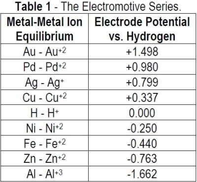
By selecting metals and their oxidation potentials, the driving force for the reaction is the difference between the two half reactions:
(a) Immersion gold on nickel:
Ni ⇒ Ni+2 + 2e– (-0.250 V)
Au+2 + 2e– ⇒ Au (+1.498 V)
Driving Force = -0.250V - (+1.498 V) = -1.740 V.
(b) Immersion gold on palladium
Pd ⇒ Pd+2 + 2e– (+0.987 V)
Au+2 + 2e– ⇒ Au (+1.498 V)
Driving force = +0.987 V - (+1.498 V) = -0.511 V
Thus, the immersion gold reaction on nickel proceeds at a much faster rate than on palladium. The immersion gold reaction on palladium proceeds at a lower rate and can only achieve a limited gold thickness. Immersion gold thicknesses on palladium are on the order of 1.2 - 2.0 μ-in. (0.03 - 0.05 μm).
Experimental considerations
The expectation is that nickel corrosion would not occur in ENEPIG, as the gold ions have no direct access to the nickel. This would be true if the palladium layer was non-porous and therefore impervious to the gold ions. If the palladium layer is thinner (< 4 μ-in. / 0.1 μm), we know that it is not totally impervious and the gold ions have access to the underlying nickel, thereby proceeding with the preferred and faster reaction path to immersion gold deposition. Nickel corrosion therefore would occur, and the gold would be deposited on the palladium top layer.
Given this, the effect of the following attributes in allowing nickel corrosion to occur were investigated:
- The thickness of the electroless palladium layer required to limit / minimize the corrosion of nickel
- The effectiveness of different types of electroless palladium (phosphorus vs non-phosphorus) formulations, and
- The type of immersion gold (standard immersion vs “Reduction-Assisted” immersion gold) that was used.
Experimental design
The test vehicle (Fig. 1), used in this study consisted of a double-sided, copper-clad laminated substrate which was copper plated to a thickness of 20 μm using an acid copper electroplating process. ENEPIG was deposited on the test vehicle using two different types of electroless palladium with two different types of gold.
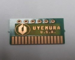
Figure 1 - Test vehicle used in this study.
The nickel deposit (7 - 8% phosphorus) was a single source and bath type and was deposited at a fixed thickness of 225 - 275 μ-in (5.6 - 6.9 μm). The electroless palladium baths were, (1) a phosphorus-palladium with ~4.0% P in the deposit and (2) a non-phosphorus palladium (0% P).
Two different gold baths were chosen for this investigation. The first was a standard immersion gold bath that ran at a mildly acidic pH of ~5.5 at a temperature of 180°F. The second gold bath was a “Reduction-Assisted” immersion gold (RAIG) bath also known as a “Mixed Reaction” bath. The RAIG bath combines both an immersion and an autocatalytic (electroless) bath reaction in one electrolyte. The bath composition includes a reducing agent for the autocatalytic reaction. The deposition of gold in the RAIG reaction does not depend on the substrate immersion reaction oxidation alone.
The thickness of the palladium deposit was varied by changing the dwell time in each of the two baths. The rate of deposition was recorded over time. The samples at different layer thicknesses of Ni-Pd layers were placed in the immersion gold bath for exaggerated dwell times of 30 minutes. The exaggerated dwell in the gold bath was designed to ensure that some level of nickel corrosion would occur and that we would be able to see the role that the thickness of the palladium layer plays in mitigating nickel corrosion.
The study was comprised of three tests:
- Varying the thickness of the phosphorus-palladium with standard immersion gold.
- Varying the thickness of non-phosphorus palladium with standard immersion gold
- Varying the thickness of phosphorus-palladium with RAIG.
The experimental process design is shown in Table 2.
Table 2 - Experimental process design.
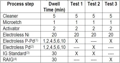
After each test, cross sections of the ENEPIG layer, at different palladium thickness were evaluated for nickel corrosion. Thickness was measured using a Seiko SEA-5120 Element Monitor MX XRF. The cross-section images of the pads of the through-holes were observed using a JEOL JSM-6010LA SEM.
Results
Test #1 - Varying the thickness of the phosphorus-palladium with standard immersion gold.
Samples were prepared as per the regimen in Table 2, varying the thickness of the phosphorus-palladium portion of the ENEPIG multilayer and using the exaggerated IG process time of 30 min. The thickness results are compiled in Table 3 and shown graphically in Fig. 2
Table 3 - Phosphorus-palladium thickness at different dwell times and the corresponding thickness of 30-min of immersion gold.
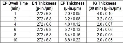
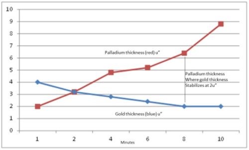
Figure 2- Thicknesses of phosphorus-palladium and immersion gold vs. dwell time in the palladium bath.
The electroless phosphorus-palladium is seen to increase, almost linearly, over the 10-min process time. The 30-min immersion gold thickness decreases with phosphorus-palladium process time to the point where the gold thickness stabilizes at 2.0 μ-in. (0.05 μm), on the phosphorus-palladium deposits processed for 8 min and greater. The thicker gold deposits in the specimens from the early stages of immersion phosphorus-palladium deposition suggest still-incomplete coverage or porosity in the thinner Pd deposits and thus exposure to electroless nickel with its larger electrochemical driving force. This is borne out with the cross-sectional photos shown in Fig. 3.

Figure 3 - Evaluation of nickel corrosion with increasing phosphorus-palladium thickness.
Nickel corrosion is seen to decrease as the phosphorus-palladium layer builds up. At 2.0 μ-in. (0.05 μm), nickel corrosion is extensive, albeit shallow. Exposure to the underlying electroless nickel is still extensive. At 4.8 μ-in. (0.12 μm), a few intermittent deep corrosion spikes are observed. Finally, at 8.8 μ-in. (0.22 μm), no nickel corrosion is observed.
Test #2 - Varying the thickness of the non-phosphorus palladium with standard immersion gold.
Samples were prepared as per the regimen in Table 2, varying the thickness of the non-phosphorus palladium portion of the ENEPIG multilayer and using the exaggerated IG process time of 30 min. The thickness results are compiled in Table 4 and shown graphically in Fig. 4.
Table 4 - Non-phosphorus palladium thickness at different dwell times and the corresponding thickness of 30-min of immersion gold.
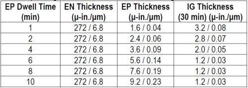

Figure 4- Thicknesses of non-phosphorus-palladium and immersion gold vs. dwell time in the palladium bath.
As with the phosphorus-palladium, the electroless phosphorus-palladium is seen to increase almost linearly over the 10-min process time. As before, the 30-min immersion gold thickness decreases with phosphorus-palladium process time. However, the point where the gold thickness stabilizes occurs sooner, i.e., on the phosphorus-palladium deposits processed for 6 min and greater, and the “stable” gold layer is thinner, 1.2 μ-in. (0.03 μm). The effects of still-incomplete coverage or porosity in the thinner Pd deposits and thus exposure to electroless nickel with the larger electrochemical driving force, are still evident in the cross-sectional photos shown in Fig. 5.

Figure 5 - Evaluation of nickel corrosion with increasing non-phosphorus palladium thickness.
Overall, nickel corrosion is less severe, but it still decreases as the phosphorus-palladium layer builds up. At 1.6 μ-in. (0.04 μm), nickel corrosion is extensive, but still shallow. At 3.6 μ-in. (0.09 μm), A few intermittent deep corrosion spikes are observed. Finally, at 7.6 μ-in. (0.19 μm), no nickel corrosion is observed. In general, the effects are less severe, and the sequence tends to play out at somewhat lower Pd thicknesses.
Test #3 - Varying the thickness of phosphorus-palladium with reduction-assisted immersion gold.
Samples were prepared as per the regimen in Table 2, varying the thickness of the phosphorus-palladium portion of the ENEPIG multilayer and using the exaggerated IG process time of 30 min. Here the RAIG process replaced the standard immersion gold in Test #1. The thickness results are compiled in Table 5 and shown graphically in Fig. 6.
Table 5 - Phosphorus-palladium thickness at different dwell times and the corresponding thickness of 30-min of reduction-assisted immersion gold.
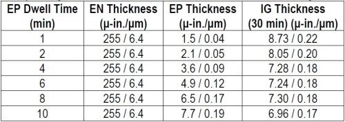
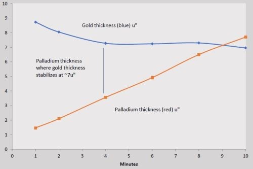
Figure 6- Thicknesses of phosphorus-palladium and reduction-assisted immersion gold (RAIG) vs. dwell time in the palladium bath.
As with the tests using the standard immersion gold, the electroless phosphorus-palladium increases almost linearly over the 10-min process time. Here, the RAIG immersion gold deposits at a significantly higher rate, and, the point where the gold thickness stabilizes occurs sooner, i.e., on the phosphorus-palladium deposits processed for 4 min and greater. The nickel corrosion is virtually eliminated, as seen in the cross-sectional photos shown in Fig. 7. At 2.0 μ-in. (0.04 μm), nickel corrosion is nearly non-existent, but for an anomaly in the substrate. At 6.4 μ-in. (0.19 μm), no nickel corrosion is observed.
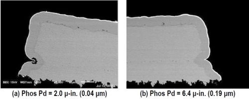
Figure 7 - Evaluation of nickel corrosion with increasing phosphorus-palladium thickness using reduction-assisted immersion gold.
Mitigation of nickel corrosion
The data clearly indicates that increasing the thickness of the palladium layer in the range of 6 - 8 μ-in. would go a long way towards minimizing nickel corrosion in ENEPIG. Presently the IPC-4556 Specification for ENEPIG specifies for 2 - 12 μ-in. (0.05 - 0.3 µm) for the EP layer and 1.2 - 2.8 μ-in. (0.03 – 0.07) μm for immersion gold. The authors recommend increasing the lower limit of the EP thickness to 7 μ-in. (0.18 μm).
The increased dwell time in the immersion gold bath is designed to achieve higher thicknesses, which in turn will create a level of nickel corrosion, particularly at the lower EP thickness. IG gold baths should always be run per vendor specification as far as gold concentration, temperature, pH, dwell time and age of bath or MTOs (metal turnovers). If a thicker layer of immersion gold is a design criterion, “reduction-assisted” immersion gold should be specified. This type of gold bath will deposit gold up to 8 μ-in. (0.2 μm) with no significant nickel corrosion in the ENEPIG deposit.
Summary
Nickel corrosion in ENEPIG was reproduced using an exaggerated dwell time in the immersion gold bath. Nickel corrosion will occur at the manufacturing site if there is an attempt to plate thicker (>2.8 μ-in. / 0.07 μm) gold with standard immersion gold chemistry. A different gold bath, specifically “reduction-assisted” Immersion gold was shown to be capable of depositing higher thickness of gold without compromising the nickel substrate.
About the authors

George Milad has 30 years of experience in PWB manufacturing. He is the National Accounts Manager for Technology at Uyemura International Corporation. Other positions held include: Technical Marketing Manager at RHEM, Director of Applications at Atotech and Engineering Manager at Automata PWB. He is the author of the chapters on “Plating” and “Surface Finishing” in Clyde Coomb’s Printed Circuit Handbook, Fifth Edition, 2001. He is the recipient of the IPC 2009 President’s award. He presently chairs the Plating Committee and is a permanent member of the Technical Activities Executive Committee of the IPC.

Jon Bengston is the Research Manager with UIC America. Mr. Bengston holds numerous patents and has also been an author and presenter of technical papers relating to electronic and industrial finishing chemistries and supporting processes throughout his 35 plus year career.

Don Gudeczauskas is Vice President and Technical Director at UIC / Uyemura International Corporation. Don has Bachelors and Masters degrees in Metallurgical Engineering from the Colorado School of Mines. He has authored several papers on surface finishes and has worked with ENIG and other alternate final finishes since their introduction into North America in the late 1990s.

Richard DePoto is a Business Development Manager with Uyemura International Corporation Southington, CT. Richard is currently focusing on expanding the applications and use of tri-metal coatings in the electronics and GMF industries. He holds a Bachelor of Science degree in Chemical Engineering from Stony Brook University in New York. Richard has been in involved with electroless and electroplating for the past 30 years and has held numerous positions in engineering, manufacturing and applied development, most notably AMP-AKZO Corporation.
*Compiled by Dr. James H. Lindsay, Technical Editor - NASF
** Corresponding author:
George Milad
National Accounts Manager for Technology
Uyemura International Corporation
240 Town line Rd
Southington, CT 06489
Office: (860) 793-4011; x226
Cell: (516) 901-3874
E-mail: GMilad@uyemura.com
[1] IPC 4556, “Specification for Electroless Nickel/Electroless Palladium/Immersion Gold (ENEPIG) Plating for Printed Circuit Boards,” IPC, Bannockburn, IL (Amended 2015)
Related Content
Possibilities From Electroplating 3D Printed Plastic Parts
Adding layers of nickel or copper to 3D printed polymer can impart desired properties such as electrical conductivity, EMI shielding, abrasion resistance and improved strength — approaching and even exceeding 3D printed metal, according to RePliForm.
Read MoreAn Overview of Electroless Nickel Plating
By definition, electroless plating is metal deposition by a controlled chemical reaction.
Read MoreSuccessful South African Plater Beating the Odds
Remaining focused on quality and reliability, Team Plating Works stays profitable in a volatile and challenging economy.
Read MoreTrivalent Chrome Overview
As the finishing industry begins to move away from the use of hexavalent chromium to trivalent chromium, what factors should finishers consider as they make new investments? Mark Schario, chief technology officer for Columbia Chemical offers a helpful overview of this complicated topic.
Read MoreRead Next
Delivering Increased Benefits to Greenhouse Films
Baystar's Borstar technology is helping customers deliver better, more reliable production methods to greenhouse agriculture.
Read MoreA ‘Clean’ Agenda Offers Unique Presentations in Chicago
The 2024 Parts Cleaning Conference, co-located with the International Manufacturing Technology Show, includes presentations by several speakers who are new to the conference and topics that have not been covered in past editions of this event.
Read MoreEducation Bringing Cleaning to Machining
Debuting new speakers and cleaning technology content during this half-day workshop co-located with IMTS 2024.
Read More


