The Nature, Cause and Effect of Porosity in Electrodeposits: A Microscopic Examination of Nickel-Chromium Coatings after Atmospheric Corrosion
This paper is one of seven reports constituting AES Research Project #13, dealing with the nature, cause and effect of porosity in electrodeposits, performed at the then-National Bureau of Standards, in Gaithersburg, Maryland. It was one of several seminal articles produced through AES Research during the height of the automotive/decorative segment of the surface finishing industry in the 1950s and 60s.
by
Donald W. Ernst and Fielding Ogburn
National Bureau of Standards
[now National Institute for Standards and Technology (NIST)]
Gaithersburg, Maryland, USA
Editor’s Note: Originally published as Plating, 48 (5), 491-497 (1961) and as AES Research Report, Serial #47, this paper is one of seven reports constituting AES Research Project #13, dealing with the nature, cause and effect of porosity in electrodeposits, performed at the then-National Bureau of Standards, in Gaithersburg, Maryland. It was one of several seminal articles produced through AES Research during the height of the automotive/decorative segment of the surface finishing industry in the 1950s and 60s. A printable PDF version of this report is available by clicking HERE.
ABSTRACT
Nickel-chromium coatings on steel, which had been subjected to atmospheric corrosion, were examined microscopically. With chromium, bright nickel was perforated more by pitting corrosion than Watts nickel, but the latter contained many more micropits. Pits which did not extend to the basis metal were similar in appearance regardless of type of nickel or atmosphere. Cracks appeared in chromium plated bright nickel after pits had formed in the nickel. Observations of galvanic cells in the laboratory showed that the polarity of the nickel-steel couple changes with variations in the electrolyte. These changes can explain differences in pit shapes and in rust exudation associated with sea coast and industrial atmospheres. Also the polarity of nickel-chromium couples was found to change unpredictably in several electrolytes. The chromium was usually found to be the anode. A nickel-bright nickel cell was found to be more active than any nickel-chromium cell.
Introduction
Investigations have been made of the atmospheric corrosion of nickel-plated steel with and without chromium. In most of these investigations, the nature and extent of the corrosion have been determined solely by visual observations, with the unaided eye, of the exposed surfaces of the coatings. These investigations have produced valid and useful information. To understand the nature of the corrosion process, however, one needs to have more information than is obtainable from visual appearance. For example, information is needed about the microscopic nature of the corroded surfaces of the metal, the history of the defects which ultimately lead to rust spots, and the galvanic effects which are of significance.
An important purpose of this project was to explore some new approaches to the investigation of the corrosion of nickel-plated steel. The first part of this final report of Project 13 covers the microscopic examination of a number of steel panels plated with nickel, or chromium and nickel, which had been exposed outdoors. The second part of the paper covers the microscopic examination of a few panels before and during outdoor exposure. A third part deals with a few exploratory experiments related to the galvanic corrosion of couples of iron, nickel, and chromium.
Examination of specimens after outdoor corrosion
The specimens* which were examined consisted of one-half of standard 4 × 6 inch (10 × 15 cm) steel corrosion test panels, each plated with one of the following coatings:
| Designation | Coating |
| WU | Watts nickel, unbuffed |
| WB | Watts nickel, buffed |
| WB, Cr | Watts nickel, buffed, with chromium |
| A | Bright nickel A |
| A, Cr | Bright nickel A with chromium |
| B | Bright nickel B |
| B, Cr | Bright nickel B with chromium |
| TT | Double-layer nickel (semi-bright and bright) |
| TT, Cr | Double-layer nickel with chromium |
Each specimen was plated with about 38 μm (1½ mils) of nickel. The chromium was the usual decorative chromium, about 3 μm (0.01 mil) thick. One set of these specimens had been exposed at Kure Beach, North Carolina, a rural sea coast atmosphere, 250 meters (800 feet) from the ocean, and a second set had been exposed at Bayonne, New Jersey, an industrial atmosphere. Both sets had been exposed for about nine months. There is no record available of the progress of corrosion of these specimens insofar as a detailed microscopic examination and classification of the corrosion pattern is concerned.
The surface of each coating was cleaned and carefully examined microscopically. Cross sections and parallel sections were also examined. Uniform surface attack or etching of the surface appears under the microscope as a multitude of tiny pits randomly distributed. This general surface etching seems to be more pronounced at Bayonne than at Kure Beach. There was, however, no apparent difference in the extent of the surface attack on the different types of nickel such as has been reported from visual observations.
Superimposed on the uniformly attacked surface are the corrosion pits, (including rust spots, which are deep pits filled with rust) which appear as relatively large dark spots or areas (surface view) or as relatively wide and deep cavities (cross section view). These pits occurred principally in two forms as single isolated pits with vertical sides and as clusters of shallow pits. Both types of pits formed at both exposure sites. Examples of each are shown in Figs. 1 and 2 which are photographs of specimens described in the next section of this paper.
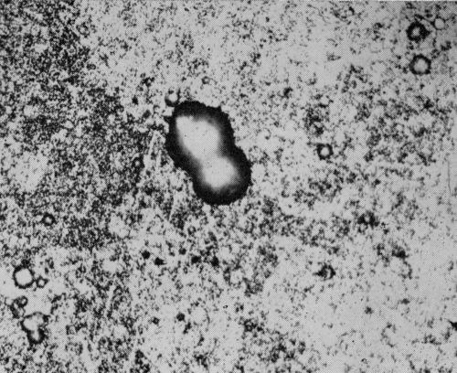
Figure 1 - Surface view of bright nickel A coating without chromium exposed for 49 days at Bayonne. Pit in center is 20 μm (0.8 mil) deep. The surrounding area is illustrative of uniform surface attack. (Original magnification 400×)
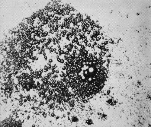
Figure 2 - Surface view of bright nickel A coating without chromium with cluster of pits found after 120 days exposure at Kure Beach. Usually those pits were on the order of 7 μm (0.3 mil) deep and they surround a much deeper pit. (Original magnification 400×)
The presence of a thin chromium coating over the nickel had a marked effect on the corrosion of the specimens. Figures 3 and 4 are representative micrographs of the chromium plated specimens. The chromium surface is not subject to the general surface etching characteristic of nickel. The chromium layer, however, is obviously perforated and the nickel has been attacked at each perforation of the chromium coating. Thus, in contrast to nickel coatings without chromium, the chromium-nickel coatings had relatively large un-corroded areas.
There were distinctive differences between the pits in chromium plated Watts nickel and chromium plated bright nickel. In the Watts nickel there were many shallow pits, about 150/cm2 (1000/in.2) in specimens exposed at Kure Beach and 300/cm2 (2000/in.2) at Bayonne, and virtually no rust spots. These shallow pits were too small to see with the unaided eye. The bright nickels, on the other hand, contained considerably fewer pits, about 4/cm2 (30/in.2) in specimens exposed at Kure Beach and 16/cm2 (100/in.2) at Bayonne. Most of these pits were rust spots at Kure Beach and crow's-feet at Bayonne. These differences between Watts and bright nickel are significant with respect to corrosion mechanism, but the reader should bear in mind that they were observed after nine months of exposure. Another year of exposure might have drastically altered the picture.
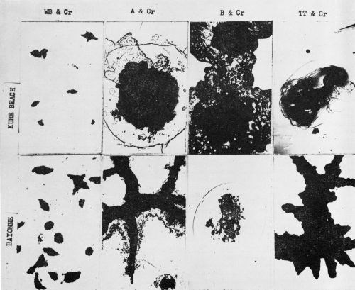
Figure 3 - Surface views of the chromium-plated nickel coatings exposed 9 months at Kure Beach and Bayonne. Rust has been removed. These individual failures are typical of all the failures. (200×)
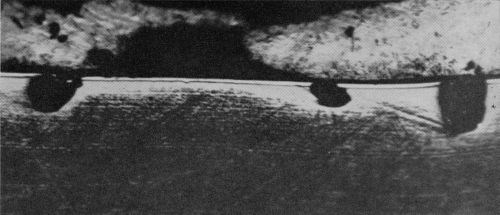
Figure 4 - Cross section of bright nickel A with chromium showing pits extending through chromium layer into the nickel layer. Exposed at Bayonne for 9 months. (400×)
Crow's-feet are pits with distinctive shapes similar to that shown in Fig. 5A. They are frequently found in chromium plated bright nickel coatings that have been exposed to industrial atmospheres. Usually they extend through the coating to the steel and contain some rust. The four micrographs in Fig. 5 are parallel sections** of a crow's-foot and indicate that the sides of the pit slope towards the central area of the pit so that the steel is exposed only in the center.
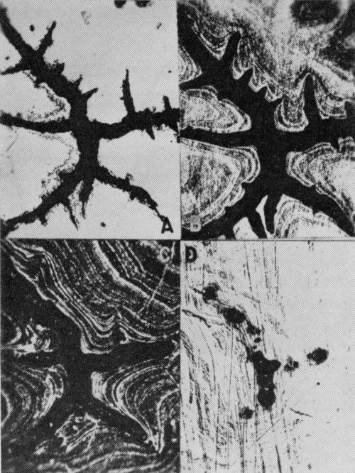
Figure 5 - Parallel section series showing the shape of a crow's-foot at various deposit thicknesses (bright nickel A exposed at Bayonne for 9 months): (A) top surface appearance; (B) chromium layer just removed (note slight enlargement of crow's-foot); (C) approximately one-half way through the deposit; (D) close to basis metal; rust is found in the largest group of pits. (200×)
Microscopic examination of the chromium surfaces revealed numerous foreign particles adhering to the chromium. Many of these were surrounded by colored circles or interference bands and, not infrequently, a pit had formed beneath or adjacent to the particle. Figure 6 shows two micrographs of this phenomenon which suggests that perforation of the chromium coating may sometimes be attributable to dust particles from the atmosphere.
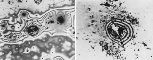
Figure 6 - (Left) Dust particles surrounded by varied colored bands. This was frequently found on the chromium-plated coatings. (Original magnification 400×); (Right) Enlarged view of failure in an area similar to the top photomicrograph. (Original magnification 800×)
Cracks were also found in the chromium-plated bright nickels. These cracks were always associated with pits as shown in the micrographs of Fig. 7. By parallel sectioning of these cracks, it was found that they extended through the nickel coating to the basis metal, but no evidence was found of corrosion of the steel at the base of the crack except at a few isolated points, although the associated pit contained rust.
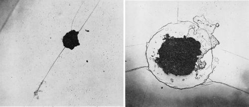
Figure 7 - (Left) Straight-line crack on bright nickel A with chromium. Nine months exposure at Kure Beach. (Original magnification 200×); (Right) Circular crack on bright nickel A with chromium. Nine months exposure at Kure Beach. (Original magnification 200×)
Examination of specimens during outdoor exposure
Consideration of the failures mentioned in the preceding section leads to the question of how these failures developed during the earlier stages of the corrosion process and of what defects were originally present in the coating that would lead to these failures. It was possible to obtain four panels plated with bright nickel A, two of which were with chromium, and two without chromium, which had been plated under conditions similar to the original panels, but were not necessarily identical. One panel from each pair was exposed at Bayonne and at Kure Beach. These specimens were examined microscopically before exposure and after various intervals ranging from three days to three weeks.
The original examination revealed some accidental scratches which subsequently led to corrosion of the nickel before any other corrosion was observed (Figs. 8 and 9). Also observed were a few fine lines or "cracks" in the chromium surface such as shown in Fig. 10. These appeared distinctly different from the cracks mentioned earlier and shown in Fig. 7. During the 11 weeks of exposure at Bayonne and 20 weeks at Kure Beach no corrosion or pitting was evident at these "cracks."

Figure 8 - Scratched chromium surface. Pit on scratch at lower right and spreading of scratch at upper left appeared after 12 days exposure at Bayonne. No other corrosion attack of the coating was evident. (Original magnification 400×)
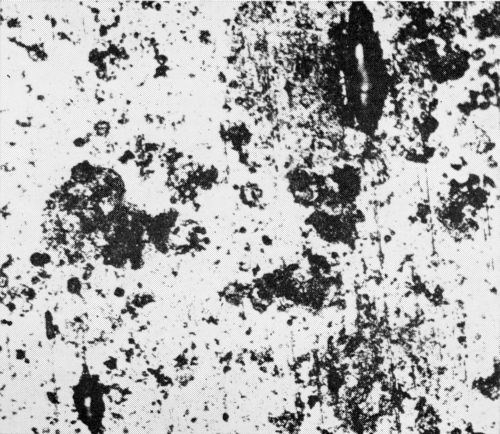
Figure 9 - Bright nickel surface (without chromium) exposed at Kure Beach. Corrosion was more severe along scratches. (Original magnification 400×)
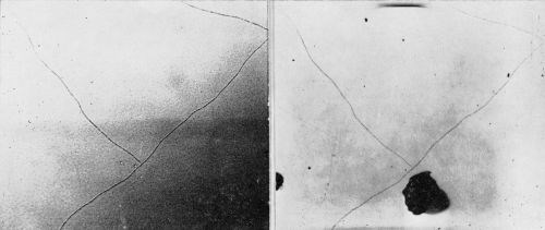
Figure 10 - Surface of chromium plated bright nickel A illustrating "cracks," which did not change in appearance during 74 days exposure at Bayonne or 143 days exposure at Kure Beach. (Original magnification 400×)
The microscopic exploration revealed no other defects in the as received coatings to which subsequent pitting or cracking could be attributed with any reasonable degree of assurance. During the outdoor exposures, pits developed and grew with time and ultimately became rust spots. It was noted that the first rust spots did not appear until the measured depths of the deepest pits approximated the coating thickness. This seemingly obvious observation is mentioned because rust spots have often been attributed to initial porosity as opposed to pitting. Actually rust spots may be attributed to both initial porosity and pitting corrosion of the coating.
Also of interest was the appearance, in the chromium-plated samples, of cracks and associated pits similar to those found on the original set of specimens and shown in Fig. 7A. These cracks (Fig. 11) did not become visible until the pits were well developed, and each crack was associated with a pit.
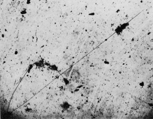
Figure 11 - Crack found on bright nickel A with chromium after 100 days of exposure. Micrograph was taken after 140 days of exposure.
The discussion in the previous section mentioned, indirectly, differences in pits and rust spots depending on the exposure atmosphere. After the nine months exposure, crow's-feet were quite prevalent on the chromium plated bright nickels exposed at Bayonne, but not at Kure Beach. During the early stages of corrosion of the set of four specimens, however, no such differences appeared. At both locations, the pits developed similarly and looked the same (Figs. 12 and 13). More will be said about this in the following paragraphs.
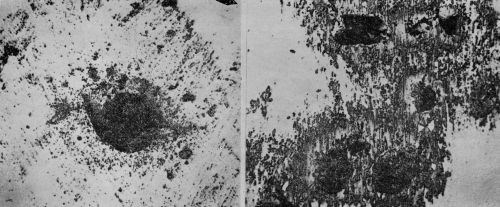
Figure 12 - Chromium plated bright nickel exposed at Bayonne for 61 days (left) and 36 days (right). from atmosphere has not been removed. (Original magnification 400×)
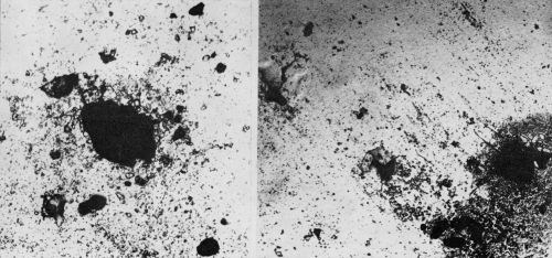
Figure 13 - Chromium plated bright nickel exposed at Kure Beach for 120 days (Left) and 80 days (Right). Large black areas are pits. Debris from atmosphere has not been removed. (Original magnification 400×)
Galvanic corrosion
Concurrently with the examination of the corroding specimens, an exploratory study was made of galvanic couples, such as might be encountered during the corrosion of nickel and chromium plated steel. For many of the experiments, but not all of them, a cell was used such as shown diagrammatically in Fig. 14. Static and dynamic electrode potentials were measured with a calomel electrode and a conventional potentiometer circuit. Short circuit currents were measured with a zero resistance ammeter circuit (Fig. 15). Numerous electrolytes were used in a stagnant condition, without any effort to control the oxygen content. Such measurements are not highly reproducible because the currents change with time. However, they do produce useful information.
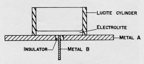
Figure 14 - Cell used for measuring galvanic effects. (Side view.) Wire or brad of Metal B is inserted in hole drilled in center of disk of Metal A. Space between two metals is filled with an insulating material. Metal A may be sheet steel plated with another metal.
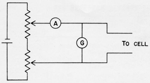
Figure 15 - Zero resistance ammeter circuit. When the potentiometers are adjusted so that there is no deflection of the galvanometer, the ammeter gives the short circuit current flowing through the cell.
Three of the observations made are of especial significance to the pitting corrosion discussed in this paper.
- When Watts nickel was coupled with steel in sodium chloride solutions, the steel was the anode. In an acidic sodium sulfite solution, however, the nickel became the anode. Assuming these electrolytes are representative of the electrolytes encountered in sea coast and industrial atmospheres, respectively, the observations suggest that galvanic effects are responsible for differences in pitting characteristics. After a pit in the nickel has reached the underlying steel, subsequent corrosion will be greatly influenced by the electrolyte. At Kure Beach one would expect the steel to be the anode and this agrees with the relatively rapid rate of rust formation frequently observed. One would expect the steel to be much less anodic or even cathodic to the nickel at Bayonne. This would be in conformity with the observed slower rate of rust formation in the pits and the lateral corrosion of the nickel to produce the crow's-feet. The actual shape of the crow's-foot is probably attributable to the manner in which the chromium layer breaks off as it is undercut by corrosion of the nickel.
- Nickel and chromium were coupled together in a number of different solutions such as sodium chloride, sodium sulfate, sodium nitrite, sulfurous acid and sulfuric acid, each at various pH values. Usually the chromium was the anode. Nickel was anodic occasionally, but not consistently in any given solution. The inconsistencies may be attributed to the oxygen content of the electrolytes or to the surface condition of the metals, neither of which were kept under control. The point of significance here is that the commonly accepted view of chromium being cathodic to electrodeposited nickel*** cannot be accepted without reservations. It is unquestionable that atmospheric exposure of nickel-chromium coatings results in chemical attack of the nickel and no visibly evident attack of the chromium. The laboratory experiments indicated, however, that it cannot be assumed that the nickel is always the anode.
- The short-circuit current between Watts nickel and bright nickel (addition agent: benzene disulfonate) in several of the common electrolytes was always considerably greater than between chromium and either type of nickel. This indicates that the galvanic effects between two types of nickel can be appreciable and supports the explanation usually given for the performance of double-layer nickel coatings.
Discussion
Because of climatic variations and uncontrolled features of plating processes, the reproducibility of exposure tests is poor. This, along with the very limited scope of the observations reported here, precludes any firm conclusions other than that much is to be learned about the corrosion process of plated coatings by more detailed and careful examination of corroding specimens. The reported observations do contribute to the overall knowledge of the subject and suggest conclusions which need to be confirmed by more extensive observations.
With the help of these observations, one can build up the following generalized picture of the corrosion process. This picture serves only to put some facts in an orderly scheme and is expected to be altered as more facts are brought to light.
The decorative chromium coating is assumed to be porous in the "as plated" condition and to be essentially immune to chemical attack by the atmosphere. Initial corrosion occurs through the minute pores in the chromium. Thus, pitting of the nickel is started and as the pits grow downward and outwards, the chromium is undercut and broken off at the edges by mechanical forces, leaving a larger hole in the chromium and allowing more extensive corrosion of the nickel.
The number of pits is determined primarily by the porosity of the chromium, and, at least from our limited observations, is greater for chromium plated over buffed Watts nickel than over bright nickel. The rate of attack of the nickel is, of course, determined by the environment and, because of the galvanic cell created by the chromium covering the nickel, the nickel corrodes somewhat more rapidly than it would in the absence of chromium (Nickel exposed by discontinuities in the chromium generally corrodes more rapidly than the general surface of the same nickel without chromium.). The rate may also be related to the ratio of the anode to cathode area of the chromium-nickel cell. If so, an inverse relation between the number of pits per unit area and the rate of pit growth can be expected.
The pits continue to grow laterally and vertically, eventually exposing the basis metal (Where initial porosity of the nickel coating exists, this corrosion process will be by-passed.). The nature of subsequent corrosion depends to a large extent on the basis metal and on the atmosphere or electrolyte present. If the basis metal is steel and the electrolyte is such that the steel is anodic and the electrical currents are quite pronounced, corrosion of the nickel is retarded and rust forms rapidly, filling up the pits and exuding over the chromium surface. If rust formation continues, the nickel layer is undercut and may be broken off by mechanical forces, thus enlarging the pit. In an industrial atmosphere, the electrolyte may be such that the steel is much less anodic or even cathodic to the nickel and the electrical currents are relatively weak. Under such conditions, the steel corrodes relatively slowly and the nickel may corrode more rapidly, rust formation is retarded and lateral growth of the pits proceeds by corrosion of the nickel. As the chromium is undercut, it breaks off in a pattern determined by its structure and stress pattern. This leads to the odd shapes such as stars or crow's-feet that have been observed on many occasions.
This picture does not include any cracks in the nickel such as mentioned earlier. While they did not seem to contribute significantly to the appearance and failure of the coating, it is quite possible that they would play a more important role after longer exposures.
The shapes of a number of the pits in the nickel coatings without chromium are reminiscent of the etch pits commonly associated with dislocations. The similarity is sometimes quite pronounced and suggests that corrosion of the electrodeposited nickel is influenced by grain structure as well as by factors external to the grains.
Footnotes
*The corroded specimens were provided by the International Nickel Company.
**Parallel sections refer to sections of the coating produced by polishing parallel to the coating surface. This is in contrast to cross sections which are cut and polished perpendicular to the plane of the coating. See F. Ogburn and D. Ernst, Plating, 46, 831 (1959).
***H. Brown, M. Weinberg and R. J. Clauss, Plating, 45, 144 (1958).
About the authors


Related Content
Material Database Enables Coating Thickness Measurement Without Calibration
The database from Coatmaster AG has calibrations of over 400 different RAL colors.
Read MoreAESF Heritage: SUR/FIN 2000 – European Academy of Surface Technology: Copper Microelectrodeposition: The Influence of Different Additives on Growth in Microprofiles
In this work, a pH 3.0, 0.8M copper sulfate electrolyte was used for plating onto both blanket and patterned silicon wafers. This novel electrolyte, proposed by U. Landau, involves a number of beneficial effects with respect to the conventional bath.
Read MoreCalculating Applied Media Force During Vibratory Finishing
What appear to be identically set-up vibratory bowls will finish identical loads of parts in varying time cycles. This paper offers a new technique to better predict what the operator will produce, by measuring the force applied to the parts. It is the efficiency of that force which controls the efficiency and speed of the refinement cycle.
Read MoreRead Next
Education Bringing Cleaning to Machining
Debuting new speakers and cleaning technology content during this half-day workshop co-located with IMTS 2024.
Read MoreEpisode 45: An Interview with Chandler Mancuso, MacDermid Envio Solutions
Chandler Mancuso, technical director with MacDermid Envio discusses updating your wastewater treatment system and implementing materials recycling solutions to increase efficiencies, control costs and reduce environmental impact.
Read MoreA ‘Clean’ Agenda Offers Unique Presentations in Chicago
The 2024 Parts Cleaning Conference, co-located with the International Manufacturing Technology Show, includes presentations by several speakers who are new to the conference and topics that have not been covered in past editions of this event.
Read More






.jpg;maxWidth=300;quality=90)


