The Relationship Between Vickers Hardness and Universal Hardness
The Vickers indenter hardness test, based on indenter displacement under test load (universal hardness), is being used for an increasing number of applications. The new method is also subject to much discussion among the experts. An important question is the relationship or the degree of correlation between the new universal hardness test and the classic Vickers hardness test.
Editor's Note: Originally published as W. Weiler, Plating and Surface Finishing, 79 (12), 53-55 (1992), this paper considered how the classic Vickers hardness, often used in plated coatings, related to universal hardness. A printable version of this paper can be accessed HERE.
ABSTRACT: The Vickers indenter hardness test, based on indenter displacement under test load (universal hardness), is being used for an increasing number of applications. The new method is also subject to much discussion among the experts. An important question is the relationship or the degree of correlation between the new universal hardness test and the classic Vickers hardness test. A clear answer to this question will be presented, based on the definitions of the Vickers and HU (Universal Hardness) numbers and the test piece material deformation process, using a Vickers indenter. Existing empirical results will be compared to these answers. It is requested that even the expert reader not skip the definition of terms.
Definition of terms
Indenter
For both methods, the indenter is a square-based diamond pyramid with a face angle of 136°.
Vickers hardness
To measure Vickers hardness (HV), the indenter is pressed into the material under a defined test load. After a certain period, the test load is removed. The Vickers hardness value is defined as the quotient of the test load F and the surface area A of the residual indentation, the result of the permanent plastic material deformation component of the test. To determine the indentation area, the indentation diagonals d are measured on the specimen surface. Based on the Vickers indenter geometry, the Vickers hardness is defined as:

The factor 0.102 has been inserted to produce the same hardness values after adopting Newtons instead of kilopounds as the unit for the test load. This definition and calculation are based on the assumption that the permanent indentation is a true geometric image of the indenter after load removal. For several reasons, however, this assumption is not justified. While the test load is applied, the indenter is under the same stress as the specimen and will, therefore, be subject to elastic deformation. For discussion purposes, this fact will be neglected; the indenter will be viewed as having ideal stiffness because the modulus of elasticity for diamond is very large.
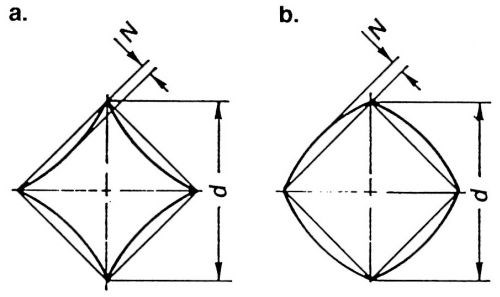
More important is the fact that the stresses in the test piece material at the point of indentation are highly non-uniform because of non-uniform tension distribution across the indentation area. This also results in locally non-uniform elastic deformations subject to recovery after load removal. The resultant permanent indentation is geometrically distorted, compared to the indenter shape. Elastic deformation is greatest under the indenter tip and smallest at the surface of the test piece. The face angle of the indentation is larger than the face angle of the indenter (Fig. 1). This distortion increases as the degree of elastic deformation increases in comparison to the total (plastic and elastic) deformation. Usually a lower modulus of elasticity and a higher elastic limit will yield a higher degree of elastic deformation.

Figure 1 - Schematic of Vickers indentation: (a) for elastic material; (b) for plastic material.
A Vickers indentation is never a perfect negative imprint of the exact indenter geometry, regardless of material properties. The indentation face angle is always distorted by a few degrees1 and is primarily dependent on the elastic properties of the test piece material. The indentation outline is also distorted; it has either a pincushion or barrel shape (Fig. 1) as a result of material sinking or ridging during loading, depending on the degree of plastic flow (cold working) and elastic recovery.
Universal hardness
Universal hardness (HU) is based on indentation with a Vickers indenter and measurement of the indentation depth, or indenter displacement under test load. The designation Universal Hardness has been selected because the method can be applied to all materials. In related literature, other terms referring to this test method, such as HVL or HVT, may also be found. Because the HU test is a different hardness test method, reference to the Vickers method should be avoided to prevent misunderstanding. Also, the indenter has to fulfill requirements different from the classical Vickers test.2 The HU test method itself has been previously described.3 Universal Hardness is defined as the quotient of the test load and the surface area A of the indentation under an applied test load. Based on the pyramid geometry, universal hardness is a function of test load and indentation depth under test load, with the assumption of an indenter of ideal stiffness.

Universal hardness is expressed in N/mm2, which differentiates HU from HV. Because Eq. (2) does not contain a factor to convert the result to kilopounds, values for universal hardness are higher than the classic Vickers hardness numbers by a factor of approximately 10. As a result of the equilibrium between the applied test load and the resistance of the tested material to indenter penetration, universal hardness is also physically more meaningful. It fulfills, contrary to the classic methods, the definition for technical hardness as the resistance of a material to penetration by another object of harder material.
It must also be pointed out that a hardness test method, which is to measure technical hardness according to its true definition, has to be applicable to all materials. If a test method has restrictions in this regard, it is an indication that the test values obtained by the method do not meet the true definition for technical hardness.

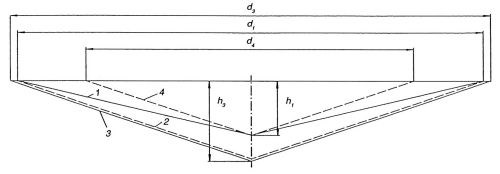
Figure 2 - Schematic representation of Vickers indentation with resulting permanent indentation and Universal Hardness indentation and evaluation.
Relationship between Vickers hardness and Universal hardness
The relationship can be deduced schematically from Fig. 2. The permanent Vickers indentation, which is geometrically distorted, compared to the indenter shape, is represented by outline 1. Its diagonal d, is measured. Using this diagonal, the indentation surface area A, is calculated, based on the wrong assumption of a geometrically correct indenter image. As Fig. 2 shows, a fictitious surface area is actually being calculated and represented by outline 2. The defined surface area A, and the calculated surface area A2 are significantly different for reasons that have been mentioned previously. If, instead of the diagonal d1, the indentation depth h, is measured and used to calculate the Vickers hardness, which would then be based on a geometrically correct indenter image, the result would be based on the fictitious indentation outline represented by line 4.
For determination of the universal hardness, the indentation depth h3 is measured under test load, and the surface area of this indentation is then calculated. In this case, it is irrelevant to the result whether the indentation depth h3, or, as is common with plastics,4 the diagonal is being measured. Based on the Vickers pyramid geometry, the following relationship exists
d3 = 7.008h3, or d3 = 7h3 (3)
Substituting Eq. (3) into Eq. (2) yields:

If we disregard the factor 0.102, which stems from the test load conversion, in the HV equation (1), then from the same indentation, the Vickers hardness is calculated, using the diagonal dv and the universal hardness, using the diagonal d3. The difference, d3 - d1, = Δd, is the degree of elastic recovery of the diagonal after removal of the load. Therefore, the principal difference between universal hardness and Vickers hardness is based on the degree of indentation diagonal elastic recovery Δd. The following possibilities exist:
- For materials exhibiting only plastic flow, d3 = d1, and, therefore, HU = HV.
- In cases where the difference between d3 and d1, lies within the measurement uncertainty of the indenter displacement measurement system, the values for HU and HV will fall approximately in the same range.
- In all other instances (which will be the majority of cases), the universal hardness will be lower than the Vickers hardness. This statement can be proven easily by computing the indentation areas from Eqs. (1) and (2) and substituting d3 = d1 + Δd as the diagonal length for the universal hardness:

In general, universal hardness and Vickers hardness will therefore always be different. The degree of difference depends on the degree of the elastic component of the total indentation deformation. This in turn depends on the modulus of elasticity and the elastic limit of the material to be tested. It is, therefore, impossible to establish a universal conversion formula between Vickers hardness and universal hardness. In reply to the question about the degree of correlation between the Universal Hardness Test and the classical Vickers test for practical applications, the only possibility is to compare empirical test results for a given material and a given material condition. This approach is certainly possible; however, the use of the same indenter geometry with regard to correlation between the test methods will not make this a special case.
Comparison using empirical test results
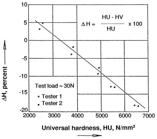
So far, only a very few test method correlation study results have been published. It is necessary to go back to results on steel5 (steel specimens having the same modulus of elasticity), which offer the explanation of another "interfering effect" in the interpretation of the test results (Fig. 3).

Figure 3 - Comparison of Universal and Vickers hardness for steel specimens of different hardness.
With increasing hardness of the specimen, the elastic limit also increases. Therefore, the elastic component of the material displacement during indentation increases as hardness increases. The deviation of universal hardness from Vickers hardness follows the increase of elastic deformation in the manner described. Using a very soft hardness test block, the sign of the reported difference was reversed. This effect can be explained: The indentation is relatively large. The elastic recovery under the indenter tip is only in the range of 10%. This corresponds to a degree of diagonal length elastic recovery that is hardly measurable, given the limit of the diagonal length measurement precision for most instruments on the market.6 In this case, using a very soft hardness test block, a significant amount of material pile-up, or ridging, occurred around the indentation boundary. Because of this ridging, the diagonal length was actually measured outside of the true indentation, resulting in a measurement error of the diagonal length on the long side. The data published as early as 1978 by Dengel and Kroeske confirm these assertions.7
Conclusion
It is generally not possible to establish a direct conversion procedure between Vickers hardness and Universal hardness, even though both test methods make use of the same indenter geometry.
References
1. W. Weiler, Dissertation, Technical University, Braunschweig, 1970.
2. W. Weiler and H-H. Behncke, "Requirements for Indenters in Universal Hardness Testing," (intended for later publication in Materialprüfung).
3. W. Weiler, Materialprüfung, 28 (7/8), 217 (1986).
4. K. Muller, Kunststoffe, 60 (4), 265 (1970).
5. R. Meyer, VDI (Verband Deutsche Ingenieure) Report 583 (1986).
6. W. Weiler, Härteprüfung an Metallen und Kunststoffen (Hardness Testing on Metals and Plastics, 2nd revised and expanded edition), Expert Verlag, Ehningen, Germany, 1989.
7. D. Dengel and E. Kroeske, VDI Report 308 (1978), pp. 63-69.
About the author (written at time of original publication)
The late Prof. Dr.-lng. W. Weiler was, from 1961, active at the Physikalisch-Technischen Bundesanstalt (Federal Institute of Physics and Technology) in Braunschweig, Germany, heading the group "Force" since 1974. He studied mechanical engineering, majoring in material finishing and materials research.
Editor's Note: This is an edited version of a paper presented at SUR/FIN '92, Session F. Peter Raffelsberger made the presentation because of the untimely death of the author.
Related Content
Successful South African Plater Beating the Odds
Remaining focused on quality and reliability, Team Plating Works stays profitable in a volatile and challenging economy.
Read MoreTroubleshooting Alkaline Zinc
One of the most common problems that can arise when plating with alkaline zinc is an imbalance of brightener in the solution. In this helpful Ask the Expert article, Chad Murphy of Columbia Chemical discusses how different zinc metal concentrations and brightener concentrations can impact efficiency.
Read MoreNanotechnology Start-up Develops Gold Plating Replacement
Ag-Nano System LLC introduces a new method of electroplating based on golden silver nanoparticles aimed at replacing gold plating used in electrical circuits.
Read MoreProducts Finishing Reveals 2023 Qualifying Top Shops
Each year PF conducts its Top Shops Benchmarking Survey, offering shops a tool to better understand their overall performance in the industry. The program also recognizes shops that meet a set of criteria to qualify as Top Shops.
Read MoreRead Next
Episode 45: An Interview with Chandler Mancuso, MacDermid Envio Solutions
Chandler Mancuso, technical director with MacDermid Envio discusses updating your wastewater treatment system and implementing materials recycling solutions to increase efficiencies, control costs and reduce environmental impact.
Read MoreEducation Bringing Cleaning to Machining
Debuting new speakers and cleaning technology content during this half-day workshop co-located with IMTS 2024.
Read MoreA ‘Clean’ Agenda Offers Unique Presentations in Chicago
The 2024 Parts Cleaning Conference, co-located with the International Manufacturing Technology Show, includes presentations by several speakers who are new to the conference and topics that have not been covered in past editions of this event.
Read More


