Thermal Energy Deburring Heats Up
The Thermal Energy Method (TEM) for deburring removes thin metal projections (burrs, flash) from manufactured workpieces by using the energy released when combusting fuel gas and oxygen to burn away the undesirable metal. This technology has been in commercial practice since the late 1960s and while still considered a non-traditional finishing process, it has attained wide acceptance in certain industries…
Conventional manufacturing such as machining or casting operations produce burrs or flash that must be removed in a cost-effective manner. Selecting a properly applied deburring method is essential for quality part production. The optimum deburring process can increase productivity, decrease part cost and improve shop through-put. There are numerous ways to remove burrs from a workpiece. The most common is hand finishing, which is tedious, time consuming and produces potentially inconsistent results from part to part. Although the manual process may not be totally eliminated in a manufacturing environment, it most certainly can be reduced by selection of alternative methods. Some of the industry’s more commonly used deburring and finishing methods are listed below:
- Centrifugal barrel
- Vibratory
- Conventional barrel
- Electrolytic
- Thermal energy method
- Centrifugal disk
- Spindle type
- Abrasive flow
- Brush, buffing, polishing
The Thermal Energy Method (TEM) relies on combustion as a source of energy needed for processing. Three essential items are needed to generate this combustion: fuel, oxygen and heat. If one of these components is missing, combustion cannot take place. Likewise, if one of the three is deleted during a combustion cycle, the cycle will process incompletely.
TEM Process Principles
The workpiece to be deburred is placed in a sealed chamber with an index table. There, it is surrounded by a predetermined mixture of gases under pressure. The gaseous mixture is then ignited via an electrical spark creating a burst of intense energy and heat. The combustion generates a 3,315°C (6,000°F) heat wave radiated from the spark affecting all surfaces inside the chamber. After the initial heat wave and the spark has extinguished, the extreme amount of energy that is absorbed into the burr from all sides seeks a path of heat via the main body of the part through the root of the burr. The root of the burr is relatively narrow, which in turn restricts the flow of heat. This restriction causes the heat to build up within the burr until it reaches its automatic ignition temperature. The combustion continues until the flame has reached the surface of the workpiece where the heat is then absorbed into the body, thus quenching the flame (Figure 1).
The burrs having a larger surface-to-mass ratio are raised to a temperature above the material’s melting point and burned with excess oxygen. Through the course of the process, the metal combines with oxygen to form the oxide of the metal that is present in the chamber. This residue settles on the surface of the part as a reddish-brown oxide. Steel parts should be deoxidized before any additional processing takes place. If the oxide needs to be removed, it can be removed by alkaline cleaners, electrolytic cleaning, acid dipping, abrasive jet machining or other mechanical finishing methods. In some cases non-ferrous parts are subsequently treated through further processing such as anodizing, hence, the residue would be removed.
TEM Equipment
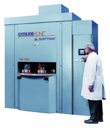
Equipment used in TEM varies in chamber size, price, cycle time and degree of automation. Typical machine constructions consist of a C-frame or post construction, a hydraulic-actuated ram assembly, an indexing table and combustion chamber.
A mechanism actuated by a hydraulic cylinder clamps the chamber closed during pressurization and detonation. The chambers are usually cylindrical and manufactured in various sizes depending upon application. Typical sizes range from 175 mm diameter by 150 mm height to 300 mm diameter by 300 mm in height. The indexing table holds several lower closures and on each closure the operator can place a part(s). The table will index and the closure with the part will be pressed up and sealed beneath the opening in the chamber.
As the need for higher production increases or special part configurations arise, standard equipment may be modified to meet them. Machines are designed with automatic index tables, robotics or pick and place devices incorporated for part processing greater than 200 parts per hour. The number of parts placed in a chamber is directly proportional to the surface area and processing parameters. Therefore, it becomes essential to distribute the quantity of multiple batch loads evenly to ensure uniform processing.
Application Considerations
The thermal energy process primarily uses two parameters to alter the deburring results. The gases when mixed at various ratios provide the flexibility to control the amount of heat generated within the chamber. The second factor is the chamber pressure. Altering the chamber pressure provides process flexibility when processing either larger or small burrs. With these prime process parameters, the process can be regulated to provide various edge radius and deburring results. By varying mixture ratios, the process may be adjusted to accommodate workpiece burr condition.
The successful removal of burrs with changing cross sections is directly related to the gas mixtures and chamber pressure. Large burrs may require a rich mixture combined with high pressure versus smaller burrs, which may need a leaner mixture and low pressure.
The following are other common considerations:
Burr Size: for the purpose of describing relative burr size this article uses the term small (less than 0.0254 mm length) and large (greater than 0.279 mm length). Depending on material and machining procedure burrs can be small, loose and/or comprise resilient prominences. It should be noted that burr properties are inconsistent and do not reproduce evenly time after time. Therefore, maintaining correct chamber pressure and gas mixture is essential to ensure complete removal of burrs that range in size.
Part cleanliness: component cleanliness is the most prevalent problem in the TEM process. Even simple soils or machine ink bluing for scribing can present processing difficulties. Paint, rust, scale, metal cutting fluids, oil and grease have a direct effect on the deburring action. Therefore maintaining a clean part prior to processing is a processing criteria.
Part orientation: two approaches are commonly used. In the first and more practical approach, large quantities of parts are placed in baskets. This method of processing is used for high-production volume. The second approach uses fixtures when part orientation is important. This method prepositions parts uniformly so burrs are pointing in a certain direction each time ensuring proper and effective processing.
Advantages of the Thermal Energy Method
The main advantage of the TEM process is the reduced cost compared to manual finishing methods. The process works very efficiently on virtually any configuration, particularly parts with blind holes or difficult-to-reach intersections. TEM is most effectively used on low carbon and alloy steel components. When batch processing is feasible, hourly production quantities of TEM usually will exceed other deburring processes.
The thermal energy method is a thermal deburring process that is still unique to the industry. Its full potential is unfamiliar to most. The TEM process—if correctly applied—could meet blueprint deburring requirements for internal and external burrs and help to reduce in-process manufacturing operations. The process allows for freedom in both product design and processing methods. TEM offers a deburring capability not matched by any other deburring process available today and will continue to grow and meet the demands of industry.
Kennametal Extrude Hone
Related Content
Practical Environmental Management Reduces Costs, Refines Quality
By focusing on effluent treatment and efficient tin recovery, this Indian surface treatment plant meets stringent environmental standards and sustainable high-quality production.
Read MoreSpatial Coating Thickness Measurement Solution for Prismatic Battery Cells
Coatmaster AG’s 3D noncontact coating thickness measurement system employs ATO technology to provide spatial measurement of coating thickness.
Read MoreOne-Spray EV Battery Coating Provides Water Resistance and Chemicals
AkzoNobel's Resicoat launches one-spray powder coatings technology for EV battery systems, enhancing safety and productivity with high dielectric strength.
Read MoreClean Chemistry for Fuel Cell Technology
Leading efforts to improve hydrogen fuel cell efficiency, this Indiana company has developed chemistry that cleans the inorganic contaminants from inside a vehicle’s radiator. This results in cleaner coolant and a more efficiently run hydrogen fuel cell.
Read MoreRead Next
Education Bringing Cleaning to Machining
Debuting new speakers and cleaning technology content during this half-day workshop co-located with IMTS 2024.
Read MoreDelivering Increased Benefits to Greenhouse Films
Baystar's Borstar technology is helping customers deliver better, more reliable production methods to greenhouse agriculture.
Read MoreEpisode 45: An Interview with Chandler Mancuso, MacDermid Envio Solutions
Chandler Mancuso, technical director with MacDermid Envio discusses updating your wastewater treatment system and implementing materials recycling solutions to increase efficiencies, control costs and reduce environmental impact.
Read More


.jpg;maxWidth=300;quality=90)


