Best Plating Practices for the Application of Brush Plated Zinc-Nickel
Brush plating is an industrial electroplating process designed for demanding OEM and repair applications, without the use of an immersion tank. This presentation demonstrates the best practices for brush plating zinc-nickel to meet the ASTM standards of hydrogen embrittlement and corrosion protection. From preparatory steps to the application of a trivalent chromium conversion coating, the proper plating techniques needed to meet the customers’ demanding requirements are discussed.
Editor’s Note: The following is a paper based on a presentation given at NASF SUR/FIN 2019, in Rosemont, Illinois on June 5, 2019 in Session 13, Zinc Alloy Finishing Trends: Challenges & Prospects. A pdf of this paper can be accessed and printed HERE; the complete Powerpoint presentation is available by clicking HERE.
Abstract: Brush plating is an industrial electroplating process designed for demanding OEM and repair applications, without the use of an immersion tank. Many of today’s applications require well-engineered and proven deposits that pose as little risk as possible to both the operator and the environment. For the aerospace industry, zinc-nickel is a less toxic alternative to cadmium that can be used to repair damaged cadmium, zinc-nickel and IVD aluminum on high strength steels. It also meets the performance requirements of AMS 2451/9 and BAC 5664. What’s more, zinc-nickel does not require a post-plating, hydrogen embrittlement relief bake and can provide excellent corrosion protection - when properly applied. This presentation will demonstrate the best practices for brush plating zinc-nickel to meet the ASTM F519 standard of hydrogen embrittlement and corrosion protection. From preparatory steps to the application of a trivalent chromium conversion coating, the proper plating techniques needed to meet the customers’ demanding requirements are discussed.
Introduction and background: Selective plating was originally developed in 1938 in Paris, France by George Icxi. It evolved from the simple touch-up of tank plated parts. In 1959, the Steel Improvement and Forge Company (also known as Sifco Industries) bought a Canadian-based firm and moved all operations to Cleveland, Ohio. In 2012, Sifco ASC was acquired by Norman Hay, headquartered in the UK. NH was originally founded in 1940 doing chromium plating and hard anodizing. Norman Hay was acquired by Quaker Houghton in October 2019.
For the aerospace industry, zinc-nickel is a less toxic alternative to cadmium that can be used to repair damaged cadmium, zinc-nickel and IVD aluminum on high strength steels. It meets the performance requirements of AMS 2451/9 and BAC 5664, requires no post-plating or hydrogen embrittlement relief bake, and can provide excellent corrosion protection when properly applied. This paper presents the best practices for brush plating zinc-nickel to meet the ASTM F519 standard of hydrogen embrittlement and the ASTM B117 standard of corrosion protection. A proprietary Zn-Ni process providing low hydrogen embrittlement (LHE) during brush plating is used in this study.*** From preparatory steps to the application of a trivalent chromium conversion coating, the proper plating techniques needed to meet the customers’ demanding requirements are discussed.
Selective plating concepts
Selective plating, or more commonly brush plating, is a portable process for plating localized areas on a workpiece without the use of an immersion tank. There are four key elements to a brush plating set-up, shown in Fig. 1:
- The workpiece, in this case is the inner diameter of a cylinder that is being rotated by a turning head fixture on the right.
- The power pack, with current, voltage and amp-hr control, on the left.
- The plating tools, the anode here inserted into the hole in the workpiece, and
- The preparatory and plating solutions, contained in the tank in the solution flow system, center.
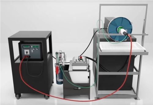
Figure 1 - Typical setup for selective / brush plating.
The anodes can consist of graphite, Dura-A-Form, platinum, or platinum-clad niobium or titanium. They are typically made to conform to the substrate to optimize thickness distribution. The red and black cables connect the power source to the anode and workpiece, and the green and black tubing provide solution circulation between reservoir and workpiece.
The rest of operation decisions are based on if the plating solutions need to be heated, flowed, or dipped, how the workpiece is to be masked to isolate the selected area, and whether any auxiliary equipment is needed to hold or rotate the part and/or or the plating tools.

Figure 2 - Selective plating operation.
As shown in Fig. 2, an electrolyte containing metal ions is introduced between a positively-charged anode (i.e., the preparatory or plating tool) and a negatively-charged cathode, (i.e., the workpiece). The anode itself is wrapped with a material that can be made of cotton, PermaWrap, red or white TuffWrap, etc. The wrap serves two main functions: to prevent an anode to cathode short-circuit and to act as the carrier for the solution which helps facilitate the current flow by wetting both electrodes to create the electrochemical cell. The solution can be introduced to the workpiece by flowing the solution through the anode using an external pump or by dip plating, where the anode is dipped into a beaker sitting near the workpiece.
A typical plating scheme consists of several preparatory steps that prepare the surface for the final metal deposition step. Each prep step requires a dedicated anode. The prep steps usually entail electroclean, etch, desmut and activation of the surface of the workpiece. The part is rinsed in between steps with DI water to avoid cross contamination and assure a clean work surface. After the workpiece has been properly prepared, a nickel preplate can applied and is substrate dependent.
Evaluation methodology
Hydrogen embrittlement
The primary test method for evaluating hydrogen embrittlement is ASTM F519, which describes mechanical test methods and defines acceptance criteria for coating and plating processes that can cause hydrogen embrittlement in steels.† Specimens, as shown in Fig. 3 (Types 1.a1 and 1.a2 shown), are plated in accordance with the specification and maintained under sustained load in air to measure the time to rupture or completion of the test period. The entire notch and 0.5” on either side must be plated.
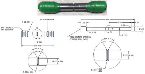
Figure 3- Layout of specimens used in hydrogen embrittlement testing of steels: (L)Type1.a1 and (R) 1.a2 notched bars.
Samples may be loaded individually or by multiples in a series. There is a minimum of four specimens used in each test. The samples undergo a sustained load which is maintained for a minimum of 200 hr at 75% of the tensile notched fracture strength (NFS).
In the event of one or more specimen fractures, those specimen(s) are removed and replaced with dummies and placed back under load. The total time off-load cannot exceed 10% of total test duration, and additional time in excess of 10% is added to the test. Fracture at any location other than the notch invalidates the test, and replacement testing may occur for all four specimens.
If there is no fracture, the plating process is non-embrittling. If one of the four fracture, the remaining three specimens may be step loaded every 2 hr in 5% increments to 90% of the NFS after completing the 200-hr sustained load. The process is considered non-embrittling, if the specimens survive 2 hr at 90% NFS. If two or more fracture, the plating process is considered to be embrittling.
Corrosion
Corrosion is evaluated according to ASTM B117, which describes the apparatus, procedure and conditions to create and maintain the salt spray test environment.†† The apparatus consists of a fog chamber, a salt solution reservoir, compressed air, an atomizing nozzle, specimen supports, chamber heating and a means of control of the salt spray environment. Test specimens are positioned 15-30º from vertical in the chamber, with no metal contact and unencumbered exposure to the salt fog. The salt solution consists of 5% sodium chloride in Type IV water and is atomized at 35 ± 2°C at pH 6.5-7.2. A minimum of two clean fog collectors are placed in the chamber. A collection rate of 1.0-2.0 mL/hr is specified. Testing is continuous, and the chamber can only be opened once daily for inspection of the samples.
Process and properties
There are two process/property specifications germane to this work. Boeing BAC 5664 outlines the “requirements for materials and procedures for deposition of ZnNi plating on low-alloy steel using the stylus electroplating process.” AMS 2451††† covers the “engineering requirements and process for brush plating of zinc-nickel by electrodeposition.” It is used, in conjunction with AMS 2451/9, for corrosion-protective, zinc-nickel deposits, which may allow omission of hydrogen embrittlement relief treatment of high-strength steel. The requirements of the two specifications are compared in Fig. 4.
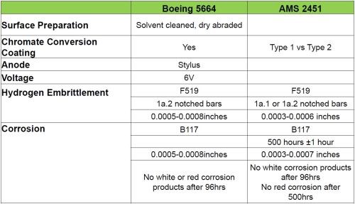
Figure 4 - Comparison of Boeing 5664 and AMS 2451 specifications.
In BAC 5664, the anode may consist of graphite of high purity and density, or dimensionally-stable (DSA) platinum, platinum-iridium, platinum-plated titanium or platinum-plated niobium. Cotton batting and cotton or Dacron sleeving is specified. The maximum area of the ZnNi stylus plating is 5 in2, and the minimum thickness is 0.0005 in. During plating, the ZnNi is not pre-wetted and the electrolyte may be applied with a squeeze bottle or dip method. Stylus anode should be flush with the area being plated during operation and use a reciprocating back-and-forth or circular motion.
AMS 2451 covers the use of a chromate conversion coating. Types 1 and 2 designate respectively, (1) no chromate coating and (2) a chromate coating applied via a brush, spray or dip process. Further, grades A and B, designate a hexavalent or trivalent chromate process, respectively. The zinc-nickel composition range is 6 to 20% nickel, plated to a thickness of 0.0004 to 0.0007 in. Salt spray exposure time is 500 ± 1 hr, per ASTM B117. For a Type 1 finish, there should be no evidence of red corrosion after 500 hr. Type 2 should exhibit no evidence of white corrosion products after 96 hr and no evidence of red corrosion after 500 hr.
Hydrogen embrittlement study
The goal of this portion of the study was for the Zn-Ni LHE coating to pass hydrogen embrittlement testing within 24 hr after plating on 1a.1 and 1a.2 bars with no post-deposition bake for hydrogen embrittlement relief. Even with the use of a “low hydrogen embrittlement” process, an amount of hydrogen is present in the deposit, albeit much reduced. Over time under ambient conditions after plating, a portion of the hydrogen will be released. The longer the time between plating, the lower the residual hydrogen. Production efficiencies are improved if this “relief” time can be reduced to 24 hr, while still passing the embrittlement test.
Specimen preparation was as follows:
- Clean and degrease notch bars with acetone.
- Mask bar threads and radial areas with tape and sandblast with 120 grit silicon carbide.
- Remove masking, rinse with DI water and clean with acetone using lint free wipe.
- Mask bar threads and radial areas with tape, thread the notch bar into a barrel fixture and insert into the turning head.
- Set bar rotation speed at 60-65 RPM.
- Plate Zn-Ni LHE with no pre-wet, then rinse with DI water.
- Immerse in trivalent chromium conversion coating for 90 sec, rinse with DI water and dry with compressed air. No bake required.
The operational configuration is shown in Fig. 5.
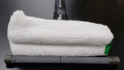
Figure 5 - Zn-Ni brush plating configuration.
The experimental design involved the effect of a number of variables on hydrogen embrittlement performance. Constant current densities of 3 and 6 A/in2 were compared, along with a constant voltage of 6V. An anode conforming to the curvature of the test bar, with 50% effective electrical contact, was compared to the stylus type of anode, with 25% effective contact. The anode materials, graphite and DSA, were also compared. The tests were conducted in three phases, each one more stringent than the last. The goal of Phase 1 was to pass hydrogen embrittlement testing within 72 hr or less after plating at 3 and 6 A/in2. Phase 2 was intended to pass within (a) 48 hr and (b) 24 hr after plating at 6V (as per BAC 5664) and 6 A/in2. Phase 3 sought to pass in under 24 hr after plating at 6 A/in2.
Phase 1
Phase 1 compared post-plating times to test: ≤72 hr and approximately one week. In addition to the 3 and 6 A/in2 current density comparison, two test bar configurations (1.a1 and 1.a2) were compared. The effect of full and partial plating of the test bar was also explored, with samples prepared both fully plated from end to end and with plating only within ½” of the notch. All samples were plated with a 50% contact conforming, graphite anode. The results in Fig. 6 indicate that all samples passed ASTM F519.
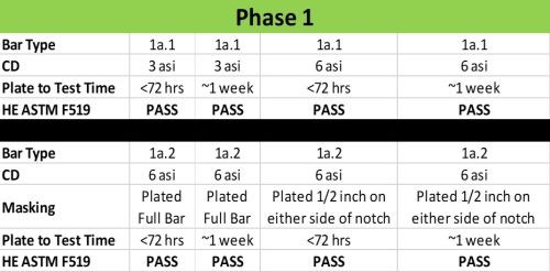
Figure 6 - HE Phase 1 results per ASTM F519.
Phase 2
Given the results of Phase 1, the next phase was more stringent to decrease total process time. The plate-to-test times were shortened to 24 and 48 hr. The higher constant current density of 6 A/in2 was compared to a constant voltage of 6V (BAC 5664). Comparison of the two test bars and the two types of anode geometries was continued into this test. The 1a.2 bars were plated along the full length. All samples were plated with a graphite anode.
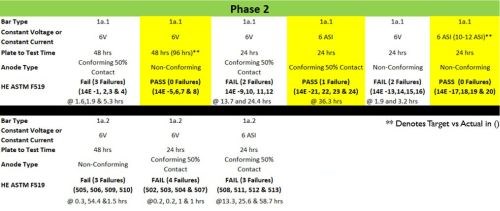
Figure 7 - HE Phase 2 results per ASTM F519.
The results are shown in Fig. 7, where the yellow highlighted conditions were found to pass ASTM F519. It can be seen that only three of the nine groupings passed. Of the three, only one was plated as planned (conforming anode at 6 A/in2). One (non-conforming stylus anode used at 6V) was delayed for 96 hr between plating and HE testing. The other (non-conforming stylus anode used at 6 A/in2) was plated at a higher current density (10-12 A/in2). It is notable that the 1a.2 test bars all showed failure with the shortened plate-to-test times.
Phase 3
Phase 3 took the results of the two previous experiments, optimizing conditions to reach the target of a 24-hr plate-to-test interval. With the shortest interval studied, comparisons were made of the anode material (DSA versus graphite) and the anode geometry (conforming with 50% contact area and the stylus). Additional variables were introduced, including the use of a neutral nickel strike prior to Zn-Ni LHE plating, a 20-V Zn-Ni strike prior to Zn-Ni LHE, and heating the of Zn-Ni LHE solution during plating. All specimens were plated at 6 A/in2.
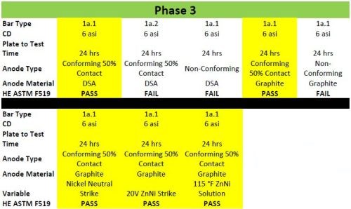
Figure 8 - HE Phase 3 results per ASTM F519.
The results are shown in Fig. 8, where the yellow highlighted conditions passed ASTM F519. Here, five of eight groups passed. These groups all utilized the conforming anode geometry. Both DSA and graphite anodes met the standard with the conforming geometry at the CD of 6 A/in2 with the 24-hr waiting period. The three new variables with conforming graphite anodes and a current density of 6 A/in2 were successful. Again, using the 1.a1 test bars were superior to 1.a2 test bars, possibly related to geometric factors.
In summary, selectively plating Zn-Ni LHE can meet the requirements of ASTM F519 within 24 hr after plating under the following conditions:
- Use of 1.a1 test bars
- Conforming anodes of either DSA or graphite
- 6 A/in2 current density
- Neutral nickel strike
- High voltage Zn-Ni strike
- Heated Zn-Ni LHE solution
Corrosion performance
The goal of the corrosion testing of Zn-Ni LHE was to pass the requirements of AMS 2451, i.e., no red corrosion at 500 hr for the plated coating without a conversion coating, and no white corrosion at 96 hr / no red corrosion at 500 hr with the conversion coating. The testing followed ASTM B117. Plate thickness was set at 0.00065 in. The following evaluation and comparisons were undertaken:
- BAC 5664 process with Zn-Ni LHE
- Cotton wrap vs. White Tuff Wrap vs. Red Tuff Wrap
- Dip plating vs. flow plating
- No conversion coating vs. trivalent vs. hexavalent coatings
- Dip vs. squirt conversion coating application
- Constant voltage vs. constant current (6 A/in2 vs. 6V)
All photos of the salt spray results to follow show specimens that were rinsed with DI water, dried, then photographed. The dried surface is a more accurate representation of the severity of the corrosion result.
BAC 5664 process with Zn-Ni LHE
Specimens were prepared via BAC 5664. A stylus-type of graphite anode was used and a constant voltage of 6V was applied throughout the plating cycle. The minimum thickness was 0.0005 in. A trivalent conversion coating was applied after plating. Two methods of applying the conversion coating were compared: (a) immersion (dipping in a beaker containing the solution) and (b) squirting the coating solution of the surface from a squeeze bottle alternating 5 seconds of squirt and 15 seconds off until 90 seconds was reached. The results are shown in Fig. 9.
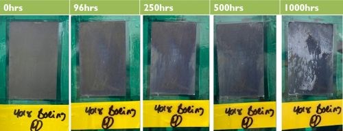
(a) Trivalent conversion coating applied by a 90-sec dip.
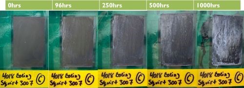
(b) Trivalent conversion coating applied by a 90-sec squirt/spray application.
Figure 9 - ASTM B117 corrosion test results for Zn-Ni LHE samples plated according to BAC 5664: (a) immersion and (b) sprayed trivalent conversion coating; Zn-Ni plating at a constant voltage of 6V, solution at room temperature; target thickness of 0.00065 in.
The dipped trivalent conversion coating produced slightly better results as compared to the squirted/sprayed trivalent conversion coating. All samples passed AMS 2451 - Type 2. A slight blushing was observed but no white corrosion at 96 hr and no red corrosion at 500 hr were observed. The average alloy composition with the BAC 5664 process was 8.8% Ni, with the balance zinc.
Traditional plating with Zn-Ni LHE
The next phase of the study dealt with traditional “dip” plating of Zn-Ni LHE, where the anode is repeatedly dipped into a beaker of solution every 5 seconds to ensure enough solution is present at the surface of the workpiece. A cotton wrap was used on the anode and a current density of 6 A/in2 was applied. The objective was to compare corrosion results for plated Zn-Ni LHE (a) with no conversion coating, (b) with a trivalent conversion coating and (c) with a hexavalent conversion coating. The conversion coating was applied with the squirt/spray method for 90 sec followed by a rinse and air dry. In the case of the hexavalent conversion process, the solution was heated to 95-100°F during application. The target thickness was 0.00065 in. These results would be compared with specimens plated with a brush or flow-plated regimen.
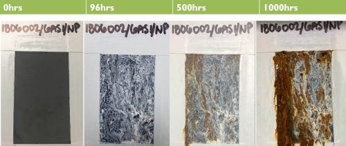
(a) No conversion coating.
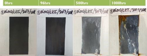
(b) Trivalent conversion coating.
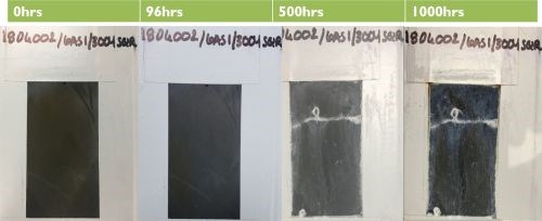
(c) Hexavalent conversion coating.
Figure 10 - Comparison of ASTM B117 corrosion performance for traditional dip plated Zn-Ni LHE: (a) with no conversion coating, (b) with a trivalent conversion coating and (c) with a hexavalent conversion coating.
The results are shown in Fig. 10. Both conversion coatings passed AMS 2451, with no white corrosion after 96 hr, and no red corrosion after 500 hr of ASTM B117 salt spray exposure. Specimens with no conversion coating failed AMS 2451, with red corrosion visible between 100 and 230 hr.
The nickel content in these samples plated at 6 A/in2 averaged 11.5%, higher than the 8.8% value produced at a constant 6V per BAC 5664.
Flow (brush) plating with Zn-Ni LHE
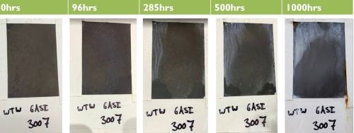
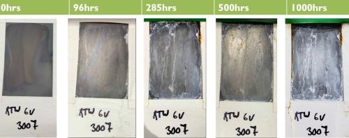
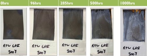
The next phase of study examined flow (brush) plating, where the solution was pumped through the anode for a constant supply at the work surface, with the goal of comparing the anode wrap and the question of constant voltage versus constant current density addressed in the previous phases of work. The anode wrap compared corrosion results for cotton, White Tuff and Red Tuff wraps. Results for the BAC 5664 constant 6V were compared with those for 6 A/in2. The target thickness was 0.00065 in. The trivalent conversion coating was used for all conditions, with the solution applied by a 90-sec squirt/spray application. The results are shown in Fig. 11.
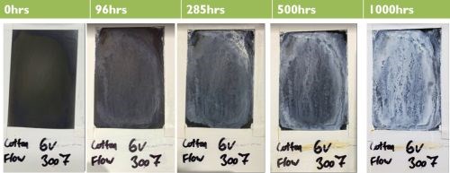
(a) Cotton wrap with Tri Cr; 6V.
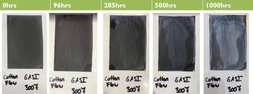
(b) Cotton wrap with Tri Cr; 6 A/in2.
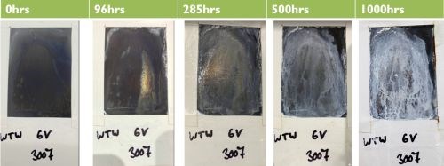
(c) White Tuff wrap with Tri Cr; 6V.
(d) White Tuff wrap with Tri Cr; 6 A/in2.
(e) Red Tuff wrap with Tri Cr; 6V.
(f) Red Tuff wrap with Tri Cr; 6 A/in2.
Figure 11 - ASTM B117 corrosion test results for flow (brush) plated Zn-Ni LHE with a trivalent Cr conversion coating: comparison of cotton, White Tuff and Red Tuff anode wrap materials (top to bottom pairs); comparison of constant voltage (6V)(a, c, e) versus constant current density (6 A/in2)(b, d, f).
In general, the panels plated at a constant 6 A/in2 performed better than those plated at a constant 6V.
Comparing with the traditional plating results of Fig. 10, cotton wrap, white tuff wrap, and red tuff wrap all performed better than traditional dip plating at 250, 500 and 1000 hr of salt spray.
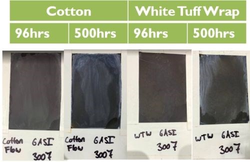
Figure 12- Best results from ASTM B117 testing.
Analyzing all panels, the best corrosion results (Fig. 12) were obtained with flow (brush) plating at a constant current density of 6 A/in2, using cotton or White Tuff Wrap anode materials.
Future work
Future work with hydrogen embrittlement performance will focus on the inferior performance observed with the 1.a2 notched bars, including the those added processes that worked with 1.a1 bars: the neutral nickel strike, 20V Zn-Ni strike, and heating the Zn-Ni plating solution. Corrosion work will include studies of alternatives to the trivalent chromium conversion process. Studies on the lifetime of the Zn-Ni solution and how well it performs over the long term are planned.
Acknowledgements: The authors are indebted to the efforts of Teri Zarnesky, Lab Technician, Derek Vanek, Technical Manager, Derek Kilgore, Design and Project Engineer, Ken Mabe, Solution Manufacturing Technician, Mike Torma, Solution Manufacturing Technician and Jeff McArthur, Technical Service Representative.
About the authors
Sarah Medeiros works as a Corrosion Engineer at Sifco ASC. She graduated from the University of Akron with a Bachelor of Science in Corrosion Engineering. Prior to joining Sifco ASC in 2018, Sarah had several co-op rotations at The Lubrizol Corporation working with rust preventives, corrosion inhibitors, and organic coatings and resins with experience in corrosion test methods.
Danijela Milosevic-Popovich, R&D Manager at Sifco ASC, joined the company in 2005. She is responsible for the design and execution of lab programs to develop and evaluate current products, new products and plating applications. She also provides the technical support and assistance to the quality, contract service and solutions manufacturing groups. She graduated from the State University of New York at Buffalo with a Bachelor of Science and Master of Engineering in chemical engineering. She then continued to earn her Master of Engineering Management from Ohio University. Prior to joining Sifco ASC, she worked in the semiconductor (IBM) and rubber industries.
*Compiled by Dr. James H. Lindsay, Technical Editor - NASF
** Corresponding authors:
|
Sarah Medeiros Corrosion Engineer Sifco ASC 5708 E. Schaaf Road Independence, Ohio 44131 Phone: (216) 524-0099 E-mail: smedeiros@sifcoasc.com |
Danijela Milosevic-Popovich R&D Manager Sifco ASC 5708 E. Schaaf Road Independence, Ohio 44131 Phone: (216) 750-2237 E-mail: dmilosevic@sifcoasc.com |
*** Zinc-Nickel LHE® 4018/5970, Sifco ASC, Independence, Ohio, USA
† ASTM F519-18, Standard Test Method for Mechanical Hydrogen Embrittlement Evaluation of Plating/Coating Processes and Service Environments, ASTM International, West Conshohocken, PA, 2018, http://www.astm.org/cgi-bin/resolver.cgi?F519.
†† ASTM B117-18, Standard Practice for Operating Salt Spray (Fog) Apparatus, ASTM International, West Conshohocken, PA, 2018, http://www.astm.org/cgi-bin/resolver.cgi?B117.
††† AMS 2451, Plating, Brush General Requirements; AMS 2451/9C, Plating, Brush, Zinc-Nickel Low Hydrogen Embrittlement, SAE International, Warrendale, PA, 2019: https://www.sae.org/standards/content/ams2451; 2018: https://www.sae.org/standards/content/ams2451/9/.
Related Content
ASTM Committee Honors ChemQuest Vice Presidents
Two ChemQuest vice presidents are being recognized by ASTM Committee D01 on paint and related coatings, materials and applications.
Read MoreReducing VOCs
Coating materials (paint and solvent) are one of the most significant sources of VOC generation. John Owed of Carlisle Fluid Technologies offers advice for reducing VOC consumption.
Read MoreBisphenol-Free Coating for Beverage Can Ends
A BPA-NI internal coating for beverage can ends from AkzoNobel complies with FDA and EU regulations.
Read MoreAdditive Portfolio Eliminates PFAS Substances
By going PFAS-free, Clariant offers sustainable additive solutions for powder coaters that meet global environmental standards and regulatory requirements.
Read MoreRead Next
Episode 45: An Interview with Chandler Mancuso, MacDermid Envio Solutions
Chandler Mancuso, technical director with MacDermid Envio discusses updating your wastewater treatment system and implementing materials recycling solutions to increase efficiencies, control costs and reduce environmental impact.
Read MoreA ‘Clean’ Agenda Offers Unique Presentations in Chicago
The 2024 Parts Cleaning Conference, co-located with the International Manufacturing Technology Show, includes presentations by several speakers who are new to the conference and topics that have not been covered in past editions of this event.
Read MoreEducation Bringing Cleaning to Machining
Debuting new speakers and cleaning technology content during this half-day workshop co-located with IMTS 2024.
Read More




.jpg;maxWidth=300;quality=90)

