Mechanical finishers have been taught—whether through passed-down knowledge, schooling or hard-earned experience—that “surface foot per minute” (SFPM) is the rule of thumb in finishing.
While SFPM is a good starting point, however, it shouldn’t be thought of as the end-all for your finishing processes. It is another variable within the process that needs to be defined and monitored, but it should not be the one variable from which all others become defined.
When we look at mechanical finishing, the first and most important items that should be considered are the shape and type of part. From this, buff and compound choices can be made, and process parameters determined.
Advancements in buffing wheels, compounds and equipment allow us an increasing variety of process options. Using these tools to your advantage can put the benefits of quality improvement, increased productivity and cost savings at your fingertips.
Build by Shape, Size
The following project is an example that followed the mindset of building a process around the part shape and type, not just by the chart-recommended SFPM for the metal type.
A large-volume finishing company that manufactures stamped 301 stainless steel automotive parts was challenged to buff a product it had been working with for more than 30 years with one small difference: the product was no longer two-dimensional. Instead it was three-dimensional and required a buffed finish in openings that were 1.5 and 2 inches below the primary surface and at angles of 90 and 75 percent.
This contract had eluded the company for five years, as it could not find the proper process to sufficiently buff those deep areas. It tried its existing process for standard production parts, which used medium-diameter buffs running at the industry standard of 1,750 rpm. For heavy cuts, treated cloth and sisal buffs stacked without spacing were used. Mill-treated cotton buffs stacked without spacing were used for the cut and color motions, and the final color head used 86/80 untreated color buffs and was also stacked without spacing.
The use of medium- and finer-grade cut and color compounds for the final coloring heads also were a staple in the process. The spindle rotation of the part was in the 50-rpm range, which had been determined over many years to be the optimum speed for buffing on the flat part shape, and for finish and cycle time requirements.
Changing the Process
The combination of buff size and rpm resulted in SFPM of about 7,000, which is about 2,000 below the charted recommendation for stainless steel of 9,000-10,000 SFPM. However, this was the maximum SFPM that could be achieved due to the limitations of buff size to accommodate the size of part and the limited ability to change equipment speed.
While this process produced acceptable results on all of the standard, 2D parts, it was never successful in finishing the 3D parts. To solve this problem, the company changed every facet of its existing process.
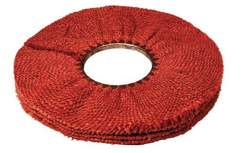
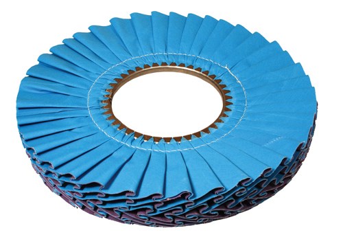
It first increased the buff diameter by 22 percent while keeping the inside diameter the same, resulting in an increased amount of usable material that could reach deep into the part. The buff constructions and material types remained the same or similar, but the dip treatments were changed to increase the flexibility and the cut rate.
Next, the company had to identify which heads would buff which areas of the recessed openings. The buff heads then were built with spacing to open up the head and create flexibility to maneuver around the recessed areas. The number of buffs per head was also reduced to narrow the head enough to enable the buffs to fit into the openings.
In addition, the heads were realigned so that the buffs had optimum access within the opening. One constant was the compound selection. Because the metal was very good quality, it was determined that the existing compound selections would be adequate. If the metal was stretched or pitted, a more aggressive cut and color compound would have been selected.
A major change in the process was a reduction in the speed of both the buffs and the part spindle. This was required to give the buff enough time to access the opening and sufficiently buff the deep recessed areas.
If either the buff speed or the part spindle speed were too high, an over-buff condition would form on the high flats and corners, while the lowest areas of the deep recesses would not be finished. Because this is a stamped stainless steel part of a moderately thin gauge, the corners are vulnerable to buff cut-through.
So, the speed was reduced by as much as 65 percent on the buffs and by almost 80 percent on the spindle, resulting in an SFPM of less than 3,000—much lower than the original targeted SFPM of 7,000 and the 9,000-10,000 that is chart-recommended.
Reduced Cycle Time
Due to the shape and size of the part, production requirements, equipment type and availability, and the targeted cost per piece, the customer expected a cycle time of between 45 and 60 sec. The final, amended process produced a cycle time of 50 sec. The cost per piece was also right on the mark. Buffs and compounds make up the greatest portion of that cost per piece, and, by reducing the number of buffs per head and adding spacing, setup costs were lower than originally expected.
The increased buff diameter and slow SFPM also resulted in reduced wear on the buffs and increased buff life. In addition, compound usage was reduced as it was only needed for cut and not for cooling as it is with the high-SFPM process.
This project resulted in the company receiving a contract for this part of $2-3 million annually and additional RFQs from existing customers on similar parts.
The lessons learned can be summarized as: look to new products, try new ideas and don’t be afraid to stray from the “rules of finishing” to meet your requirements. The unconventional may actually be just what your business needs.n
Bob Pinchot is the field applications manager for Osborn. For more information, please visit Osborn.com or call 800-720-3358.
Osborn/JacksonLea


