Calculating Applied Media Force During Vibratory Finishing
Establishing optimum operational characteristics for finishing a specific part.
Despite attempts to equilibrate vibratory variables, what appear to be identically set-up vibratory bowls will finish identical loads of parts in different times. This article explores the cause along with techniques to capture non-apparent operational characteristics, and a formula to calculate the applied media force to the average surface area of a part.
Applied media force is partially predicted by Newton’s Second Law, F = ma, where “m” is the mass and “a” is acceleration. I will consider m as the media weight above a part at bowl mid-channel and as the velocity of the media. F = ma will then be incorporated into a new Media Contact Formula (MCF). When measurable process variables are inserted into the MCF, a better understanding of efficiency differences between seemingly identically operating vibratory bowls can be calculated.
What is Mass?
The mass weight in pounds of the media column above the part at bowl mid-channel is affected by the available depth of the vibe bowl channel, attrition-induced media depth reduction and weight density of the media composition. All vibratory media are affected by attrition, which is simply weight mass lost to frictional abrasion. Each piece of media decreases in volume every hour it is run. Media attrition is most noticeable as a decrease in the media height in the channel over time.
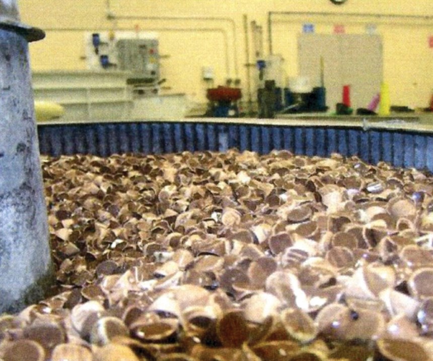
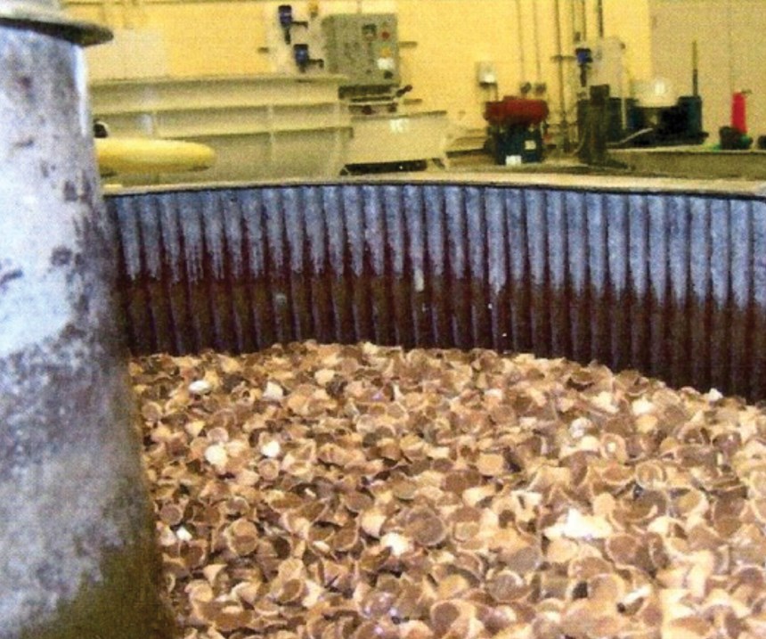
As volume decreases, so too does the mass weight above the part at bowl mid-channel (see images at the top). The first photo shows a 10-inch vibratory bowl channel properly loaded to its full available depth of 10 inches. This optimizes this machine’s performance as related to media volume. The second photo shows the same vibe bowl affected by attrition over time. Now, media depth is just 6 inches, as 4 inches (approximately 40 percent of media volume) have been lost to attrition. If the reduced poundage of media in the bottom photo is entered into the formula F = ma, the amount of force F that media can apply is also reduced. Less force means more time required to accomplish the same amount of work.
Mass Rolling Velocity
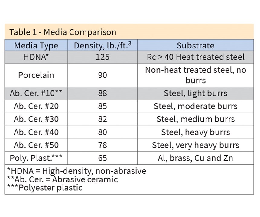
The media composition used depends on the part’s finish and the speed with which it is performed (see Table 1).
Mass rolling velocity can be measured as the distance a part travels per minute of time. The further the distance traveled per minute, the more work done in that minute because the part is contacted by the media more often.
Mass movement in the vibratory bowl undergoes two simultaneous planes of motion: vertical roll and horizontal slide. Vertical roll is the circumference of the circle formed where the width of the channel is the circle diameter. A vibe bowl channel properly loaded will generate maximum circumference. When media level is low due to attrition, the circle diameter is smaller, its resulting circumference is shorter and so too is the mass rolling distance.
Calculating mass velocity. Let’s assume that in 60 seconds, a part rolls four times and makes one lap around a bowl with a roll circle circumference of 78.5 inches and lap circumference of 157 inches. We can calculate velocity per minute as follows:
- Vertical = 4 × 78.5 in. = 314 in.
- Horizontal = 1 × 157 in. = +157 in.
- Distance in 60 sec. (1 min.) = 471 in.
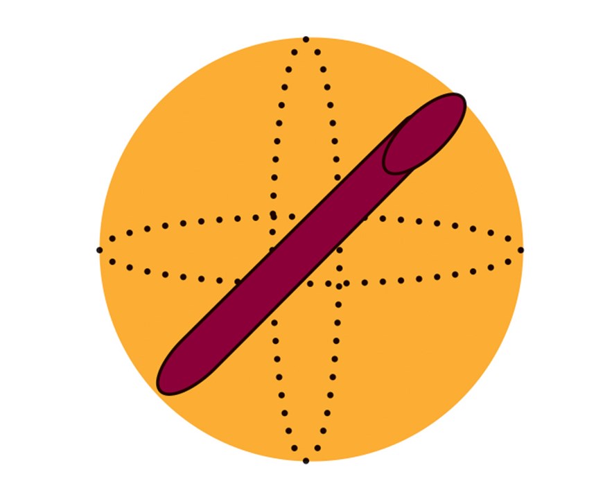
Projecting part contact area. Parts roll orthographically during vibratory processing. Regardless of a part’s size and shape, it will rotate about its x, y and z axes within a spherical volume inscribed by its longest dimension. At any one moment in time, part rotation, relative to its x, y or z axes, is random and indiscriminate. We can assume, however, that for the overall duration of the processing cycle, the exposure of the part’s x, y and z axes to the media mass will be uniform.
Since force is applied to an area, the question arises: What one area of the part is being contacted at any moment in time? This is an unknown entity as we can’t see the momentary alignment of the part within the media mass, therefore the area being contacted is an indeterminate variable. We can determine, however, a part’s average area.
Average Part Area
Assume the red cylinder in Diagram 1 to be a part 8 inches in length, 1 inch in width and 2 inches in height. Its average area can be determined by the volumetric dimensions from the smallest box, which envelops it as follows:
Average Part Area Calculation
- Average length 1; x axis area = 1 in. × 8 in. = 8 in.²
- Average length 2; x axis area = 2 in. × 8 in. = 16 in.²
- Sum of length areas = Side 1 × 2 + Side 2 × 2 = 48 in.²
- 1. Average length area = 48 in.² ÷ 4 x axes = 12 in.²
- 2. Average end 1; y axis area = 1 in. × 2 in. = 2 in.²
- 3. Average end 2; z axis area = 2 in. × 1 in. = + 2 in.²
- Total of Average x + y + z areas = 16 in.²
- 4. Average Part Area = 16 in.² ÷ 3 axes = 5.33 in.²
Therefore, on average, 5.33 inches of the part are being forcefully contacted by media at any one moment in time. Using the smallest rectangular box volume technique, the average surface area of any part being processed can be determined.
Average surface area assumptions: Two assumptions must be made for the average area calculation. Assumption 1: An ornately shaped part will have an exact area smaller than the cross-sectional area of the box within which it can be contained. True as this is, using the smallest rectangular box volume will allow for comparison of identical side-by-side machines, running identical parts; and Assumption 2: the volume of the box enveloping the part has four-each, x-axis or length sides. By taking the average length area of the sum of the four x-axis sides we can determine the average length area exposed to the media when the part is in the x-axis orientation.
Effect of Centrifugal Force: Centrifugal force via centrifugal barrel and centrifugal disc machines reduce process time, and such equipment is common in finishing departments. The formula for centrifugal force is F = mv²/r. In considering the gravitational force on the average surface area of the part by the column of media above it, and combining centrifugal force formula with the traditional force formula of F = ma, we can generate the new Media Contact Force (MCF) formula MCF = (m/g)(v²/r). Where m = lb. of media in the column above the average part area; g = the gravitational constant, 32 ft./sec.²; v = part velocity in ft./sec.; and r = radius of the media mass present.
Determining MCF Variables
Determining the m = mass of media variable: Let’s use the density of HDNA media as found in Table 1, the average part area of the part as described earlier, and a vibe bowl with a channel containing, when properly loaded, 25 inches of media. The media applies a force equal to the weight in pounds of the column of media above the average surface area of the part. For this and all subsequent calculations, using the MCF, it’s assumed that the part is centered at the base of the bowl’s channel. To determine the weight in pounds of the media column above the average part surface area:
- From Table 1: 1 ft.³ HDNA = 125 lb./ft.³
- Average area of the part = 5.33 in.²
- Volume of column of media above the average part area: a. 5.33 in.² × 25 in. = 133.25 in.³ ÷ 1,728 in.³/ft.³ = 0.077 ft.³
- lb. mass = 0.077 ft.³ × 125 lb./ft.³ = 9.63 lb.
Determining the v = Velocity Variable: Assume velocity is 471 in./min., as determined earlier and convert it into ft./sec.:
- 471 in./min. ÷ 12 in./ft. = 39.25 ft./min.
- 39.25 ft./min. ÷ 60 sec./min. = 0.654 ft./sec.
MCF Examples
MCF Example 1: Establishing Applied Media Force for the Standard Control Vibratory Bowl
Demonstration of MCF Calculation where:
- m = 9.63 lbs.
- g = 32 ft./sec.²
- v = 0.654 ft./sec.
- r = 25 in. media ÷ 2 = 12.5 in. ÷ 12 in./ft. = 1.04 ft.
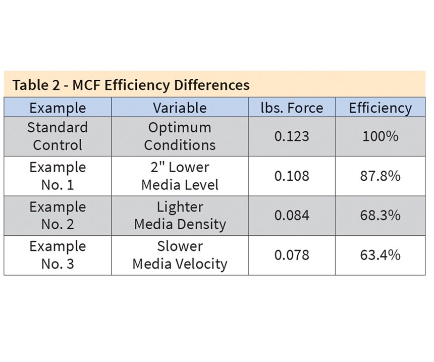
- MCF = (m/g)(v²/r) = [9.63 lbs. ÷ 32 ft./sec.²][(0.654 ft./sec.)² ÷ 1.04 ft.] = 0.123 lbs. media contact force
MCF Example 2: The Two Effects of Media Attrition
Effect 1: In this example, all variables from before are the same, except media attrition has resulted in a 2-inch loss in media height. The diameter of the vertical roll circle is now 23 inches and the circumference of roll is shorter, as follows 3.14 × 23 in. = 72.22 in. Assuming four rolls in a 60-second lap, velocity is reduced from 471 in./min. as follows:
- Radius of media mass = 23 in. ÷ 2 = 11.5 in. where 11.5 in. ÷ 12 in./ft. = 0.96 ft.
- Vertical distance = 4 × 72.22 in. = 289 in.
- Horizontal distance traveled = +157 in.
- Distance per minute = 446 in.
- V = 446 in./min. ÷ 12 in./ft .= 37.17 ft./min.
- V = 37.17 ft./min. ÷ 60 sec./min. = 0.62 ft./sec.
Effect 2: The shorter column of media decreases the lbs. of media above the part calculated as follows:
- 5.33 in.² × 23 in. = 122.59 in.³
- 122.594 in.³ ÷ l,728 in.³/ft.³ = 0.071 ft.³ media
- Wt. = 0.07l ft.³ × 125 lb./ft.³ = 8.88 lb.
Example No. 2: MCF calculation as affected by Media Attrition
MCF = (m/g)(v2/r) = [8.88 lb. ÷ 32 ft./sec.2][(0.62 ft./sec)2 ÷ 0.96 ft.] = 0.108 lb. of media contact force.
To determine optimum operations, quantify the correct roll velocity, media height and media composition density. Using the MCF and this data, calculate the applied media contact force as a control standard for the specified part.
If media attrition decreases the height of the media mass, the MCF can be used to quantify the reduction of applied media contact force versus the established control. If the velocity of the mass changes because of a heavy or light part load, the MCF can again be used to quantify the new applied media contact force versus the established control. If a media with different composition and weight density is employed, the MCF can again be used as a comparison to the established control standard value.
William Nebiolo is with REM Surface Engineering; visit remchem.com. Photos courtesy of the author. A complete version is available at short.PFonline.com/NASF17Jan1.
Originally published in the May 2017 issue.
Related Content
Having a Blast: Best Practices for Media Blasting
5 considerations for media blasting as surface preparation for coatings.
Read MoreEngineered Shaped Grain Abrasives Take Grinding Productivity to New Heights
Unique three-pointed curved grain approach offers advantages for tough grinding applications.
Read MoreAI-Powered Robotic Solutions Support High-Mix Finishing
AI startup offers automation innovations for high-mix, high-variability, manual surface finishing applications.
Read MoreHubbard-Hall Technical Team Adds Senior Chemist to Staff
David Keller is joining the Hubbard-Hall technical team as a senior chemist.
Read MoreRead Next
A ‘Clean’ Agenda Offers Unique Presentations in Chicago
The 2024 Parts Cleaning Conference, co-located with the International Manufacturing Technology Show, includes presentations by several speakers who are new to the conference and topics that have not been covered in past editions of this event.
Read MoreDelivering Increased Benefits to Greenhouse Films
Baystar's Borstar technology is helping customers deliver better, more reliable production methods to greenhouse agriculture.
Read MoreEpisode 45: An Interview with Chandler Mancuso, MacDermid Envio Solutions
Chandler Mancuso, technical director with MacDermid Envio discusses updating your wastewater treatment system and implementing materials recycling solutions to increase efficiencies, control costs and reduce environmental impact.
Read More

