Defects in Hard Chromium Deposits Part I: Causes and Cures
The causes of and remedies for defects in hard chromium deposits are explored in the first of this two-part P&SF article from 1984. Photomicrographs and SEM (scanning electron microscope) photographs will illustrate that most defects in various hard chromium deposits arise from defects in the basis metal. These defects may be in the original metal surface or may be caused by preplate finishing. Homogeneous hard chromium deposits can be produced only by eliminating these defects. Practical suggestions and procedures will be given.
by
M&T Chemicals, Inc., Research Laboratory, Rahway, New Jersey, USA
Editor’s Note: Originally published as H. Chessin, E.C. Knill & E. Seyb, Plating & Surface Finishing, 70 (2), 24-29 (1983), this is the first of a two-part paper based on a presentation given at AESF SUR/FIN 1981 in Boston, Massachusetts. This paper won a Silver Medal for Outstanding Paper published in Plating & Surface Finishing in 1983; the award was presented at SUR/FIN 1984 in New York, New York. A printable PDF version is available by clicking HERE.
ABSTRACT
The causes of and remedies for defects in hard chromium deposits are explored in the first of this two-part article. The second segment will address prevention, detection and repair.
Visible defects on the surfaces of hard chromium deposits are frequently encountered. Correct identification of the causes of these defects is a problem faced both by chromium platers and their customers. This article defines potential sources of such problems influenced by improper plating solutions, poor handling practices, and defects in the basis metal.
The plater should first recognize that the majority of pits, nodules and trees found on chromium deposits originate in the basis metal or from preplate preparation and are not caused by substandard electrolytes. Even if only one workpiece is plated satisfactorily during a period when rampant defects are observed, it is most unlikely that the plating solution is at fault. The plater, as a rule of thumb, initially should look elsewhere for the source of the problem.
Still, there are many pitfalls to which platers may fall prey as a result of electrolyte inadequacy. That's where we will begin.
Defects caused by solutions
Defects can be caused by the plating solution if the composition is incorrect or if magnetic or adhesive particles are allowed to accumulate. Solutions containing a very high ratio of chromic acid to catalyst may produce defects observed as large, approximately 3-mm-diameter (1/8-in.-diameter), light-colored pits, "clam shells" or "half-moons."1 These defects are characteristic of solutions very low in catalyst concentration.
Properly balanced solutions containing high concentrations of metallic impurities will result in deposits exhibiting rough, nodular surfaces more readily than those free of contaminants. Solutions with a total concentration of 10-15 g/L (1.5-2.0 oz/gal) of iron plus trivalent chromium have been operated successfully, but for deposits greater than about 0.13 mm (5 mil) in thickness, differences in roughness may be perceptible when the Fe + Cr+3 concentration exceeds 4 g/L (0.5 oz/gal).
Floating non-adhesive and nonmagnetic sediment in the plating bath has no effect on vertical surfaces. Except when freshly prepared, most chromium plating baths contain an appreciable quantity of insoluble lead chromate from the anodes, as well as barium sulfate from additions of barium carbonate. Very few platers have found it advantageous to filter their chromium plating solutions. Those who do must produce high-quality deposits with a thickness in excess of about 0.13 mm (5 mil).
However, contamination from several "platers' aids" can cause serious defects in hard chromium deposits. Sources in this category include platers' tape, plastic balls, plasticizer, stop-off lacquer, and wire brushes.
Adhesive particles from grease or tape tend to float on the surface of the solution and can adhere to the work as it is introduced to the bath. Such insoluble materials can cause misplating and pitting.
Floating plastic balls employed to control fumes from plating solutions have been known to pick up wax or degrade and form a sticky coating. When the workpiece enters the bath and rubs against soiled balls, it may assimilate such a film, resulting in deposit defects. Moreover, plasticizer from flexible PVC tubing may exude from the surface, forming a very adhesive film that will cause defects if the tubing contacts a clean workpiece.
Incomplete removal of stop-off lacquer or wax from the workpiece is a persistent cause of rejects. Thinners and solvents should not be used to remove lacquer or wax from work because thin films remaining after washing are extremely difficult to detect before plating. After the unwanted stop-off coating is peeled away with a knife, the workpiece should be cleaned with fine abrasive paper then scrubbed with pumice or "whiting" powder.
Magnetic (iron) particles such as fragments from rotary wire brushes, matter dissolved from work etched in the plating bath, debris from unplated internal areas, and "fines" ground away from rotating contacts and bearings will be attracted to the workpiece by the magnetic field formed by electrical current. These particulates will adhere to the plating surface to form nodules, in spite of solution agitation.
Preventive measures include the following:
- Skim the tank and keep the freeboard area clean.
- Eliminate the source of contamination.
- Keep the work surface wet as it enters the solution.
- Clean the work thoroughly to remove ail grease, dirt and polishing compound before plating.
- Do not buff or polish in the plating area.
- Keep the racking areas, benches, tote pans, cradles, etc., clean.
- Lacquer the ends or edges of adhesive stop-off tapes to avoid dissolution of the latex adhesive in solution.
- Clean and etch the work in separate tanks (not in the plating tank).
- Clean all the internal surfaces thoroughly or seal them tightly so they cannot contact the plating solution.
- Nickel or tin plate rotating steel sleeves or collector rings.
Defects caused by handling
Before plating, the workpiece must be handled with care to prevent contact with other surfaces. Failure to do so, for example, has caused rows of pits on plated hydraulic shafts that were stacked on iron-wheel dollies for in-plant transfer. The vibration generated by the wheels revolving on the rough floor of the plant caused fretting corrosion in spots along the lines of contact between workpieces. This problem was eliminated by installing rubber tires on the dolly wheels to minimize vibration and by placing paper between the rods to prevent metal contact.
Buffed or matte finishes should always be protected by wrapping the surface with clean Kraft paper immediately after finishing the basis metal. Several layers may be required on heavy work to provide adequate protection.
Contact with busbars also can lead to defective surfaces. When the workpiece touches the busbar during tank entry, the subsequent arcing that occurs can cause micropitting. The workpiece that contacts anodes also is susceptible to serious defects. Work that comes in contact with busbars or anodes always should be removed from the tank and suitably refinished and inspected before plating.
Careless handling is a pernicious source of defects. Workers should be aware of both proper handling techniques and their own physical actions.
Defects in the basis metal
When considering the basis metal as a source of defects, two aspects must be examined: (1) mechanical finishing and other modes of surface preparation, and (2) the metallurgical integrity of the metal at or near the surface.
Mechanical-finishing processes may be linked to the action of a plow through soil. Whether the furrow is created by the single point of a lathe tool or the many points on the multiple grains in a grinding wheel or honing stone, each plow point digs a groove and produces raised edges to the furrow. These raised edges usually contain splinters and microburrs of metal. The sharp edges and points of metal so produced become centers of high current density at which chromium deposition is initiated, as was demonstrated by Jones and Kenez in AES Research Project 14.2 These sites become the seeds of nodules, which in hard chromium deposits are frequently troublesome because post-plate grinding tends to tear them out, leaving pits.
Figure 1 illustrates a shaft of 4140 steel that was ground to a 16-μm (rms) finish and plated with 0.5 mm (20 mil) of chromium. The deposit was covered with nodules and gas streaks. Figure 2 shows a magnified gas streak originating at a large basis-metal defect. The chromium was anodically stripped. Microscopic examination of the surface of the basis metal (Fig. 3) revealed evidence of forced grinding. The basis metal was ground so strenuously that the surface became work hardened and the tensile stress produced cracks in the surface perpendicular to the direction of grinding.
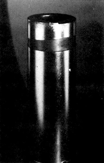
Figure 1 - Steel shaft ground to a 0.4-μm (16 μ-in., rms) finish and plated with 0.5 mm (20 mil) of chromium.
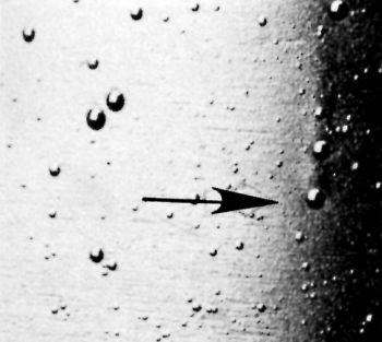
Figure 2 - Magnified gas streaks originating at nodules grown over basis-metal defects.
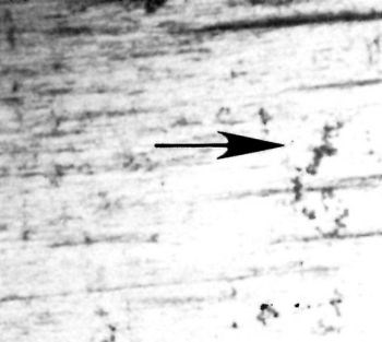
Figure 3 - Stress cracks in basis metal perpendicular to the direction of grinding. These are caused by forced grinding.
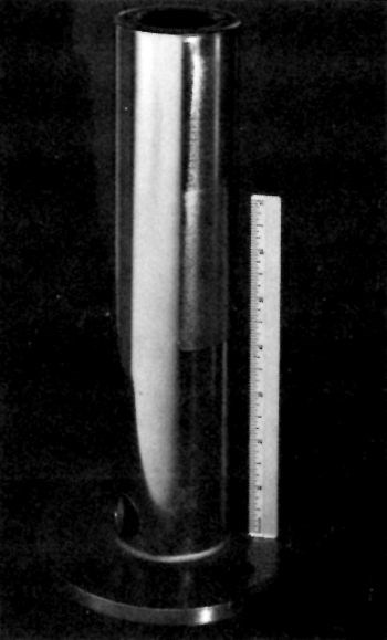
Figure 4 - Ground and chromium-plated steel shaft prefinished by buffing (L) and by paper polishing (top and bottom, right side). Center section of right side was plated directly over the ground surface.
A similar shaft (Fig. 4) was mechanically finished by different methods prior to plating. The results are illustrative of the effect of each treatment. The entire shaft was originally severely ground before receipt, at a laboratory. A central circumferential strip was untouched and circumferential strips on either side were "shoe-shined" (manually abrasive polished without backup support, e.g., as with shoe-shine polishing cloth) on the lathe with a series of increasingly fine abrasive papers: 320 emery followed by 400- then 600-grit silicon carbide. Next, longitudinal strips were further treated perpendicular to the paper-polished circumferential strips and extending approximately one quarter to one-third around the shaft. One portion was buffed on a wheel using a "steel cutting" compound. Another strip was dry-blasted with 120-grit alumina. A third strip was untouched. The surfaces so produced are shown in the photomicrographs of Figs. 5 through 10.
Figure 5 shows the ground steel surface before and after plating. The chromium deposit is extremely nodular, with nodules aligned along the grinding furrows.
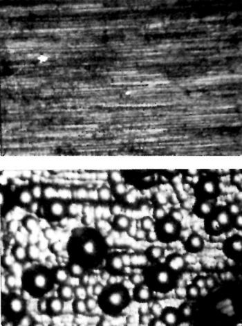
Figure 5 - Ground steel surface before (top) and after (bottom) chromium plating.
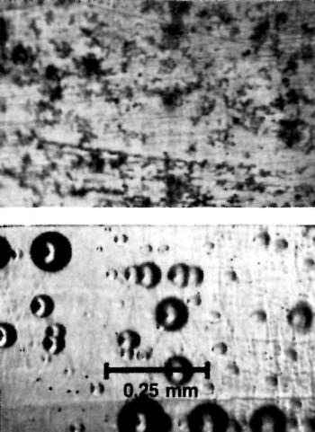
Figure 6 - Ground steel surface paper polished to a 600-grit, silicon carbide finish before (top) and after (bottom) plating.
Figure 6 shows the paper-polished surface before and after plating. Many of the grinding lines evident in Fig. 5 (top) have been removed, but there are remnant scratches and residual asperities. However, the chromium-plated surface represents a considerable improvement over that in Fig. 5 (bottom).
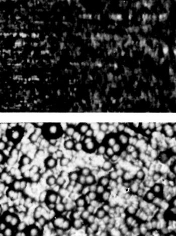
Figure 7 - Ground surface blasted with 120-grit alumina before (top) and after plating.
In Fig. 7, grinding lines are still evident in the ground surface blasted with alumina and the chromium deposit is very nodular.
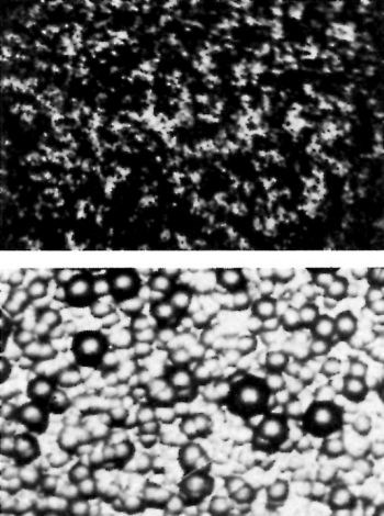
Figure 8 - Ground and paper-polished surface blasted with alumina before (top) and after (bottom) plating.
Figure 8 shows the paper-polished surface blasted with alumina. Grinding lines are no longer present but a heavily nodular surface appears on the chromium as a result of blasting.
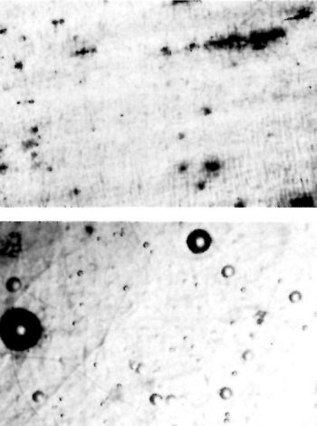
Figure 9 - Ground and lightly buffed surface before (top) and after (bottom) plating.
The ground and buffed surface is shown in Fig. 9. Buffing produced a striking improvement in the smoothness of the chromium deposit. On the ground, paper-polished and buffed surface shown in Fig. 10, aligned spots appear. These are attributed to the bleeding of a rust inhibitor and are indicative of relatively deep grinding scratches. Paper polishing improved the surface but did not go deep enough to remove all the grinding imperfections.
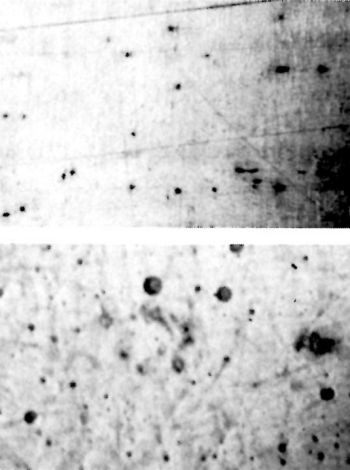
Figure 10 - Ground, paper-polished and lightly buffed surface before (top) and after (bottom) plating.
Before plating, the steel shaft was anodically etched for a few seconds to minimize changes in the steel surface. It was then plated with a 0.2-mm-thick deposit in a commercial chromium plating bath.
The example illustrates that a "perfect" surface and deposit can be obtained only by completely rectifying the damage caused by mechanical finishing. This can be achieved by taking lighter cuts with a frequently dressed, sharp grinding wheel on successive passes, thereby removing deep grooves and substituting shallower ones that can be removed subsequently by polishing and buffing or alumina blasting. It should be noted that a sharp, freshly dressed grinding wheel, when properly lubricated, may produce less surface damage than a finer-grit wheel that is glazed and dull or operated with inadequate lubrication.
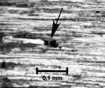
Figure 11 - Abrasive particle embedded in the basis metal surface.
rinding itself can cause pitting by embedding grit particles into the metal surface. Figure 11 illustrates a grit particle that has been broken from the wheel and remains embedded in the surface.
Burnishing a heavily ground surface with a glazed wheel does not suffice. Although the surface may be extremely smooth, the adherent but tensile-stressed chromium plate can later lift slivers and microburrs to form nodules. It is necessary to remove these slivers from the basis-metal surface before plating. After the damage in the surface has been corrected by careful grinding or honing, several methods are available to remove the last of the microburrs. These include lubricated belt polishing, vapor blasting, greaseless wheel polishing, buffing with a cutting compound, "super finishing" (or Microstoning*) and electropolishing. For further information on grinding techniques, a good source of information is the Metals Handbook on machining produced by the American Society for Metals, Metals Park, OH 44073.
Surface preparation
Roughness after chromium plating is often the result of improper basis-metal finishing. Surface improvement can be achieved by the following conventional preparatory methods.
Abrasive belt polishing
This technique is far less likely to produce surface damage than is hard wheel grinding. To improve the surface, the belt should be well lubricated and supported by a low-Durometer (60 or less) rubber wheel or even unsupported at the point of contact. The size and type of grit employed depend on the kind of basis metal and the degree or depth of damage. The technique used for the demonstration piece in Fig. 4 provides an excellent method of determining which finish and how much additional finishing will be required.
Wheel polishing
Soft wheel polishing as provided by greaseless polishing or buffing is an excellent technique for improving surfaces exhibiting only minor damage. Ground surfaces with a roughness reading below 10 μ-in. (rms) usually are readily improved by soft wheel finishing.
Buffing is usually performed with a sisal buff using a high-quality stainless-steel cutting compound. Greaseless polishing should be performed using a greaseless compound containing 120-grit (or finer) aluminum oxide abrasive on a high density-muslin, firmly packed, folded buff wheel or one made of sewed buff sections. Because of the relatively small amount of stock removed by these methods, there is little danger that dimensions will be significantly altered or distorted by these additional finishing steps.
It is good practice, whenever possible, to polish or buff across the scratches from the previous finishing operation. This reduces the likelihood that a few random scratches will remain in the final finish, and it also minimizes the amount of stock removed from the surface to achieve complete removal of ail damaged metal from the previous operation. For this reason, it also helps to minimize finishing costs.
Soft wheel finishing, especially buffing, provides an excellent method of detecting very small pits. The action of the buffing wheel is to cut more severely on the back or trailing edge of the defect, thus enlarging and scalloping it into a "fish-tail" or "comet-tail" streak. Skilled buffers frequently change the buffing direction and use firm wheels to minimize this "dragging" effect. The result is that the edges of the pit have fairly uniform radii. The net effect is that the pit is enlarged at the surface and its edges become highly reflective, greatly increasing its visibility.
Blasting
Both vapor and dry blasting with fine (120- to 320-grit) alumina are excellent methods of removing small slivers or broken crystalline debris, as illustrated in Figs. 12 and 13, without significantly disturbing the sound crystalline structure below the damage. Although all mechanical finishing procedures produce some surface disturbance, those recommended in this article are specifically designed to remove severe crystalline damage. Such damage cannot be removed readily by chemical or electrochemical treatments (except for electropolishing) without producing excessive smut on the surface or deep etching. Such etching may promote intergranular attack, thus weakening the surface crystalline structure.
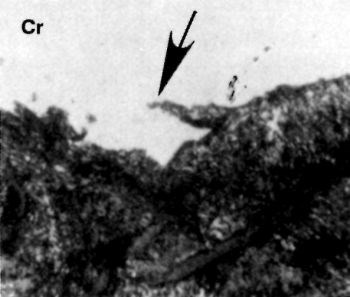
Figure 12 - Cross section showing a silver in the pearlitic cast-iron basis-metal surface.
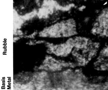
Figure 13 - Cross section showing rubble under chromium deposit. This is caused by severe honing of cast iron.
Severe crystalline damage must be prevented. The plater should strive to produce a slightly disturbed layer that can be removed with a normal etching procedure. Figure 7 shows the nodular appearance of the chromium deposit on an alumina-grit-blasted surface. Grit blasting is not harmful to the final finish, provided that the depth of attack is not so great that the pattern produced cannot be removed easily when the plated work is finished by grinding or polishing.
While the presence of many asperities on the blasted surface reduces the high current density that is attracted to a few widely scattered points on a non-blasted surface, it is sometimes desirable to reblast with a fine abrasive (e.g., 240-grit), preferably at an acute angle to the surface to reduce roughness and refine the finish. Other techniques for achieving this refinement of a blasted surface may range from slack-belt polishing to light buffing, hand polishing or wiping with a well-worn abrasive belt.
Aluminum oxide dry blasting may improve the surface condition by:
- Removing slivers.
- Replacing tensile stress, if present on the surface, with compressive stress, which resists fatigue failure.
- Reducing or eliminating the need for heavy etching or pickling, thus minimizing the risk of hydrogen embrittlement caused by prolonged pickling.
- Exposing deep cracks or pits that have been sealed and hidden by a thin layer of smeared debris from grinding, honing, burnishing or similar debris forming finishing methods. After the debris has been removed by blasting and the surface is washed with or dipped in a high-flash-point organic solvent (e.g., Stoddard's solvent), the crack will be exposed prominently because it will remain wet when the rest of the surface is dry.
Very fine cracks or pits in malleable basis metals may be cut away by the abrasive action or sealed by the compressive forces of blasting. This action not only reduces a troublesome source of surface defects, but may also temper the severity of hydrogen embrittlement if the basis metal is subject to hydrogen damage.
Mass finishing
Typical mass finishing methods, including tumbling, vibratory finishing, centrifugal barrel finishing, spindle finishing and various proprietary combinations of these, are used to progressively descale, deburr and refine the surface finish. The work is submerged in a loose abrasive media in a suitable lubricating and cutting fluid while the various motions produce both sliding and impact abrasion of the work.
Mass finishing with loose abrasive normally is suitable only for relatively small parts such as those for cameras, office equipment, and hand tools. However, equipment for processing bulk work is being manufactured in increasingly larger dimensions and may be suitable for finishing some sizable parts for functional chromium plating.
The advantages of most mass-finishing methods are similar to those of blasting. The cost is low, the finish is uniform on exterior surfaces, and the energy transferred at the work surface is of relatively low density, resulting in metallurgically clean and compressively stressed surfaces. The original tumbling processes were slow, but, today, vibratory, centrifugal, and spindle-type mass-finishing processes can provide superior finishes at relatively rapid rates. If time is not a critical requirement, a simple tumbling barrel may be adequate at a modest capital cost. Increasing the speed of rotation accelerates the rate of cutting and the depth of compressive stress created in the surface, but the finishes attainable are not as fine as those achieved at low speed.
Vibratory finishing has the advantages vs. tumbling of processing larger parts, producing greater motion in recesses, and reducing cycle time. In addition, parts may be inspected without interrupting the process. Vibratory finishing also can be fully automated where desirable.
Centrifugal barrel finishing is faster than vibratory finishing but its most important characteristic is the capability to produce high compressive stress in the work surface, reducing the risk of fatigue failure. Centrifugal disc machines offer similar advantages but without quite the speed or precision of the centrifugal barrel machines. The principal advantages of the centrifugal disc units vs. the barrel types are (1) an open bowl that permits faster loading and unloading of the work, and (2) the capability to inspect work in progress.
The most rapid mass finishing usually can be achieved with spindle-type machines, in which the work is fixtured in a rotating tub of abrasive media. While speeds of less than 1 min sometimes can be attained, the work must be fixtured by hand labor and the flow of media is more prone to be directional by comparison with the mass-finishing processes previously mentioned.
Peening
Like grit blasting and mass finishing, peening provides a means of producing compressive stress in the surface and sealing minor surface pits and cracks in malleable basis metals. Unlike the aforementioned finishing methods, peening is not well suited for improving or refining the surface finish. Indeed, the use of shot or hammer peening usually degrades the finish by producing pock marks that must be removed by subsequent finishing methods.
Shot blasting is performed with spherical steel pellets impelled to the surface by an air blast or by centrifugal force from a high-speed rotor. Unfortunately, most shot commercially employed features a flash that results in numerous tiny cuts, along with the pockmarks, on the final finish.
Hammer peening normally refers to the production of a peened surface using a pneumatic hammer. The hammer may be set up on a lathe or other machine tool capable of traversing the work past the rapidly reciprocating hammer. The hammer is usually mounted on a carriage so that it can be traversed in the same manner as a cutting tool.
Burnishing
Like hammer peening, burnishing is performed by machine. The burnishing tool is extremely hard, frequently chromium plated, highly finished, and smoothly curved. As it is traversed across the work surface, exerting extremely high unit pressures, it is lubricated to prevent scoring or displacement of particles from the surface. On cylindrical parts, the tool normally produces a shallow helical groove in the work surface.
Burnishing produces compressive stress, as in peening operations, but the crystalline structure is deformed unidirectionally. When skillfully performed, it is possible to seal very fine pits and cracks in malleable metals. Surfaces may require a final finishing operation before plating to reduce the depth of the helical track produced by the burnishing operation on rotating cylindrical work.
Roller burnishing is used primarily to size internal diameters and to produce work-hardened components with smooth surfaces. It is an effective finishing method for malleable ferrous and nonferrous metals and alloys. A similar sizing and finishing operation is often associated with broaching. Burnishing may be the function of the last two or three steps on the broach or it may require a separate tool in the same form as the broach.
Ball burnishing is performed on small parts in tumbling barrels and similar mass-finishing equipment. It may be combined with a lubricating slurry containing a suitable fine abrasive that produces a highly polished, completely debarred product with all corners and sharp edges smoothed to uniform radii.
Ball burnishing is widely used on malleable basis metals and also on hardened steel parts such as bearing balls. The result frequently is a highly polished, compressively stressed final finish. Work finished by ball burnishing normally is ready for plating and requires no additional finishing.
Metal integrity
Proper mechanical preparation minimizes the formation of surface defects. However, there is still another common source of defects: heterogeneities in the metal itself. These basis-metal defects are often characteristic of the type of metal to be plated, the metallurgical treatment of the metal, the metalworking process used to prepare the work for plating, or improper storage and handling. The knowledgeable plater is in a good position to inspect the work for defects. For example, cast and chilled iron frequently have pits or gas pockets that can be seen with the naked eye or with low-powered magnification. Cold-rolled steel may have seams, slivers, blisters, or pipe lines that run in the direction of rolling or drawing. Hardened steel may have thermally induced stress cracks difficult to detect without etching the steel to expose them. The same forming processes may produce similar defects in non-ferrous metals and alloys.
Oxides or scavenger reaction products on the substrate may create problems if they are not finely dispersed in a homogeneous distribution and if present as gross heterogeneous accumulations. The electrochemical nature of these inclusions is especially critical in determining whether they are harmful or not. If the hydrogen overvoltage of the inclusion is lower than the deposition potential of the metal to be plated, hydrogen will be evolved preferentially from this point on the surface of the cathode, resulting in the formation of a typical conical gas pit. If the inclusion is electrochemically inert (e.g., slag or glass in wrought iron) it will be bridged quickly by the deposit. Inclusions of unalloyed metals such as lead in some free machining steels are normally harmless. Free graphite in cast iron and some high-carbon steels does not create a problem for the plater unless the metal is subjected to excessive etching procedures that cause the graphite to accumulate on the surface of the work, making it very difficult to cover with a chromium deposit. Poor adhesion or roughness will result if chromium is deposited over the exposed carbon layer.
Welds are a frequent source of defects, ranging from gas pits and foreign inclusions to oxidation and thermally induced metallurgical damage to adjacent surfaces. Special attention must be given to welded components if the welded areas are to be plated with chromium and must be free of defects.
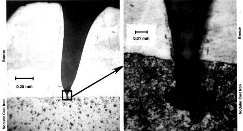
Figure 14 - (A) Bronze deposit over nodular cast iron containing a basis-metal pit; (B) enlargement shows contour of substrate defect.
igure 14 includes two photomicrographs of bronze electrodeposited on ductile cast iron. These images are included because the metallographer was able to bisect the fault in the basis metal, a very difficult task. The higher magnification (Fig. 14, right) shows that a very small pore in the basis metal resulted in a very large pit in the electrodeposit (Fig. 14, left).
The surface of the chromium deposited in the base of a housing for a rotary engine showed cracks atypical of the usual chromium cracking (Fig. 15). A cross section (Fig. 16) shows that these defects started at the basis metal as surface stress cracks caused by cold-working or heavy grinding. The interceptions may have been related to the graphite flakes of the cast iron.
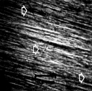
Figure 15 - Chromium-plated surface of housing for a rotary engine showing atypical cracking.
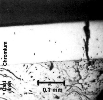
Figure 16 - Cross section of surface shown in Fig. 15.
Summary
Experience, confirmed by experiment, shows that many of the common defects in hard chromium deposits arise from improperly prepared basis metals. For example, slivers and burrs are commonly burnished into the surface, only to rise later under the tensile stress of the chromium and cause problems. Proper finishing methods to remove these silvers and burrs are necessary. In addition, the importance of metallurgical homogeneity for flaw-free chromium plating should not be understated.
This survey of problems frequently encountered in hard chromium plating should provide the metal finisher with insight about how they originate. It is clear that the task of producing sound hard chromium deposits depends not only on the role of the finisher, but on that of the manufacturer and fabricator as well.
References
1. D.R. Millage and W.E. Hague, Proc. AES 45th Ann. Tech. Conf., 38, 118 (1958).
2. M.H. Jones and M.G. Kenez, Proc. AES 51st Ann. Tech. Conf., 44, 23 (1964).
Footnote:
*Tradename of Taft Pierce, Providence, RI.
About the Authors
Dr. H. Chessin is a senior research associate at the Research Laboratory of M&T Chemicals Inc., P.O. Box 1104, Rahway, NJ 07065. He joined M&T in 1962 and has headed the company's chromium research group for decorative and functional plating. He has more than 30 years of experience in the metal finishing industry. Dr. Chessin received his Ph.D. degree from Western Reserve University, Cleveland. He is a member of the AES, the Electrochemical Society and the National Association of Corrosion Engineers and the author of several patents and publications.
E.C. Knill is a research associate for M&T Chemicals. He joined the company in 1970 after serving in various capacities, including technical director, for the Chromium Corp. of America over a span of 30 years. Mr. Knill holds a B.Ch.E. degree from Clarkson College of Technology and is an AES member.
Dr. Edgar Seyb is the research and development manager of M&Ts Plating Division. He has been associated with the development of electroplating processes and corrosion testing for more than 30 years, holds more than 25 U.S. patents, and has written numerous technical articles. Dr. Seyb received his Ph.D. degree from the University of Kansas. He is a member of the AES, the ASTM (serving as chairman of Subcommittee B0808 on Engineering Coatings), the Electrochemical Society, and the American Chemical Society, and is a Fellow of the Institute of Metal Finishing.
Related Content
Development of a Novel Hexavalent-Chromium-Free Aluminum Sacrificial Paint
Hexavalent chromium is a known carcinogen, repro-toxin, and mutagen. Its elimination is of high importance to the aerospace industry, which has struggled to find high performing alternatives. Legacy aluminum sacrificial paints have traditionally utilized hexavalent chromium to prevent corrosion and coatings which are equal to or better than have been difficult. This first paper discusses the novel process from the supplier point-of-view.
Read MoreSUR/FIN 2023: Capsules from the Technical Sessions I: Emerging Technologies
SUR/FIN 2023 in Cleveland this past June was a resounding success. Due to the efforts of the Technical Activities Committee, ably led by Bill Nebiolo this year, an outstanding program of technical presentations was offered. What follows are summaries of selected presentations from the Emerging Technologies sessions. Additional coverage will be provided in this space in the coming months. The full report can be accessed and printed at short.pfonline.com/NASF23Aug1.
Read MoreTin-Zinc Alloy Electroplating and Its Corrosion Behavior
An NASF/AESF Foundation Research Program Retrospective
Read MoreHighlights from SUR/FIN 2023
Products Finishing offers a recap of some of the topics that were top of mind at the SUR/FIN 2023 finishing industry trade show.
Read MoreRead Next
A ‘Clean’ Agenda Offers Unique Presentations in Chicago
The 2024 Parts Cleaning Conference, co-located with the International Manufacturing Technology Show, includes presentations by several speakers who are new to the conference and topics that have not been covered in past editions of this event.
Read MoreDelivering Increased Benefits to Greenhouse Films
Baystar's Borstar technology is helping customers deliver better, more reliable production methods to greenhouse agriculture.
Read MoreEpisode 45: An Interview with Chandler Mancuso, MacDermid Envio Solutions
Chandler Mancuso, technical director with MacDermid Envio discusses updating your wastewater treatment system and implementing materials recycling solutions to increase efficiencies, control costs and reduce environmental impact.
Read More


