Hex Chromium-Free Sealants for Defense and Aerospace
Results of second phase of research conducted by top defense contractors.
Abstract
Polysulfide sealants containing soluble hexavalent chromium compounds are used in aerospace/defense manufacturing primarily for the filling of gaps and recesses to prevent water intrusion in an attempt to prevent corrosion of the base metal. Regulatory mandates have accelerated a global effort industry wide to replace hexavalent chromium containing materials because they are carcinogens, mutagens, developmental toxicants, and have high acute toxicity. The principal technical performance challenge for transitioning to hexavalent chromium free polysulfide sealants is twofold; the corrosion inhibiting properties of the hexavalent chromium free alternatives are not well understood, and the industry and military standards’ qualification tests do not adequately differentiate between hexavalent chromium containing and hexavalent chromium free formulations.
Introduction
Regulatory mandates have accelerated a global effort in the aerospace and defense industries to replace hexavalent chromium containing materials with hexavalent chromium-free alternatives for various applications. Workplace exposure to hexavalent chromium can cause health impacts such as lung cancer and respiratory tract damage in workers who breathe airborne hexavalent chromium, and skin damage from dermal exposure1 (OSHA, 2009).
In 2006, the U. S. Government’s Occupational Safety and Health Administration (OSHA) implemented new Hexavalent Chromium Standards for general industry where the average worker exposure to hexavalent chromium over the course of an eight hour work shift was reduced from 52 ug/m3 to 5 ug/m3 2(29 CFR 1910.1026). In 2011, the following Defense Federal Acquisition Regulation Supplement (DFARS) was issued, (Subpart 223.73), “Minimizing the Use of Materials Containing Hexavalent Chromium”.3 (DFARS 2011) The supplement mandates that no Department of Defense contract (for programs prior to Milestone A 4 (as defined in Interim DoDI 5000.02, November 25, 2013) may include a specification or standard that results in a deliverable containing more than 0.1% hexavalent chromium in any homogeneous material where acceptable substitutes are available. It also prohibits the use or removal of hexavalent chromium containing materials during subsequent phases of the deliverable, unless an exception or approval applies. Sealant applications that contain hexavalent chromium are not an exception. 3 (DFARS 2011)
In today’s era of government cuts and budget constraints, funding innovative environmental solutions can be challenging. The resources required for investigating and evaluating the various hexavalent chromium free materials may be prohibitive for an individual company to undertake alone. Therefore, the Toxics Use Reduction Institute (TURI) at the University of Massachusetts Lowell reached out to companies in the aerospace/defense industry that were interested in participating in a collaborative project to address the challenges of adopting hexavalent chromium free alternatives. In 2012, a Hexavalent Chromium Free Sealant Evaluation Team was established with representatives from TURI, Lockheed Martin, Raytheon, Northrop Grumman, Bombardier, National Aeronautics and Space Administration (NASA), Naval Air Systems Command (NAVAIR), Air Force Research Laboratory (AFRL), and Army Aviation and Missile Command (AMCOM). By working together the team was able to avoid duplicated efforts and share the cost burden between the Original Equipment Manufacturers (OEMs) and the government customers looking for a shared solution. The first phase of testing used a similar test vehicle design. The key findings of the Phase 1 tests are as follows:
- 7075 alloy had higher corrosion than 6061 alloy for all sealant applications.
- Iridite had lower corrosion than hex chrome free conversion coating for most sealant applications.
- Countersunk fasteners had less corrosion resistance compared to fasteners with protruding fastener heads.
- No statistically significant difference in corrosion resistance between hex chrome containing and hex chrome free primers.
- Improved corrosion resistance when a topcoat is present.
- No statistically significant difference between the corrosion resistance performance of the hex chrome containing and hex chrome free sealants 5(MPLR 2013), 6(Metal Finishing 2013).
This article will present the results of the second phase of research conducted during 2013 by the Evaluation Team to evaluate sealants with hexavalent chromium free corrosion inhibitors.
Evaluation Process
Industry specification test procedures for sealants currently do not provide sufficient and differentiable criteria for evaluating chromate and non-chromated materials in field applications where corrosion is expected to occur as a result of the environment. Therefore, for Phase II the Evaluation Team developed a single test vehicle configuration to evaluate the following sealant applications: wet installation of fasteners, sealing over the head of a fastener, sealing of faying surfaces and butt joint sealing. The sealant applications chosen are a few of the most common uses of sealant on aircrafts, and would therefore be a good indicator of sealant performance. The testing was modeled after MIL-PRF-81733, but was modified to better distinguish between sealants given the limited timeframe available to conduct the test by inducing failures (through preconditioning and scribing). Industry certified sealants were selected for Phase 2, and only the corrosion inhibiting capability of the sealants was evaluated.
A total of thirty test vehicles were assembled to provide a design of experiment that included five replicates for each of the six types of sealants included in the evaluation. Each test vehicle had only one type of sealant applied. The six types of sealants selected for this evaluation are shown in Table 1. The PS-870 sealant contains a hexavalent chromium corrosion inhibitor and serves as the baseline control sealant for the evaluation. Four sealants with non-hex chrome corrosion inhibitors were chosen for the evaluation: AC-735, PR-1775, PR-2870, and CS 5500N CI. The PR-1440 sealant does not contain any corrosion inhibitor and serves as the negative control for the evaluation.
Table 1: Six Sealants Included in the Evaluation
|
Vendor |
Vendor PN |
Specification |
Purpose |
Chemical Class |
Corrosion Inhibitor |
|---|---|---|---|---|---|
|
PPG Aerospace |
PS-870 |
MIL-PRF-81733 Type II Class 1 Grade A |
Baseline/ Control |
Polysulfide |
Hexavalent chromium |
|
3M |
AC-735 |
MIL-PRF-81733 Type II Class 1 Grade B and AMS 3265 Class B |
Alternative Sealant |
Polysulfide |
Zinc phosphate |
|
PPG Aerospace |
PR-1775 |
AMS 3265 Class B |
Alternative Sealant |
Polysulfide |
Multiple Materials |
|
PPG Aerospace |
PR-2870 (RW-6040-71 ) |
MIL-PRF-81733 Type II Class 2 Grade B |
Alternative Sealant |
Polythioether |
Proprietary |
|
Flame Master |
CS 5500N CI |
Not yet qualified |
Alternative Sealant |
Polysulfide |
Molybdates |
|
PPG Aerospace |
PR-1440 |
AMS-S-8802 Type 2 Class B |
Negative Control |
Polysulfide |
None |
The test vehicle used for this analysis consisted of three aluminum plates with a series of eight matching holes through which eight threaded fasteners were inserted and then held in place by eight nuts. The ¼” fasteners used had flat, countersunk heads and were made of stainless steel alloy UNS S66286 (A286). This alloy was selected because it is commonly used in industry and created a galvanic mismatch with the aluminum plates. The aluminum plates used were made of UNS A97075 (7075) alloy, with dimensions of 0.25” thick, 2.0” wide, and 4.5” long.
This Phase II testing began in July 2013. The aluminum plates were procured by TURI and sent to NASA for machining the holes. The plates were then delivered to the Northrop Grumman facility in Linthicum, Maryland where Iridite 14-2 conversion coating was applied to thirty test vehicles in accordance with their standard operating procedures in compliance with MIL-DTL-5541. During August 2013, the test vehicles were sent to Raytheon Missile Systems in Tucson, Arizona and were assembled over a three week period using the following method.
- Cleaning: All plates were solvent wiped with Acetone (Figure 2).
Figure 2: Test plates were cleaned by solvent wiping with acetone.
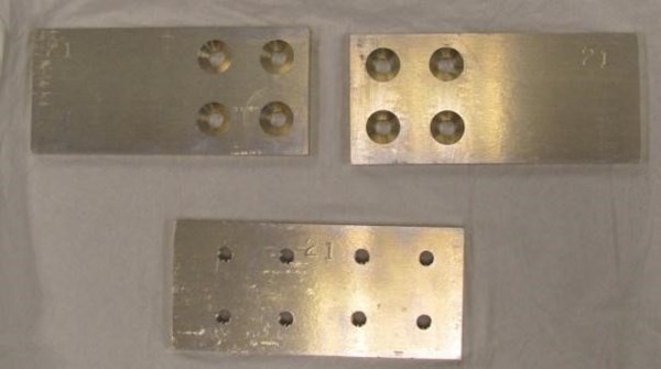
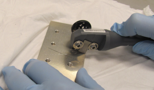
- Butt Joint Scribe: Scribes were generated by an “Erichsen Scratch Stylus Acc to Sikkens Model 463” with a 1 mm wide carbon tip. Scribed an “X” on the top side of the bottom plate (Figure 3).
Figure 3: Cleaned test plates were scribed with an "X".
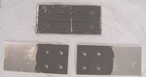
- Faying Surface: All sealants were mixed in accordance with manufacturer’s instructions and a smooth even coat of sealant (thickness of 0.005 inch) was applied to both sides of the mating panels using an orange stick or glass rod (Figure 4). Five mil bond wires were used to control the thickness and the panels were placed together so the holes aligned.
Figure 4: Sealants were applied to faying surfaces of the test plates.
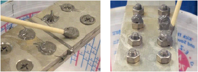
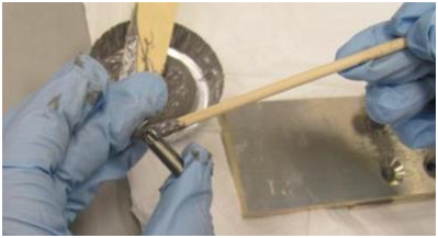
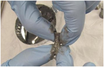
- Application of Sealant to Fasteners: Fasteners were cleaned with acetone prior to installation. All 8 fasteners were evenly coated with sealant using an orange stick or gloved finger (Figure 5).
Figure 5: Fasteners were coated with sealant, using an orange stick (left) or gloved fingers (right)
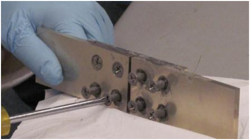
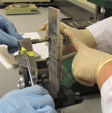
- Installation of Fasteners. Fasteners were inserted into the holes of the freshly mated panels and nuts were installed on the opposite side of the plate (Figure 6). All fasteners were hand tightened with a screwdriver. Then the plate was held in a vice and all eight fasteners were torqued to 40 in-lbs (Figure 7).
Figure 6: Fasteners were inserted and nuts installed, then hand-tightened.

|
Figure 7: A screwdriver was used to tighten the installed fasteners (left) and then the fasteners were torqued to 40 in-lbs (right). |
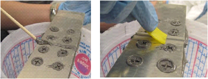
- Butt Joint: Sealing compound was applied to the butt joint to completely fill the gap using an orange stick or glass rod (Figure 8).
|
Figure 8: Sealing the butt joint |
-
Clean: Excess sealant was wiped from the entire test vehicle with cotton swab and acetone to remove the majority of the sealant from the exterior prior to proceeding (Figure 9).
|
Figure 9: Excess sealant was wiped away using cotton swabs and acetone.
|
- Fastener Heads: An orange stick or glass rod was used to apply sealant to completely cover over and around six fastener heads, as well as the corresponding six nuts on each test vehicle (Figure 10).
|
Figure 10: Heads of the fasteners (left) and nuts (right) were completely covered with more sealant.
|
- Excess Sealant Removal: All the residual sealant from the processing of the test vehicle was removed.
- Curing: The assembly cured for 48 hours at ambient laboratory temperature with the relative humidity between 35 and 48%.
- Prime and Paint: Following a surface wipe with acetone, primer (PPG Aerospace 44GN098) and topcoat (PPG Aerospace CA 8211/F37886) were applied to the test vehicles according to manufacturer instructions. Test vehicles were allowed to cure for a minimum of 48 hours prior to scribing.
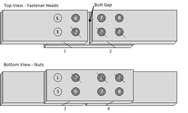
- Additional Scribes: Additional scribing was done through the primer/topcoat across the edges of the test vehicle in four locations and on fastener heads and nuts as follows:
Fasteners 1, 5: No sealant, no scribes
Fasteners 2, 3, 4: Sealant protection, with scribes
Fasteners 6, 7, 8: Sealant protection, no scribes (Figure 11).
Figure 11: Placement of Additional Scribes.
- Final Packaging and Shipment: Test vehicles were wrapped individually wrapped in K-Drys and sent to NAVAIR for preconditioning.
The completely assembled, painted, and scribed test vehicle is shown in Figure 12.
Figure 12: Assembled Test Vehicle, Top, Bottom, and Side Views


To stress the sealant joints, the test vehicles were mechanically and thermally preconditioned at the NAVAIR facility in Patuxent River, Maryland during September 2013. The preconditioning was conducted according to MIL-PRF-81733D Section 4.8.9.3.1 Cyclic Loading for Class 1 materials. The assemblies were installed vertically in the jaws of a machine and loaded between 0 and 5,000 lb for 250 cycles with a loading rate of 10 inches (254 mm) per minute. The assembly was subjected to 250 cycles at a temperature of -65 °F (-54 °C) following a 30 minute soak time at -65 °F (-54 °C) under no load.
After completion of preconditioning, twenty-four test vehicles (four test vehicles for each of the six sealant types) were sent to Lockheed Martin Aeronautics at their Fort Worth, Texas facility for accelerated corrosion testing. The test vehicles were exposed to sulfur dioxide (SO2 ) salt fog for 1,000 hours per ASTM G85 Annex 4. This test consisted of spraying neutral pH salt fog with the introduction of SO2 gas directly into the chamber for one hour of a six hour cycle. The pH of the salt fog was kept in the range of 2.5 – 3.2. 5 (Lockheed Martin, 2013)
The remaining six test vehicles (one test vehicle for each of the six sealant types) were sent to the NASA Beachside Atmospheric Test Facility located at Kennedy Space Center, Florida. The beachfront testing is occurring over a twelve month duration between November 2013 and November 2014. The results of this long term corrosion testing can be obtained from the authors by request.
Results and Conclusions
It is important to note that each of the sealant products in this study have been individually qualified to their respective specifications. The test results and conclusions of this study are based solely on the specific, yet limited testing effort of corrosion resistance to environmental conditions in simulated field applications where damage is expected. The results are not intended to be an endorsement or disapproval of the various sealant products included in the test. For the purposes of this research, we considered the results to be statistically significant if the Confidence Level was at least 90%, with a corresponding alpha risk of 10%. If the results for any area of inspection did not meet this requirement, then they were not included in this article.
After the accelerated salt fog test was completed, the twenty-four test vehicles were disassembled so that the coating, sealant and corrosion by-products could be removed to reveal the inner surfaces that were protected by sealant and assess the resulting corrosion to the base metal. The test vehicles were then inspected for the presence of corrosion in the three major areas that were protected by sealant:
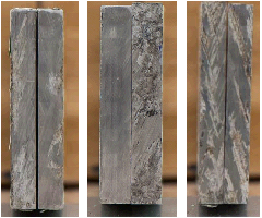
- Faying Surface (See Figure 13) and Butt Joint Areas (See Figure 14)
- Fastener Hole Area: including both the countersink and hole barrel areas (See Figure 15)
- Exterior Surface: ring areas around the fastener holes that were covered with sealant. For the top plate this ring area was approximately 0.1 inches wide, and for the bottom plate this was approximately 0.25 inches wide.
|
Figure 13: Examples of Corrosion in Faying Surfaces of Baseline, Hex Chrome Free Sealant and Negative Control after Sealant Removal.
|
|
Figure 14:Examples of Corrosion in Butt Joint of Baseline, Hex Chrome Free Sealant and Negative Control after Sealant Removal.
|
|
Figure 15: Examples of Corrosion in Countersunk Hole for Baseline, Hex Chrome Free Sealant and Negative Control after Sealant Removal.
|
Because of the large amount of surface area that each sealant had to protect, the butt joint and faying surface category was regarded as the primary performance indicator of the overall sealant corrosion inhibition.
Ratings for the amount of corrosion in each area of interest were recorded as a percentage of corrosion observed for each area examined. Corrosion was only recorded if there was deterioration of the metal (pitting). A rating of 0% would reflect that no corrosion was present and a rating of 100 % would indicate complete corrosion of that area of interest. For each type of sealant, there were four test vehicles that were averaged together to provide a single corrosion rating. Table 2 presents the inspection results for the twenty-four test vehicles that completed 1,000 hours of SO2 salt fog exposure.
Table 2: Corrosion Inspection Results by Sealant Product for Faying Surface and Butt Joint
|
Surface Area |
PS- 870 |
AC-735 |
PR-1775 |
PR-2870 |
CS 5500N CI |
PR-1440 |
All Six Sealants |
Four Cr-Free Sealants with CI |
|---|---|---|---|---|---|---|---|---|
|
Faying Surface Area |
2.7% |
1.1% |
2.6% |
3.0% |
3.1% |
5.2% |
2.9% |
2.4% |
|
Butt Joint Area |
6.2% |
7.9% |
2.8% |
5.5% |
6.3% |
10.8% |
6.6% |
5.6% |
|
Combined Faying Surface & Butt Joint Areas |
3.0% |
1.6% |
2.7% |
3.1% |
3.3% |
5.7% |
3.2% |
2.7% |
According to Table 2 information, for the combined faying surface and butt joint areas, the percent corrosion values per sealant type varied from 1.6% to 5.7%. The percent corrosion for PR-1440 (5.7%), the negative control, was higher than AC-735 (1.6%), and was found to be statistically significant. Even though PR-1440 had a higher percentage of corrosion as compared to the other sealants, there was no statistical difference found for the percent corrosion levels between it and the CS 5500N CI, PR-1775, PS- 870, and PR-2870 sealants. Also, despite AC-735 having a lower percentage of corrosion compared to the other sealants, there was no statistical difference found for the percent corrosion levels between it and the CS 5500N CI, PR-1775, PS- 870, and PR-2870 sealants.
Table 3: Butt Joint Crack and Corrosion Location Comparison
|
Sealant |
PPG PS-870 |
3M AC-735 |
PPG PR-1775 |
||||||||||
|
Test Vehicle |
1 |
2 |
3 |
4 |
6 |
7 |
9 |
10 |
11 |
12 |
13 |
14 |
|
|
Crack Location |
None |
M |
R |
None |
R |
L |
RM |
L |
LMR |
LMR |
M |
LMR |
|
|
Butt Joint Side 1 L |
12 |
10 |
5 |
2 |
1 |
8 |
15 |
25 |
2 |
0 |
0 |
7 |
|
|
Butt Joint Side 2 R |
5 |
17 |
9 |
9 |
3 |
1 |
35 |
7 |
3 |
2 |
3 |
9 |
|
|
Butt Joint Total |
17 |
27 |
14 |
11 |
4 |
9 |
50 |
32 |
5 |
2 |
3 |
16 |
|
|
|
|
|
|
|
|
|
|
|
|
|
|
|
|
|
Sealant |
PPG PR-2870 |
FM CS 5500 CI |
PPG PR-1440 |
||||||||||
|
Test Vehicle |
17 |
19 |
20 |
21 |
23 |
24 |
25 |
26 |
28 |
29 |
30 |
31 |
|
|
Crack Location |
None |
R |
None |
MR |
LMR |
M |
MR |
M |
LMR |
LM |
LM |
LM |
|
|
Butt Joint Side 1 L |
2 |
0 |
0 |
0 |
8 |
20 |
8 |
2 |
14 |
12 |
21 |
16 |
|
|
Butt Joint Side 2 R |
7 |
55 |
0 |
0 |
8 |
23 |
1 |
3 |
9 |
15 |
11 |
21 |
|
|
Butt Joint Total |
9 |
55 |
0 |
0 |
16 |
43 |
9 |
5 |
23 |
27 |
32 |
37 |
|
It should be noted that during the mechanical and thermal preconditioning and the 1,008 hours of SO2 salt fog exposure, cracks in the topcoat appeared in the sealant filled area of the butt joint. The locations of the cracks were recorded prior to disassembly and compared to the percent corrosion observed after the coupons were disassembled. The crack location marks L, M, and R, as seen in Table 3, refer to the left side, middle, right side, or any combination if there were multiple cracks in the butt joint, as shown in Top View of Figure 11. There is some correlation between the percent corrosion observed on the butt joint side and the corresponding crack location of the test vehicles. However, observing a crack in the topcoat at a particular location does not always result in observing a significant amount of corrosion on the corresponding butt joint side because there is no way to determine where the crack propagates through the sealant of the butt joint area.
Table 4: Corrosion Inspection Results by Sealant Product for Fastener Hole Area
|
Surface Area |
PS- 870 |
AC-735 |
PR-1775 |
PR-2870 |
CS 5500N CI |
PR-1440 |
All Six Sealants |
Four Cr-Free Sealants with CI |
|---|---|---|---|---|---|---|---|---|
|
Fastener hole area (Holes with Sealant Overcoat and No Scribes) |
0.2% |
0.1% |
0.1% |
0.1% |
4.3% |
1.1% |
1.0% |
1.2% |
|
Fastener hole area (Holes with Sealant Overcoat and Scribes) |
10.2% |
12.8% |
9.8% |
15.9% |
8.5% |
7.8% |
10.8% |
11.8% |
|
Fastener hole area (Holes with No Sealant Overcoat and No Scribes) |
2.3% |
8.9% |
3.5% |
8.5% |
7.7% |
15.1% |
7.7% |
7.2% |
For the fastener holes with sealant overcoat and no scribes, the percent corrosion values per sealant type varied from 0.1% to 4.3% as shown in Table 4. The percent corrosion for CS 5500N CI was higher than the corrosion levels for the PS-870, AC-735, PR-1775, PR-1440, and PR-2870 sealants, and was found to be statistically significant. There was no statistical difference found for the percent corrosion values between the AC-735, PR-1440, PR-1775, PS-870, and PR-2870 sealants. For the fastener areas with 1) sealant overcoat and scribes and 2) no sealant overcoat and no scribe, there was no statistical significance found between sealant performance.
The fastener hole areas for all twenty four test vehicles with sealant overcoat and no scribes (1.0%) had lower corrosion levels than fastener holes with either: 1) sealant overcoat and scribes (10.8%) or 2) no sealant overcoat (7.7%). This difference was found to be statistically significant.
Table 5: Corrosion Inspection Results by Sealant Product for Ring Around Fastener Area
|
Surface Area |
PS- 870 |
AC-735 |
PR-1775 |
PR-2870 |
CS 5500N CI |
PR-1440 |
All Six Sealants |
Four Cr-Free Sealants with CI |
|---|---|---|---|---|---|---|---|---|
|
Ring around fastener hole areas with Sealant Overcoat and No Scribes |
0.1% |
0% |
0% |
0.3% |
2.6% |
3.4% |
1.1% |
0.7% |
|
Ring around fastener hole areas with Sealant Overcoat and Scribes |
2.4% |
3.5% |
5.4% |
5.6% |
5.4% |
14% |
6.0% |
5.0% |
|
Ring around fastener hole areas with No Sealant Overcoat and No Scribes |
9.6% |
2.5% |
5.4% |
9.2% |
39% |
33% |
16.3% |
14.1% |
|
Ring Areas Around All Fastener Holes |
3.3% |
1.9% |
3.4% |
4.5% |
12.8% |
14.4% |
6.7% |
5.7% |
For the ring around all fastener hole areas, the percent corrosion values per sealant type varied from 1.9% to 14.4% as shown in Table 5. The percent corrosion for PR-1440 and CS 5500N CI was higher than the PS-870, AC-735, PR-1775, and PR-2870 sealants, and was found to be statistically significant. There was no statistical difference found for the percent corrosion between the AC-735, PR-1775, PS-870, and PR-2870 sealants. Similar results were obtained when examining just the ring around fastener hole areas with no sealant overcoat and no scribes.
There was no statistical significance found for the ring area around fastener holes with sealant and no scribes. For ring areas around fastener holes with sealant and scribes, the PS-870 had less corrosion than the PR-1440, otherwise there was no statistical significance found.
The primer and topcoat on the surface of the test vehicles assembled with CS 5500N CI and PR-1440 sealant blistered badly during the salt fog exposure for unknown reasons, affecting these results. Future testing is being designed to further examine this phenomenon.
For the ring around fastener hole area of all twenty-four test vehicles, the fastener holes with a sealant overcoat with scribes (6%) and without scribes (1.1%) provided better corrosion protection than fastener holes with no sealant overcoat (16.3%). This difference was found to be statistically significant.
In conclusion, for all areas of interest, several alternative sealants containing non-hex chrome corrosion inhibitors (AC-735, PR-1775, and PR-2870) generally provided comparable corrosion prevention performance with the hexavalent chromium control sealant, PS-870. The CS5500N CI non-hex chrome corrosion inhibiting sealant performed well in most of the areas of interest, and may have performed comparable with the other corrosion inhibiting chrome free sealants, if not for the blistering on the surface areas of the test vehicles which could have caused a higher percentage of corrosion in those areas. The PR-1440 sealant with no corrosion inhibitor had a generally higher percentage of corrosion across all areas of interest and also blistered on the surface areas.
Next Steps
The Evaluation Team will complete the long term beachside atmospheric corrosion testing and document the results.
Acknowledgements
Tony Phillips, Kent DeFranco, Curtis Lemieux, Zachary Powell, Natalie Cowart, Susan Lewis, and Scott Jones from Lockheed Martin for technical input, accelerated corrosion testing, and corrosion analysis. Dave Pinsky, Amanda Gravanda, Dave Betzhold, and Dayna Lamb from Raytheon for technical input, test vehicle mechanical drawings, and test vehicle assembly operations. Greg Morose from the Toxics Use Reduction Institute at the University of Massachusetts Lowell for project management and statistical analysis of testing results. Steve Davidson, Eric Schoch, Hal Ozpaker, and Paul Cohen from Northrop Grumman Corp. for application of the trivalent conversion coating to the test vehicles and for technical input. Casey Yeary, Paul Robinson, and Mark Feathers from the U.S. Army for technical input. Alan Fletcher and Michelle Barga from the U.S. Air Force for technical input. Diane Kleinschmidt from the U.S. Navy for test vehicle preconditioning and for technical input. Kurt Kessel from NASA for machining the test vehicles, beachfront testing of the test vehicles, and for technical input. Mario Simard and Louis Laberge Lebel from Bombardier for technical input and providing the fasteners for the test vehicles.
References
1. OSHA 3373-10 2009, Occupational Safety and Health Administration , “Hexavalent Chromium.”
2. 29 CFR 1910.1026, Occupational Safety and Health Administration, “Chromium (VI)”
3. Subpart 223.73, Defense Federal Acquisition Regulation Supplement DFARS, May 5, 2011, “Minimizing the Use of Materials Containing Hexavalent Chromium”.
4. 5000.02, Interim DoD Instruction, “Operation of the Defense Acquisition System,”
November 25, 2013
5. MPLR 101436, Lockheed Martin Aeronautics Company, “Hex-Chrome Free Sealant Project,” March 25, 2013.
6. Metal Finishing, “Evaluation for Alternatives to Hexavalent Chromium Sealants, Morose, Gregory, Lamb, Dayna, Pinsky, David, DeFranco, Kent, Powell, Zachary, Manavbasi, Alp, May/June 2013.
Related Content
Products Finishing Reveals 2024 Qualifying Top Shops
PF reveals the qualifying shops in its annual Top Shops Benchmarking Survey — a program designed to offer shops insights into their overall performance in the industry.
Read MorePlating, Anodizing Equipment for Variety of Applications
Titan Metal Fabricators Titan Metal Fabricators, Rightech Fabrications and Optimum Anode Technologies are leading suppliers of equipment for the plating and anodizing industries.
Read MoreUnderstanding PEO Coatings
Using high-speed cameras and back side illumination (BSI) sensor technology to analyze plasma electrolytic oxidation.
Read More10 Anodizing Best Practices
Following this list of guidelines can help to increase the performance, cost effectiveness and quality for your anodizing operation.
Read MoreRead Next
Aerospace Drives More Calls for Non-Chrome Passivate Finishes
More finishers are warming up to using non-chrome passivation as a way to satisfy customers who don’t want to use hexavalent chromium for corrosion treatment.
Read MoreDelivering Increased Benefits to Greenhouse Films
Baystar's Borstar technology is helping customers deliver better, more reliable production methods to greenhouse agriculture.
Read MoreEducation Bringing Cleaning to Machining
Debuting new speakers and cleaning technology content during this half-day workshop co-located with IMTS 2024.
Read More


