Improved Coating Thickness Measurement
It’s possible—with a little knowledge and some common sense guidelines
It’s been said that you onlyhave one chance to make a first impression. When it comes to many products, that impression is appearance, and it’s judged by a variety of criteria including style, finish and perceived durability.
With regard to finish, both color and gloss can be a function of coating thickness. There was a day when the minimum thickness of a coating sufficed strictly for the purposes of corrosion prevention. That’s not so today—the science of coating a product has become far more advanced and complex. There’s a lot more engineering going on with regard coatings. The days of simply applying a common primer and topcoat and calling it a day are gone.
Naturally, coating engineering begins with assessing the environment the product will be exposed to and how it will be handled and used. Only then can the process of coating formulation begin, with due consideration given to the number, thickness and combination of layers that may be required.
Any coating’s performance depends on several factors. These include surface preparation, the coating application method, coating thickness and the curing process. Each of these factors is important and can have many subcomponents, but our focus here is on coating thickness.
The thickness of a coating is such an important factor that it cannot be overlooked. It affects the overall performance of the engineered coating that not only helps make that good first impression but the overall evaluation of the product throughout its life cycle. This all plays heavy on a company’s reputation and decisions on future purchases.
The science of coating thickness testing emerged back in 1947, when Steingroever began using the principles of magnetic attraction. In short, it is rooted in the physics of the relationship of a magnet and its attractive force to a ferrous substrate. The evolution of that science led to magnetic induction and its counterpart, the eddy current principle, which is used for nonferrous metals. The relevance of this is to recognize that coating thickness measurement—then and now—is governed by the laws of physics and more importantly to recognize that the laws of physics have not changed. With that in mind there are several factors that must be taken into account when taking coating thickness measurements.
Measurement Basics
First, let it be known that, unless the batteries are exhausted, any electronic coating thickness instrument will produce a value every time when placed on a coated surface. The value might even be a negative number. The question is, does it represent the true thickness of the coating?
That depends. Here is where the laws of physics come into play. Ever hear of Newton’s Third Law of Motion? I’ll bet you have. Newton’s Third Law states: “For every action, there is an equal and opposite reaction.” With coating thickness gauges, we introduce an action (a magnetic or electromagnetic field or eddy currents) and interpret the reaction using algorithmic equations. The result is presumed to be the thickness of the coating. However, as with any equation, the proper variables need to be assigned and, in order for the interpretation to be accurate, we have to manage the variables.
What are these variables? Gauge manufacturers have identified them, and they can be found in the manufacturer’s specifications that are typically listed in product literature, operating manuals and Web sites. They include specifications such as minimum area of measure, minimum substrate thickness, temperature factors, measuring ranges and, of course, a tolerance statement.
Choosing the right instrument is complicated by the fact that many gauge manufacturers offer a variety of sensors and special approaches that directly address complex applications found in engineered products today. Basically, you have to evaluate your application, identify your variables and seek out a match, or (better yet) communicate those variables to your gauge suppliers and let them make a recommendation.
One of the more common misconceptions that I have encountered is what I call the “plug and play” mentality. Many of us have all been lulled into this mentality these days. Our expectation is to take a product out of the box, plug it in and have it play. That simply doesn’t work with coating thickness testing gauges. They need to be configured, and there is no getting around this.
For example, while attending finishing industry trade shows, I have had the opportunity to engage in valuable conversations with attendees regarding their applications. One common mistake that I have uncovered is that there seems to be a lack of understanding that electronic gauges need to be set up with regard to part geometry. One attendee approached me and said, “I like your products, but they don’t seem to do very well on round parts.”
That struck me as odd, because I have been at this game for close to 20 years, and I don’t ever recall having difficulty with curved surfaces. As it turned out, this person was setting up his gauge and verifying the accuracy on a flat specimen, then taking measurements on round parts. That right there explained everything.
With most electronic gauges, you need to set up the instrument on the same surface characteristic and geometry as the part or component you will be measuring. It’s simple enough to do. You take an uncoated part and take a reading to register a “zero” value. This gives the gauge what we in the industry commonly refer to as a “zero reference.” It registers the physical characteristics of the component and accounts for three variables: metallurgical composition of the substrate, surface geometry and surface-to-probe distance.
Part Geometry Effects
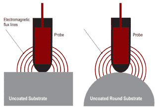
Speaking of distance, that’s what coating thickness gauges measure. Instruments use probes or sensors to generate a signal that travels through the coating to the substrate. As described by Newton, once the signal reaches the substrate a reaction occurs. The distance must be referenced from a starting point (that “zero reference” I pointed out earlier). That starting point needs to stay constant in order for the output or coating thickness value to be accurate and reliable. For example, if you set the starting point to a flat surface, and then change the rules by measuring on a radius, your output (thickness reading) will be skewed. This is easily shown in the illustration on the previous page. As you can see, the instrument is first set up on a flat surface, then used to measure a round part. The magnetic flux lines have increased their length of travel, but the increase is due to part geometry, not coating thickness. The gauge will display a positive value and indicate the presence of a coating even though no actual coating exists.
This example is rather obvious at this point, because we know there is no coating on the part surface. However, depending on the degree of the radius or surface geometry, it may not be so apparent that an error is occurring. What happens in these cases is that the instrument reading is overstating the true amount of coating present. This may prompt finishing line managers to dial down the amount of coating being applied to meet specifications. As a result, the managers have unknowingly applied less than the specified amount of coating—something that could obviously be detrimental to the product’s life, performance and/or that “first impression.”
And, the opposite scenario is possible. If you unknowingly picked up and started using a gauge that was previously set up on a curved surface and used it to measure a coating applied to a flat surface or an area with less profile, the results might lead you to believe you need to increase the amount of coating applied because the gauge is understating the true coating thickness.
So measurement accuracy depends greatly on the part surface profile used for initial gauge setup and the surface profile of the part being measured.
More Variables
Yet another variable that can impact thickness measurement accuracy is called edge effect. This occurs when measurements are taken too close to a part edge. The electromagnetic flux lines leak over the edge and, as a result, produce longer lines than if confined to the flat plane.
This is where it is important to know and respect the minimum area of measure for a particular probe to prevent this variable from skewing the equation. Probes and sensors are available that specifically address this variable, and accurate measurement is simply a matter of addressing and matching this requirement.
Another condition that exists is part surface profile, sometimes referred to as surface roughness. This can result from surface preparation in the form of, for example, shot blasting a surface. It can also be characteristic in the manufacturing process, such as with many castings.
Whatever the case, surface profile will affect the coating thickness value displayed. It will always cause the instrument to overstate the true thickness of the coating. The greater the degree of surface roughness, the more it will skew the reading. There is nothing in gauge manufacturers’ specifications or operating instructions that I am aware of that gives you a specific value or “compensator” to eliminate the effects of surface roughness. The reason is because surface roughness varies, and the degree to which it varies can only be determined by measurement.
The method required to determine the influence of surface roughness is to take an identical part and remove the roughness. Optimize the coating thickness testing gauge as you normally would, following the manufacturer’s instructions.
Next, take a series of readings and calculate the average of those readings to determine the average value and influence of the surface roughness. How many readings are required? The true answer is, you can stop taking readings when the reading you have just taken no longer significantly affects the average. Many gauges in the marketplace today have built-in statistics and can automatically do the calculations for you.
The average of your readings is the value and influence of the surface roughness compared directly with a smooth surface of the same part or component. This value or factor will then have to be subtracted from all coating thickness measurements taken over a coated surface of the same profile. If you don’t do this, you will be overstating the true thickness of the coating.
Keep in mind also that surface roughness typically will vary from part to part and in different areas of a part. For that reason, it is important to take a series of readings over an area and express the coating thickness value as a range incorporating one or two standard deviations into the expression. This approach results in a higher degree of certainty of the true thickness of the coating.
Generally speaking, slight part surface roughness, in combination with a thicker coating, is easier to control than, for example, significant surface roughness in combination with a thinner coating. In fact, if you do the math you can see that in certain situations surface roughness can completely wipe out any degree of measurement certainty if the coating being measured is very thin.
Some gauges in the market have a built-in capability to subtract a constant from calculated measurement values. This is a handy feature to have for quick spot checks, but it’s a single value and, as mentioned earlier, surface roughness will vary. It’s always best to express coating thickness value based on an average expanded by one or two standard deviations.
There are other factors that can influence the accuracy of a coating thickness value. However, these factors usually can all be minimized— if not completely eliminated—by following a few simple rules. Always optimize the gauge on an uncoated sample identical to the part or sample that will be coated. During optimization, try to replicate environmental conditions the gauge will experience at the point of measuring the coated part. While this may sound like a rather tedious and time-consuming exercise, there are devices in the marketplace that allow numerous gauge setups to be stored in memory and recalled when needed. Remember, any compromise made during gauge optimization will most likely affect the accuracy of the readings and performance of the coating.
If you find any of these points restricting and find yourself making compromises, chances are you are struggling to make your gauge fit your application. This can be costly. Do a little research and find the gauge that fits your application. Keep in mind that there is price and then there is cost. The last thing you want to do is jeopardize making a good first impression.
Related Content
Concrete Reinforced Bars Built to Last
Not all corrosion-resistant materials for infrastructure are created equally. Epoxy-coated steel rebar has advantages that other materials used to prevent corrosion do not.
Read MoreSurface Prep Solution for Rusted Rebar in Concrete
Julie Holmquist of Cortec Corporation discusses passivating corrosion on rebar and other reinforcing metals.
Read MoreCuring Oven Basics
Simply heating up the substrate does not cure the coating. There are many variables to consider when choosing the best cure oven for your application...
Read MoreRobots, AI and Superb BMW Surfaces
There isn’t an automotive paint shop in the world that doesn’t have post-paint inspection and defect processing. But BMW is doing this with levels of technology at a plant in Germany that exceed all other paint shops in the world.
Read MoreRead Next
Episode 45: An Interview with Chandler Mancuso, MacDermid Envio Solutions
Chandler Mancuso, technical director with MacDermid Envio discusses updating your wastewater treatment system and implementing materials recycling solutions to increase efficiencies, control costs and reduce environmental impact.
Read MoreA ‘Clean’ Agenda Offers Unique Presentations in Chicago
The 2024 Parts Cleaning Conference, co-located with the International Manufacturing Technology Show, includes presentations by several speakers who are new to the conference and topics that have not been covered in past editions of this event.
Read MoreDelivering Increased Benefits to Greenhouse Films
Baystar's Borstar technology is helping customers deliver better, more reliable production methods to greenhouse agriculture.
Read More


