Improvement of Corrosion Resistance of Magnesium by Anodizing in Alkaline Electrolytes
Results show that the novel organic additive reduced the sparking voltage and provided a relatively smoother surface.
Abstract
Anodization treatment of magnesium and its alloys is a useful surface treatment technique for forming protective coatings to improve their anti-corrosion properties, wear resistance and to enhance the adhesion capabilities of the surface. The anodic films formed on magnesium depend on the alloying constituents, anodizing process parameters and the electrolyte composition. To improve corrosion properties of anodic coatings on magnesium, environmentally-friendly, new aqueous alkaline electrolytes containing organic compounds, without toxic chromates and/or hazardous fluorides and phosphates, were investigated. The anodic film structure, component and surface morphology were analyzed using x-ray diffraction (XRD), scanning electron microscopy (SEM) and energy dispersive spectrometry (EDS). The anti-corrosion properties were investigated by electrochemical techniques. The results showed that the novel organic additive reduced the sparking voltage and provided a relatively smoother surface. Additionally, pores became considerably uniform in both size and distribution, due to the presence of the organic additive in the anodizing electrolyte. The anodic film produced with the organic additive exhibited the highest corrosion resistance for the AZ31B alloy.
Introduction
Magnesium, the eighth most abundant metal on earth, has seen an increase in applications in a variety of sectors ranging from aerospace, military, defense, and automotive to commercial mobile phones, sporting goods and handheld tools, owing to its high strength-to-weight ratio, machinability, thermal conductivity and weldability.1-4 However, the poor corrosion resistance of magnesium and its alloys has limited applications in corrosive environments.4-7
Improving corrosion performance involves a variety of finishing processes, including oil applications, wax coating, anodizing, electroplating, conversion coating, painting, etc. Metal finishers are often faced with challenges to tailor a better combination of these processes to enhance the product corrosion performance, considering various factors ranging from specific applications to environmental conditions. Although development of new and high purity magnesium alloys and novel surface modification techniques such as ion implantation and laser annealing have mitigated the corrosion problem, magnesium alloys still suffer from performance issues, especially under aggressive corrosive environments. High chemical reactivity, complex alloy microstructures, hazardous pretreatment procedures and recycling problems to an extent have discouraged many applications of magnesium.8-10
Among the typical surface modification techniques, conversion coating, electroplating with alloys like zinc, nickel and chromium and anodizing processes such as DOW 17, HAE, and Tagnite have become widely popular for the surface treatment of magnesium alloys. However, these techniques either resulted in a good paint base surface or incorporated harmful fluorides, chromates and phosphates. Although methods involving CVD, PVD, and plasma spray techniques have shown promise, they have not found a widespread application owing to the high startup and maintenance costs.
A majority of the magnesium alloys are either sand-cast or die-cast and hence are prone to microstructural inhomogeneities and surface imperfections, such as porosity and impurities. Magnesium and its alloys are also prone to galvanic corrosion and alloy dissolution owing to the lesser nobility of magnesium. Design of a process routine that results in an effective barrier to corrosion as well as wear would be ideal. The anodization process has been a widely accepted solution for surface protection of light metals, especially aluminum. The anodic coatings formed are not only wear resistant but also offer a porous template for further treatments like sealing, dyeing and painting.
Anodization of an alloy surface can be conducted via current or voltage control. Under voltage control, current drops as the oxide layer grows whereas under constant current, voltage increases with time. During the anodization of magnesium alloys, for any combination of bath composition and temperature, there is a maximum voltage that can be supported before breakdown occurs. Once the voltage crosses the dielectric breakdown voltage of the film previously formed, a spark is initiated, which with time turns into localized micro-arcs. Thus, various factors, including the mechanical finishing as a pretreatment, surface activation processes, a combination of bath composition and temperature could affect the coating formation and subsequently the performance of anodic coatings.
Huber, et al.,11 reported an interesting relationship between applied voltage and anodizing characteristics. When anodized in an alkaline electrolyte, a grey magnesium hydroxide layer formation was observed up to 3.0 V. A thicker version of this layer resulted between 3.0 and 20 V and an intensive sparking was observed above 50 V. Verdier, et al.,12 observed a combination of three different stages during the anodization of AM60 magnesium alloy under constant current. Voltage monitoring revealed a transition of traditional anodizing into spark anodizing and into a full arc process. Along with spark formation and voltage variations, oxygen evolution is another important phenomenon associated with magnesium anodizing. After analyzing the anodic behavior of AZ91D in a silicate bath, Shi, et al.,13 stated that oxygen evolution is a result of the thermal decomposition of localized sparking.
It has been reported that the anodic oxide coating may have a high porosity of up to 40%.14 As a result, the corrosion resistance of an oxide coating on magnesium alloy decreases with increasing porosity. Therefore, it is critical to reduce the coating porosity in order to modify the anti-corrosion performance. It is also important to develop an anodizing electrolyte, which does not contain any hazardous compounds like chromates, fluorides and phosphates, due to the environmental restrictions.
In this study, the anodizing process in an environmentally-friendly alkaline silicate-based electrolyte with and without a novel organic additive was investigated. The anodization process, anodic film morphology, structure and composition were examined. Electrochemical testing techniques were used to study the effect of the organic ingredient into the anti-corrosion properties of the produced anodic coatings.
Experimental
The formation of anodic films with the AZ31B magnesium alloy in alkaline silicate-based electrolytes was investigated. Magnesium samples (4 × 4 in.) were ground down using 150-grit SiC paper so that the surface was flat. Samples were degreased with acetone prior to anodization. The anodizing cell consisted of an agitated bath with two steel cathodes and anodization was conducted under constant current with a high voltage rectifier (70 A, 150 V) and the electrolyte temperature was maintained at 15 ± 5°C. Current and voltage transients were recorded by a commercially available AD-converter and a computer (JobPro). Anodizing was performed in concentrated alkaline solution containing silicates and an organic additive. The effect of the organic component on the anodic film was investigated by varying its concentration in the electrolyte.
Surface morphology of anodic films was observed using a Hitachi S-4700 cold-field emission Scanning Electron Microscope (SEM/EDS). The crystalline phase composition of the anodized samples was examined using a room temperature x-ray diffractometer (Philips PW 2273) with CuKα radiation.
The resultant anodic coating thickness was measured in accordance with ASTM B244 (Standard Test Method for Measurement of Thickness of Anodic Coatings on Aluminum and of Other Nonconductive Coatings on Nonmagnetic Basis Metals with Eddy-Current Instruments) using a pre-calibrated eddy current instrument. On each sample eighteen data points were obtained at different locations, and the average value was taken as the anodic film thickness.
The average surface roughness (Ra) of the anodic films was measured by a Surfometer, Series 400 (Precision Devices, Inc.). Potentiodynamic polarization measurements were carried out using a Gamry potentiostat and Gamry Echem Analyst software. A three-electrode configuration was employed: the anodized magnesium substrate as the working electrode, with a surface area of 3.0 cm2; a carbon rod as a counter electrode; and a saturated calomel electrode (SCE) as the reference electrode.
Results and Discussion
Characterization of the anodizing process
The effects of constant voltage control and constant current density control on the growth and formation of anodic coatings have been studied extensively. It has been shown that constant current density process has many advantages over traditional constant voltage controlled anodizing processes.15
It is virtually impossible for constant voltage control to produce the anodic coatings with consistent quality because of its inherent problems. In general, the growth rate of the anodic coating is found to be stable under constant current control, while the applied voltage is allowed to float, responding to the variations of physical, chemical and electrical factors such as surface area, contact resistance, solution resistance, etc., which frequently change from run to run, shift to shift, and day to day. Therefore, anodizing under the constant current was adopted in order to control and produce repeatable results.
The anodizing behavior of magnesium alloys depends on the combined effects of voltage variation and simultaneous sparking action. Anodic film growth is influenced by the relative concentrations of the chemical constituents of the electrolyte, current density or voltage levels, anodizing time, etc. It is well known that the electrolyte chemistry has a major influence on the anodizing process. The experiments were performed in an alkaline bath containing silicates at a fixed concentration and an organic component at varying concentrations.
Voltage-time response. The voltage transients for AZ31B magnesium alloy anodized in solutions with and without the organic additive are shown in Fig. 1. In both cases, the voltage curve shows three distinct regions based on the different rates of increasing voltage and the range of voltage oscillation:
- (Region I) a steep voltage rise up to 62 V at the beginning of the process
- (Region II) a slower rise with characteristic oscillations up to 90 V and
- (Region III) a constant voltage thereafter.
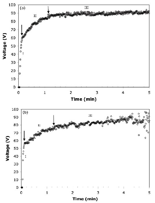
Figure 1 - Total voltage vs. time response for the anodization of the AZ31B alloy at 45 A/ft2: (a) no organic additive, (b) with organic additive.
In the first stage of anodizing, the voltage increased linearly until it reached the breakdown voltage of around 60 V for the AZ31B magnesium alloy. Beyond the breakdown voltage, intensive and white-colored sparking was observed at the surface in Region II. Regions I and II are also called “conventional anodization” and “dielectric breakdown,” respectively.16 The final stage shows that the voltage increased at a relatively slower rate and oscillated extensively within a larger range. In this final stage, sparks which formed on the surface of the alloy were large and orange in color and only appeared on specific sites on the surface. Similar voltage responses for the anodization of different magnesium alloys in highly alkaline solutions were reported by other research groups.17 The presence of the organic additive decreased the dielectric breakdown starting voltage levels from 62 V to 55 V and extended the duration of the second stage, as shown in Figs. 1(a) and (b).
The voltage fluctuation after sparking (Region II) has been reported to be the characteristic voltage transient for constant current anodizing of valve metals.18 It represents the formation of new anodic film, and the destruction of the existing film takes place simultaneously. The extensive voltage fluctuation possibly indicates the growth of the anodic film due to the competitive processes of the three important steps of (1) destruction of the film, (2) reparation of the film and (3) formation of new anodic film.19
In addition to the magnesium alloy, other valve metals, such as titanium, zirconium and niobium, also produce sparking during the anodizing process.20,21 Once the breakdown potential is reached, sparks are usually small in size, large in number and randomly distributed on the anode surface. However, toward the beginning of Region III, the number of sparks decreases and their kinetic velocity on the surface decreases, and as a result, they become visually detectable only at random locations on the magnesium surface.
The electrolyte temperature changes during anodizing owing to sparking on the anode surface and the IR drop of the solution. Sparking forms via localized high temperatures estimated to be greater than 1000°C on the anode-metal surface.22
Film growth. Figure 2 shows that the anodic film thickness depends on the anodizing time. It shows that the anodic film on the magnesium alloy grows at an almost uniform rate and the anodic film thickness increases with increasing anodization time under constant current density (45 A/ft2, 15 ± 5°C). However, the anodic film thickness reaches a plateau after 5.0 min and after 7.5 min of anodizing, the samples burned. Similar behavior was observed for electrolytes with and without the organic additive.
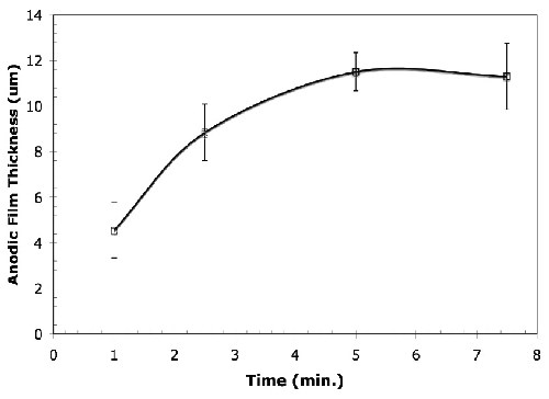
Figure 2 - Average thickness of anodic films formed in the alkaline-silicate electrolyte with the organic additive under the conditions of 45 A/ft2, 15 ± 5°C for anodizing times varying from 1.0 to 7.5 min. A similar trend was observed for the anodized samples prepared in the electrolyte without the organic additive.
Characterization of the Anodic Film
The anodic film produced in the alkaline-silicate based solution (with and without the organic additive) was relatively smooth and uniform silver grey in color. Figure 3 shows the characteristic surface micrographs of the anodic film on AZ31B formed under the conditions of 45 A/ft2 and 15 ± 5°C, for 5.0 min in the highly alkaline-silicate based electrolyte. Mechanically polished AZ31B magnesium alloy surface had deep scratches throughout the surface [Fig. 3(a)].
The presence of the organic additive led to a significant change in the macro- and microstructural morphologies of the anodic coating. The film formed in the additive-free electrolyte had an uneven surface with large pore size distribution [Fig. 3(b)]. On the other hand, with the addition of organic additive, even at very small amounts as low as 0.2 vol%, pores in the anodic coating became quite uniform in both size and distribution as shown in Figs. 3(c) and (d). Furthermore, the anodic coatings had a smaller number of pores in the micron or submicron range, with some microstructural flaws formed due to the presence of the organic additive in the anodizing electrolyte. These pores and flaws form because of the preferential growth of the film at microstructurally localized areas on the anodic surface related to the characteristic electrochemical heterogeneity of the surface. Further, the dielectric breakdown of the existing coating, randomly localized high current during sparking, and the trapping and the release of oxygen accompanied with water vapor may also have caused the pores and flaws in anodic coatings.
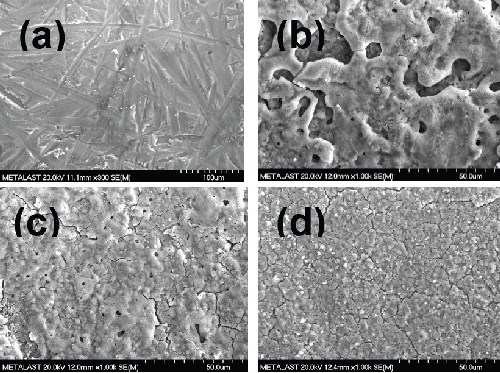
Figure 3 - Scanning electron micrographs of bare AZ31B magnesium (a) after mechanical finishing, (b) after 2.5 min anodizing without the additive, (c) after 2.5 min anodizing with 0.2 vol% additive and (d) after 2.5 min anodizing with 0.8 vol% additive at 45 A/ft2 and 15 ± 5°C.
X-ray diffraction (XRD) analysis was performed to investigate the changes in the composition of the oxide film formed in the alkaline-silicate electrolyte with the organic additive (Fig. 4). The diffraction pattern clearly shows that the films consist of MgO with trace amounts of magnesium impurities. Additionally, the anodic coatings formed in alkaline-silicate electrolyte with the organic additives contained very small amounts of MgSiO3 [Figs. 4(c) and (d)]. The presence of silicates in the anodic coatings was confirmed by EDS analysis.
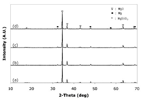
Figure 4 - X-ray diffraction patterns of anodic coatings on AZ31B magnesium formed in different electrolytes without the organic additive after (a) 2.5 min, (b) 5 min, (c) 7.5 min, and (d) with (d) 0.8 vol% organic additive at 45 A/ft2 and 15 ± 5°C.
The formation of the crystalline MgO phase can be explained by the simultaneous phase formation at the anodic film/electrolyte and magnesium substrate/film interfaces by the outward migration of Mg+2 ions from the substrate to the anodic coating/electrolyte interface and the inward migration of O-2 ions from the electrolyte to the substrate/coating interface, according to the following equation:23
Mg+2 + O-2→ MgO
Figure 5 shows the measured surface roughness values for the mechanically polished bare AZ31B magnesium alloy and the anodic coatings formed under the condition of 45 A/ft2 and 15 ± 5°C for 5.0 min in the alkaline-silicate solution with and without the organic additive at different concentration levels. The presence of the organic additive led to a significant reduction in the surface roughness from 2.522 μm (no additive) to 1.41 μm (0.2 vol% additive) and 0.91 μm (0.8 vol% additive).
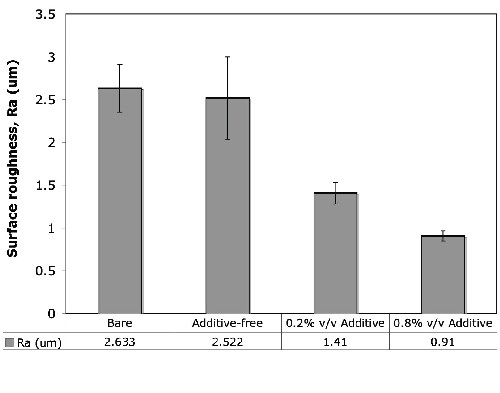
Figure 5 - Surface roughness values of bare and anodized AZ31B magnesium alloys anodized with and without the organic additive. The presence of the organic additive caused a significant reduction in the Ra values.
Corrosion Resistance
Electrochemical potentiodynamic polarization techniques were used to evaluate the corrosion resistance of bare and anodized AZ31B magnesium alloy with and without the anodic additive. Figure 6 shows the potentiodynamic polarization results for the bare and anodic coatings produced by different electrolytes. For the magnesium alloys anodized in electrolytes with the organic additive, the results show a relatively better quasi-passivation range in the anodic polarization curve. Additionally, the electrochemical parameters associated with the polarization curves are shown in Table 1. The electrochemical data presented in Table 1 shows that the corrosion protection of AZ31B magnesium alloy is increased significantly by anodizing with the organic additive.
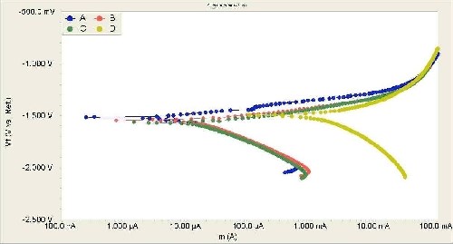
Figure 6 - Potentiodynamic polarization curves obtained in 3.5% NaCl solution at a scanning rate of 5 mV/sec: anodic coating produced in an electrolyte (a) with 0.8 vol% organic additive, with (b) 0.2 vol% organic additive, (c) without the organic additive and (d) bare AZ31B magnesium after mechanical polishing.
Table 1 - Electrochemical parameters associated with the polarization curves in Fig. 6.
|
Sample |
βa, V |
Βc, V |
icorr, A/cm2 |
Ecorr, V |
Rp, Ω |
Corrosion rate, mpy |
|
Additive (0.8 vol%) |
0.1473 |
0.2978 |
1.24 E-05 |
-1.51 |
103.6 |
8.392 |
|
Additive (0.2 vol%) |
0.1378 |
0.3429 |
2.85 E-05 |
-1.54 |
78.27 |
19.3 |
|
Additive (None) |
0.1441 |
0.3611 |
3.18 E-05 |
-1.56 |
19.25 |
21.56 |
|
Bare AZ31B |
0.2820 |
1.0390 |
6.52 E-03 |
-1.49 |
14.93 |
4.42 E+03 |
Electrochemical parameters related to the polarization curves (Fig. 6) show that the corrosion rate decreases approximately 200-fold and 500-fold for the anodized samples with the electrolyte containing an organic content of 0.2% vol% and 0.8% vol%, respectively. Similarly, the icorr values for the anodic coatings produced by the electrolyte containing 0.8% vol% organic additive were almost two orders of magnitude less than those for the bare AZ31 magnesium alloy. Furthermore, the polarization resistance (Rp) values also show that the anodic coatings produced in electrolytes with the organic additive have better anticorrosion properties in NaCl solutions.
The organic additive in the anodizing electrolyte reduced the pore size and the surface roughness of the anodic films. In general, an anodic coating with a smooth surface and smaller pores could provide superior anti-corrosion properties. Accordingly, an anodic oxide coating with lower roughness (Fig. 5) provides a relatively smooth surface layer for providing corrosion resistance against chloride attack.
Conclusions
During anodization of the AZ31B magnesium alloy in alkaline-silicate electrolyte solution, the addition of a proprietary organic additive resulted in the decrease of the breakdown potential. MgO was the main crystalline phase constituent of the AZ31B magnesium alloy along with Mg and MgSiO3 impurities. The presence of the organic component in the anodizing electrolyte led to a significant reduction in the pore size and provided uniform micron and submicron range pores homogeneously distributed throughout the surface. The roughness of the anodic oxide coating was reduced significantly due to the presence of the organic additive in the anodizing electrolyte. Furthermore, the anodic film containing the organic additive exhibited relatively better anti-corrosion properties. The novel organic additive provided a relatively smooth anodic film with small and uniform pore distribution, which provided a good barrier layer and effective corrosion protection.
Acknowledgements
Authors would like to thank Keith Johnson for his assistance in anodizing the samples. Byron Estes and Harish Bhatt are also acknowledged for their useful discussions.
References
1. S. Natarajan, et al., Corrosion Prevention and Control, 51 (4), 142 (2004).
2. M.M. Avedesian & H. Baker, Magnesium and Magnesium Alloys, ASM International, Materials Park, OH, 1999.
3. E.F. Emley, Principles of Magnesium Technology, Pergamon Press, New York, NY, 1966.
4. G. Song & A. Atrens, Adv. Eng. Mat., 5 (12), 837 (2003).
5. G. Song & A. Atrens, Adv. Eng. Mat., 1 (1), 11 (1999).
6. G. Song & A. Atrens, Adv. Eng. Mat., 9 (3), 177 (2007).
7. G. Song, Proc. International Conference on Magnesium - Science Technology and Applications, Trans Tech Publications, Stafa-Zurich, Switzerland, 2004; p. E01.
8. S.S. Cho, et al., J. Mater. Sci., 34 (17), 4311 (1999).
9. Y. Li, et al., J. Mater. Sci., 31 (15), 4017 (1996).
10. S. Ono & N. Masuko, Mater. Sci. Forum, Volumes 419-422, Magnesium Alloys 2003, Trans Tech Publications, Stafa-Zurich, Switzerland, 2003; p. 897.
11. K. Huber, J. Electrochem. Soc., 100 (8), 376 (1953).
12. S. Verdier, et al., Corros. Sci., 47 (6), 1429 (2004).
13. Z. Shi, G. Song & A. Atrens, Corros. Sci. (in press).
14. J.A. Curran & T.W. Clyne, Surf. Coat. Technol., 199 (2-3), 177 (2005).
15. L. Hao & B.R. Cheng, “Advantages of Constant Current Density Control over Constant Voltage Control in Aluminum Anodizing”, METALAST Report, Minden, NV, June 1998.
16. M.B.J.G. Feritas, C. Eiras & L.O.S. Bulhões, Corros. Sci., 46 (5), 1051 (2004).
17. D.P. Barbosa & G. Knörnschild, Surf. Coat. Technol., 203 (12), 1629 (2009).
18. O. Khaselev & J. Yahalom, Corros. Sci., 40 (7), 1149 (1998).
19. L. Chai, et al., Corros. Sci., 50 (12), 3274 (2008).
20. J. Yahalom & T.P. Hoar, Electrochim. Acta, 15 (6), 877 (1970).
21. G.C.Wood & C. Pearson, Corros. Sci., 7 (2), 119 (1967).
22. A.J. Zozulin & D.E. Bartak, Met. Fin., 92 (3), 39 (1994).
23. A. Bai & Z.J. Chen, Surf. Coat. Technol., 203 (14), 1956 (2009).
Related Content
NASF/AESF Foundation Research Project #123: Electrochemical Manufacturing for Energy Applications - 7th Quarterly Report
The NASF-AESF Foundation Research Board selected a project on electrodeposition toward developing low-cost and scalable manufacturing processes for hydrogen fuel cells and electrolysis cells for clean transportation and distributed power applications. In this period, we followed our work on 3D printing anode support for solid oxide fuel cells, SOFC (or cathode for solid oxide electrolyzers, SOEC) based on our designed optimization outlined in the previous report. We worked on optimizing the printing parameters, obtaining binder burn out and sintering profiles to obtain printed parts with desired geometry and properties.
Read MoreNASF/AESF Foundation Research Project #123: Electrochemical Manufacturing for Energy Applications – 4th and 5th Quarter Report
The NASF-AESF Foundation Research Board selected a project on electrodeposition toward developing low-cost and scalable manufacturing processes for hydrogen fuel cells and electrolysis cells for clean transportation and distributed power applications. During the reporting period, efforts were focused on planning the overall project work, with the eventual goal of manufacturing an improved design for a Solid oxide fuel cell anode supported flat tube (SOFC).
Read MoreNASF Foundation Research Project #123: Electrochemical Manufacturing for Energy Applications - 10th Quarterly Report
The NASF-AESF Foundation Research Board selected a project on electrodeposition toward developing low-cost and scalable manufacturing processes for hydrogen fuel cells and electrolysis cells for clean transportation and distributed power applications. In this period, we followed our work on 3D printing anode support for solid oxide fuel cells, focusing on the thermal shock properties of 3D printed yttria-stabilized zirconia (YSZ).
Read MoreNASF/AESF Foundation Research Project #123: Electrochemical Manufacturing for Energy Applications – 8th Quarterly Report
The NASF-AESF Foundation Research Board selected a project on electrodeposition toward developing low-cost and scalable manufacturing processes for hydrogen fuel cells and electrolysis cells for clean transportation and distributed power applications. This report covers the 8th quarter of work (October-December 2023, continuing work on 3D printing anode support for solid oxide fuel cells and electrolyzers. Work involved the effect of sintering temperature on the amount of porosity and grain size in 3D printed yttria-stabilized zirconia (YSZ).
Read MoreRead Next
Education Bringing Cleaning to Machining
Debuting new speakers and cleaning technology content during this half-day workshop co-located with IMTS 2024.
Read MoreA ‘Clean’ Agenda Offers Unique Presentations in Chicago
The 2024 Parts Cleaning Conference, co-located with the International Manufacturing Technology Show, includes presentations by several speakers who are new to the conference and topics that have not been covered in past editions of this event.
Read MoreDelivering Increased Benefits to Greenhouse Films
Baystar's Borstar technology is helping customers deliver better, more reliable production methods to greenhouse agriculture.
Read More


.jpg;maxWidth=600)


