Polarization - The 13th William Blum Lecture
This paper is a re-publication of the 13th William Blum Lecture, presented at the 59th AES Annual Convention in Cleveland, Ohio, on June 19, 1972. The theory of electrochemical polarization and its relation to what is seen in the plating tank were discussed.
by
Thomas Percy Hoar
Department of Metallurgy and Materials Science
University of Cambridge, England
Recipient of the 1971 William Blum
AES Scientific Achievement Award
Originally published as Plating, 61 (2), 35-42 (1974)
Editor’s Note: This paper is a re-publication of the 13th William Blum Lecture, presented at the 59th AES Annual Convention in Cleveland, on June 19, 1972. A printable PDF version is available by clicking HERE.
Introduction
When I was invited to give this lecture, I accepted with the greatest pleasure not only because of the honor done to me by your Society in making me the recipient of your most generous Award, but also because of the honor we can jointly do today to a man who, more than anyone else, put electroplating on the scientific map. William Blum had many predecessors and has had many more successors in the art and science of electrodeposition: important as their achievements have been, from Faraday and Elkington to Edwards, Brenner and a host of others, many of them here today, Blum's achievement was in one respect the most important of all. He turned what had been an art, a mystery, into a science worthy to be studied at the National Bureau of Standards. The past 100 years has seen the chemico-metallurgical arts turned one by one into sciences: that the change in the status of electroplating came a little late in the day is due in large part to the fact that Blum was born a little later than Bessemer, Thomas, Le Chatelier, Siemens, Osmond and Heycock.
In seeking a subject for this discourse I was mindful that it might be appropriate to bring before you some of the general ideas that the recrudescence of fundamental electrochemistry has thrown up and to relate them where possible to a few of the cathodic and anodic processes used in practical electrodeposition. "Polarization" suggested itself as an obvious broad title for a review of a field in which Blum himself did some of the pioneer cultivation from the electrodepositors' point of view.
"Polarization," in its simplest electrostatic sense, means "the separation of electric charge into + and - poles." We use the adjective "polarizable" in this sense in electrochemistry when we speak of an "easily polarizable ion," meaning an ion that under the influence of a strong electric field becomes dipolar by displacement of its electrons relative to its positive nucleus, and so readily adsorbable in the strong field at a metal/solution interface, or tightly held as a ligand by a charged cation; and also when we refer to a "perfectly polarizable electrode," meaning one that can sustain a considerable and varying degree of dipolar charge across the interface without passing any electric current. Generally, however, we use the term "polarization" in a looser but more specialized way to refer to the change of electric potential difference across an electrode interface (or across a thin film, or along a length of conductor) brought about by supplying (or subtracting) electric charge at one side (end) and not the other, so that the equilibrium initially existing across the interface (film, conductor) is disturbed and electric charge begins to pass through it.
That formal definition, of alarming length, includes all kinds of overpotential - "activation," "concentration" and the two sorts of "resistance" overpotential, as we 'Department of Metallurgy and Materials Science, University of Cambridge, England now know them conventionally. We shall fortunately not need to discuss semantics any further, and we shall proceed to look at our ideas of polarization or overpotential as they have developed historically through experiment.
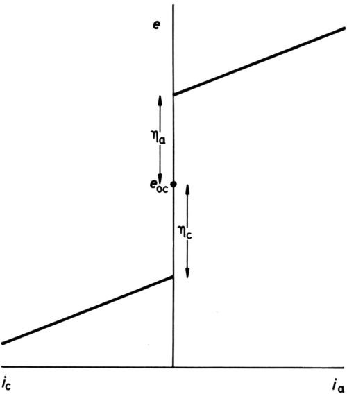
Figure 1 - Early definition of overpotential.
It has long been established that for any one electrode process, polarization is necessary to produce current. In early texts, it was stated that once an overpotential particular to an electrode had been reached, but not before, current began to pass. Diagrams such as Fig. 1 were drawn, showing an open-circuit electrode potential eoc, cathodic and anodic overpotentials ηc and ηa (when the process was known to proceed in either direction) and subsequent increase of current density i with potential more or less in accord with Ohm's law. With the coming of more sensitive ammeters, the diagram was modified to Fig. 2, although the small currents near to the open-circuit potential were thought of as "residual," while the overpotentials, rather uncertainly, were assigned to the point of the extrapolation of the apparently nearly straight potential/current-density (e/i) lines to i = 0. Tafel1 was among the first to discover that, for the hydrogen-evolution process at least, a large part of the cathodic e/i line was by no means linear but obeyed an equation:
, (1)
the celebrated "Tafel law." It was later found that the corresponding part of the anodic e/i line for a reaction that proceeds in the anodic direction also obeys a similar logarithmic equation:
. (2)
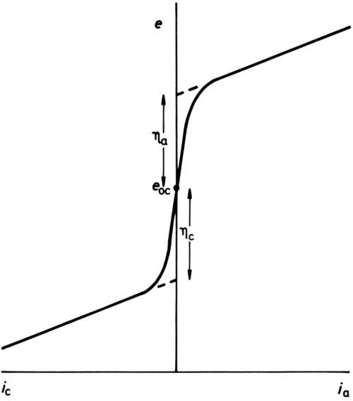
Figure 2 - Later definition of overpotential.
Of course, neither logarithmic equation could possibly represent the experimental e/i relationship when the experimentally measured current densities become small and finally zero at eoc, but the idea that the equilibrium at eoc is dynamic and not static, with finite values of ic and ia, was oddly slow to develop; it was not until 1924 that Butler2 made the first step towards the now conventional idea of the "exchange current" at eoc. The equating of ic = ia = io, the exchange current density, was probably first clearly stated by Erdey-Gruz and Volmer3 and by Hammett.4 Bowden and Rideal5 obtained ia for hydrogen on platinum by extrapolating the cathodic "Tafel line" to the known reversible open-circuit potential, and I6 obtained both the exchange current density and the reversible potential for the oxygen-electrode reaction O2 + 2H2O + 4e- ↔ 4OH- on platinum and gold by extrapolating both Tafel lines to their junction (Fig. 3).
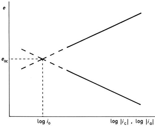
Figure 3 - Modern concept of activation overpotential showing Tafel lines, reversible potential erev, exchange current density io, anode overpotential ηa at potential e1 and cathode overpotential ηc at potential e2.
Formal derivations of the Tafel "law" from models were given by, among others, Butler,2,7 Gurney8 and Glasstone, Laidler and Eyring.9 I give below a simplified version,10 applicable to the dissolution or deposition of a metal under "activation" polarization11 into and from an aqueous solution.
“Activation” polarization
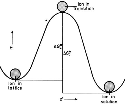
Figure 4 - Energy/distance diagram for electrode in equilibrium.
The metal ion in the lattice is in a position of minimum potential energy, or energy well, and in order to dissolve must pass into another energy well in the solution, probably an interstice in a “cage” of hydrating water molecules. To get there, it must receive extra energy to detach itself from the lattice and to squeeze between probably three water molecules to arrive in the cage. Conversely, a dissolved ion in a cage, in order to deposit, must mount the energy hump in the reverse direction (Fig. 4). The rates of dissolution and deposition are equal at the equilibrium potential eoc of the isolated metal on open-circuit, so we can write for them (in molecules/cmVsec),
(3)
where nl is the number of lattice points (per cm2) vibrating at frequency νl (per sec) that are in a position to dissolve when they get energy ΔGoa (cal per mole) and ns is the number of solution ions (per cm2) vibrating at frequency νs (per sec) that are in a position to deposit when they get energy ΔGoc (cal per mole).
The equal rates of dissolution and deposition are of course equivalent faradaically to the exchange current-density io, and we may simply write:
(4)
where Aa and Ac contain the constants converting number of molecules/cm2/sec to A/cm2, i.e.,
,
,
and F = 96500 C.
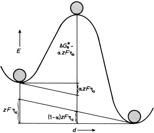
Figure 5 - Energy/distance diagram for electrode under anodic polarization.
To make ions dissolve, we polarize the electrode so that the metal becomes more positive to the solution than before, by removing negative charge from the metal - we make it the anode in a usual circuit, with overpotential ηa. This increases the energy of a lattice ion relative to the top of the energy hump so that it can more easily surmount it. If we assume the potential at any point between the lattice well and the solution well changes linearly with distance, the effect is as if the diagram of Fig 4 is tilted, as in Fig. 5. Now the height of the hump for dissolution is diminished by a fraction α of the total energy change zFηa, produced by the anode overpotential multiplied by the charge on the ion zF (per mole), so that the rate of dissolution is increased to
,
and conversely the rate of deposition is reduced to
.
Expressed as current densities, the rates are
(5)
or with (4)
, (6)
and
(7)
or with (4)
, , (8)
and evidently
ia >> ic for ηa > say 80 mV for z = 1 or 40 mV for z = 2.
If we can neglect ic at sufficiently high overpotential, then the experimentally measured anodic current density
ia (exp) = ia - ic ≈ ia,
and since
, , (6)
, (2)
the Tafel equation.
At low overpotentials, where we can neglect terms in and
and above in the expanded exponentials, the experimentally measured current density is
(9)
(10)
so that the part of the e/i (exp) curve near to the reversible potential is linear, following Ohm's law. The slope
(11)
may be called the "polarization resistance" [Note the rather different use of this term in corroding systems and other polyelectrodes.]
Obviously, between the linear and exponential parts of the e/i (exp) curve, there is a part that can be represented only by the full equation (9), which with a symmetrical energy hump, i.e., α = 0.5, gives
(12)
representing the whole e/i (exp) curve over its anodic branch, with
(13)
representing the cathodic branch.
Of course, real reactions are much less simple than the ideal
just considered. Successive reaction stages,16,17 adsorption effects18,19 and diffuse double-layer effects20 usually complicate the influence of polarization on current density, so that the simple equations (6) and (9) through (13) are rarely exactly followed, even when no side reactions intervene. Nonetheless, they surprisingly often give a fairly good representation of the experimental facts, at low and moderate polarizations and current densities.
Some simple modifications often required in rate equations such as (5) may be considered here. The number of lattice cations that are in a position to dissolve, nl, because they are at kink-sites or perhaps are adatoms, is the total number of surface lattice cations multiplied by a small fraction, θl. Similarly, the number of solution cations that are in a position to deposit, ns, is a function of the bulk solution concentration and also of any specific adsorption of the cations at the electrode interface: In the simplest cases, we may take the fraction of the interface covered with such ions, θS, as proportional to their bulk concentration. θl is thus contained in Aa and θS in Ac, and so long as each fraction remains constant, the form of the Tafel lines is unaffected. But if either is also a function of the potential difference across the interface, and therefore of the polarization ηa or ηc, then Aa in (5) and Ac in the corresponding cathode rate equation, or aa and ac in the Tafel forms, vary with the degree of polarization, so that linear Tafel lines are not found. Similarly, variation of θl and θS with temperature, and non-proportionality of θS with bulk concentration, lead to other deviations from the simple Tafel equations.
Inhibitors and stimulators
The familiar "addition agents" of electroplating - whether stress-relievers, brighteners or levelers - owe their actions to initial adsorption at the cathode surface.21-23 They are often said to "increase polarization" - a sloppy terminology, since what is meant is that their presence requires an increase in the polarization needed to maintain a given overall current density. It is better to define an inhibitor as a substance that reduces the overall current density at any given polarization.
The first and most obvious effect of an adsorbed inhibitor is to insulate the underlying metal atom(s) from either deposition or dissolution. This is a purely steric effect, and in some cases has been quantitatively demonstrated,24-26, the ratio
where θi is the fraction of the surface covered with inhibitor, giving a relation between θi and the solution concentration of inhibitor that obeys the Langmuir isotherm equation.
However, many substances give considerable inhibition even when θi is very small. This is a second, electrostatic, effect; the inhibitor, being a dipole or actual ion, reduces the overall rate of deposition (or dissolution) in its neighborhood by modifying the available electric field.
The steric and electrostatic effects need not act in the same direction; sometimes the electrostatic effect more than overcomes the steric, so that stimulation of the main electrode reaction occurs. Moreover, an adsorbed entity may in specific cases take part in the electrode reaction, acting as an intermediate catalyst. The most usual stimulators of metal electrode reactions are small, easily adsorbable anions, such as OH-27,28 and SH-,29 although certain adsorbable organic cations can sometimes stimulate the hydrogen-electrode reaction26,30 perhaps by acting as "bridges" for the transfer of protons between H3O+ ions and adsorbed H.
Stimulators have often been called "depolarizers" - a most unfortunate and confusing misnomer, stemming from the same illogical thinking that has produced the idea that inhibitors "increase polarization." A so-called "depolarized" nickel anode is, of course, one whose dissolution rate is stimulated at any given polarization by the presence of SH- ions derived from itself. Can we please have "stimulated" (or even "activated") anodes in the future?
Concentration polarization
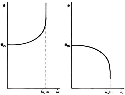
Figure 6 - Anodic and cathodic e/I curves showing current densities solely limited by mass transfer.
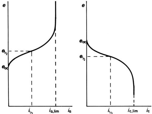
Figure 7 - Anodic and cathodic e/I curves showing current densities finally limited by mass transfer.
At high polarizations and current densities, new effects come into play, the first being the so-called "concentration" polarization. When an electrode reactant becomes in short supply because its mass transfer to the electrode surface cannot keep pace with the reaction rate, increase of polarization can no longer increase current density, which becomes limited by the limiting rate of mass transfer. For the simplest cases only diffusional transfer needs to be considered: this is true for electrode reactions in polarography, where the reactant is in small concentration as compared with other ions, and in oxygen-absorption corrosion, where it is uncharged. Then, calculation of the limiting rate can be done from a knowledge of diffusion constant and solution viscosity, e.g., by following the well-known equations of Ilkovic31 for the dropping mercury electrode and of Levich32 for the rotating disk. The e/i curve would take the general form of Fig. 6 if no activation polarization were present, but it always is, and the real curve is as in Fig. 7. Near the polarographic half-wave potential, e½ where i = ilim/2, there is an almost linear portion of the curve, of which the slope can be used to assess the polarographers' "irreversibility" of the reaction.33
A more interesting case can arise in some electroplating baths, where, owing to the high concentration of a depositing cation, no diffusion-limited current arises because of ion migration towards the cathode under the applied e.m.f.: the curve is then as shown in Fig. 8. Cases are also shown, both in plating and in polarography, where the depositing ion is in an anionic complex, and then increase of polarization leads to decrease of cathodic current, Fig. 9.
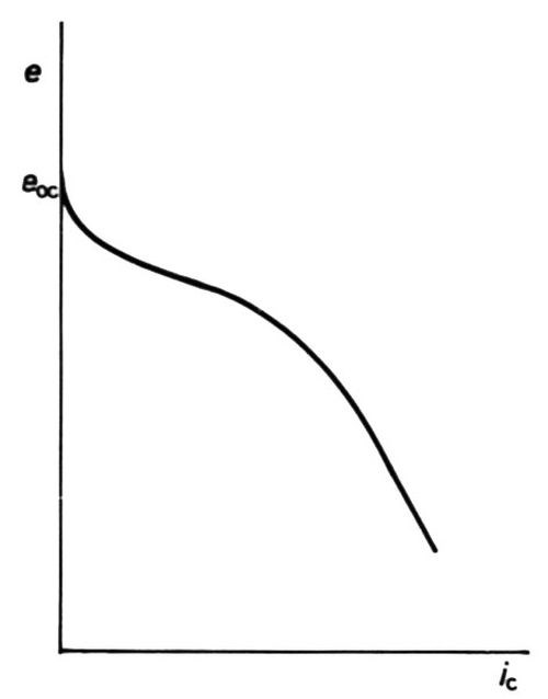
Figure 8 - Cathodic e/i curve showing partial limitation by mass transfer; migration of cations assists transfer.

Figure 9 - Cathodic e/i curve showing partial limitation by mass transfer; migration of anions hinders transfer.
Diffusion-limited current densities produced by high polarizations in plating baths are of no interest to platers because they invariably produce "burnt" deposits. The effect is, however, put to use in the electrolytic production of powders. Recent work34,35 suggests that at high cathodic polarization, electrons are present in such numbers or at such energy at the cathode, or both, that they can enter the solution (with sufficient probability) to neutralize cations before they arrive at the true metal/solution interface. Nonadherent powder particles result. The effect can be enhanced by the presence of molecules that adsorb on the metal surface35 at very high cathodic polarization: under some conditions, however, such adsorption produces so great a lowering of cathodic current density as to cause a form of "cathodic passivity,"36 Fig. 10.
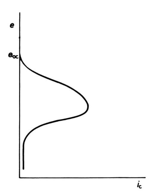
Figure 10 - Cathodic "passivation" (schematic, after Clarke and Bernie36).
Diffusion-limited current densities, are, however, frequently important in anodic polishing and leveling. They arise especially in the anion-concentrated, water-poor solutions so often found to give the best polishing or leveling,37 probably because the water molecules needed to hydrate the dissolving cations have a limiting diffusion rate towards the anode. The experimentally found limiting current densities increase with solution flow-rate past the anode, except when other limiting factors associated with the solid films on electropolishing anodes38,39 become important.40,41
Limiting maximum of activation polarization
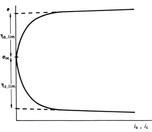
Figure 11 - Anodic and cathodic e/i curves for Watts nickel bath (schematic, after Wesley42).
Yet another effect of high polarization, although experimentally easily demonstrated in molten salt baths and in certain plating baths, where, even at high polarization, concentration effects are small, does not seem to have been hitherto explicitly explained. The e/i curves take the form42,43 of Fig. 11, showing activation polarization followed by an apparently linear section with a low de/di slope. The linear section at high polarizations seems to depend only on the IR drop between the reference electrode (with or without a Luggin capillary) and the electrode being examined. A reasonable explanation is, I think, that high polarization has so "tilted" the activation energy hump that no further reduction in ΔGoa (or ΔGoc) is possible - the thermal activation energy is abolished by the electrical energy. If this is correct, extrapolation of the linear parts of the e/i curves to i = 0, ηa = ηa, lim, ηc = ηc, lim should lead to an estimate of ΔGoa and ΔGoc, since
Applied to some results quoted by Wesley42 for a conventional Watts nickel bath, in which ηa, lim appears to be 0.415 V, and ηc, lim 0.225 V, and for which we assume α = 0.5, z = 2, this gives 9.6 kcal/mol,
ΔGoa = 9.6 kcal/mol; ΔGoc = 5.2 kcal/mol
An experimental estimation of the apparent enthalpy of activation ΔGoa,app from the temperature coefficient if io for nickel dissolution in sulfate solutions44,45 gave 10.6 kcal/mol. The difference
leads to ca + 3.3 cal/deg/mol for ΔSoa, a not unreasonable result indicating a fair degree of disordering in the formation of the transition state for dissolution from the highly ordered lattice. The very crude calculation could of course be refined to take care of intermediate stages and so forth; in particular, the value of ΔHoa, app may well contain a positive ΔH for solid à kink-site atom that would make the true ΔHoa for dissolution a good deal smaller than the "apparent" experimental value of 10.6 kcal/mol.
The rather similar extrapolation of E/I curves for molten salt decomposition (where E is the cell emf and I the cell current) has been used to give a so-called "decomposition voltage." This is always greater than the thermodynamic value. The difference may well be equivalent to the sum of the cathodic and anodic thermal ΔGo’s.
Figure 12 is a general scheme of the various parts of a cathodic e/i curve just discussed. Of course, at lower concentrations of the cathodic reactant, the mass-transfer limitation occurs at smaller ηc, as in polarographic analysis.
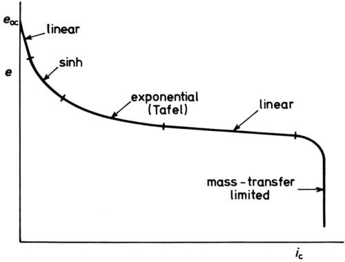
Figure 12 - Five parts of a cathodic e/i curve (schematic).
“Resistance” polarization
When the product of an electrode reaction - either cathodic or anodic - is a sparingly soluble solid that adheres as a continuous film to the electrode, very considerable polarization may have to be applied to produce substantial current densities. If the product increases in thickness with the passage of charge, the polarization must be increased if the current density is to be maintained: at constant polarization, the current density of course diminishes with time. The phenomena of anodic passivation and, especially, anodic film formation illustrate this so-called "resistance polarization" - which is the polarization required to overcome the electrical resistance, ohmic or otherwise, of a poorly-conducting film.
It is likely that the formation of the first monolayer of solid oxide on a metal anode is kinetically an easy process, if the thermodynamic conditions for its formation are met.37,46,47 Metal cations emerging from the lattice do not have to squeeze into a solvation cage, but merely to emerge into gaps in a first-formed partial layer of negative oxide anions - literally an attractive process for the positive cations. Further emergence to form the second layer is likely to be much more difficult, first because the attraction by the next layer of anions will be very much less owing to their greater distance from the metal lattice - in other words, the polarization, which is the overpotential between the metal and the solution, is now applied over a greater distance, so that the electrical field is reduced; and secondly, because solid-state ion migration is now involved. If the current density is to be kept constant as the film thickens by ionic migration, the polarization must be increased so that the field through which the ions move is constant - i.e., the ratio V/y where V is the potential difference across the film thickness y, must be constant. To achieve this, a "resistance polarization" depending on y is required, over and above any other overpotential.
It was shown experimentally by Gunterschulze and Betz48 that for the "barrier-layer" alumina films formed anodically on aluminum in solutions that do not allow any solution of the alumina
(14)
where A and B are constants and F is the field across the film. Analogous results are obtained on tantalum, niobium and many other similar metals.49 The form of (14) recalls (6) and the Tafel equation: by using a model similar to that of Figs. 4 and 5, Verwey50 obtained
(15)
where a is the distance between energy wells in the oxide, in apparent agreement with the experimental relation (14). Mott and Cabrera,51 considering the major barrier to ion movement to be the first "jump", from the metal to the oxide, obtained
(16)
where b is the distance of that jump. Dewald,52 pointing out that the temperature dependence of i explicit in (15) and (16) is often not experimentally observed, proposed a composite model based on the Verwey and the Mott-Cabrera models, in which both barriers are considered; Vermilyea,53 Young49 and others noted that, in a growing film where cations and anions have different mobilities, the influence of evanescent space charge should be taken into account; Yahalom and I,54 noting the large values of a (or b) that are needed to fit experimental results, revived a suggestion of Maurer55 that the jump distances in these glassy films may well be variable and large; and many other suggested refinements of the general theory have been made. Here we point out merely that the "resistance polarization" required to grow anodic oxide films can be very large, up to several hundred V as compared with the several hundred mV that is about the limit of activation polarization on film-free surfaces.
If, however, the solid film formed on an anode is a good conductor of electrons, then it is not possible to set up a high polarization across it and so grow thick films by ionic migration, because anodic reactions such as oxidation of solution entities - water or anions - can proceed at quite low potentials on the surface of the very thin oxide film with passage of electrons through it to the metal.46 The metal remains "passive."37 "Resistance polarization" is still required, but in small amount. Furthermore, if the solid film dissolves as fast as it forms, as in electrobrightening, it also remains thin, and having also a relatively low specific resistance,56 does not involve particularly high resistance polarization even for quite large current densities.
Resistance polarization is also required to overcome the effect of films in reducing current densities on cathodes. Such films may be inorganic - e.g., calcareous films formed in hard waters - or organic - e.g., electrophoretically deposited paints. Of course, the actual film-forming phenomenon is just as desirable as it may well be in the anodic case, and the polarization required to overcome the film resistance is applied only to the extent needed to thicken the film to its final state.
A different phenomenon, sometimes called "resistance polarization" or "resistance overpotential," is really a pseudo-effect so far as electrodes are concerned. It is the potential difference between the point in the solution where a measuring half-cell is inserted and a point just outside the solid electrode itself, needed to sustain the current through the solution. Historically, the Luggin probe57 and more recently the Piontelli back-side capillary58 have been used to reduce this potential difference to negligible amounts, since in most electrode investigations it is a trivial phenomenon not worth studying. However, the phenomenon may be of importance in practical situations where probes are not easy to use or when high-resistance electrolyte solutions are concerned, and also when electrodes at very high current density are being examined, as in the "limiting activation polarization" condition discussed above.
Power losses due to polarization
Polarization of an electrode, necessary to give rise to a desired current density of any cathodic or anodic reaction, always leads to a degradation of electrical energy to heat, in amount zFη per g-mol of substance reduced or oxidized at overpotential η. The power loss for total current I is of course iη, and this is additional to the I2R loss in the body of the cell. For this reason, an aim in electrowinning and especially in electrorefining is to optimize conditions so that the minimum polarization is required.
The situation is rather different in electroplating and electroforming, where power losses are relatively less uneconomic in view of the nature of the products produced. Consequently, if there is technical advantage to be had from increasing the polarization required to produce a given amount and rate of deposition of product, such increase is usually justifiable. The use of addition agents in plating baths to give stress reduction, leveling and brightening in deposits involves increase of polarization in each case to give the same over-all current density, and this is entirely acceptable.
Similarly, the large power loss (and heating) that occurs through the resistance polarization necessary to form films of low conductivity is quite acceptable as a necessary concomitant of the processes.
Making good use of polarization
It is fitting to allude to another example of the benefits of polarization by reference to throwing power, as it may be estimated by the Haring-Blum cell.59 Analysis of the electrical circuit of such a cell leads very simply60 to the relation
(17)
where I1 is the current at the near cathode, I2 that at the far cathode, R1 the resistance of the short path, R2 that of the long path, Δe the difference (e2-e1) in cathode potential between the far cathode (at e2) and the near cathode (at e1) and ΔI the difference in current at the near cathode and the far cathode (Fig. 13). Evidently, if Δe/ΔI =0, I2/I1 = R1/R2 and the throwing power is zero. If Δe/ΔI = ∞, I2/I1 = 1 and the throwing power is perfect. Now Δe/ΔI is the average slope (of course negative) of the cathode e/I curve, and evidently this must be large compared with the solution resistance to give good throw. Put in another way, the "electrode resistance" should be high compared to the solution resistance. This is by no means always easy to achieve in cathodic electrodeposition of metals, but "resistance polarization" in the cataphoretic deposition of nonmetals such as paints and, especially, in the production of anodic films on aluminum and in the anodic protection of stainless steels, gives these processes exceptional throwing power.
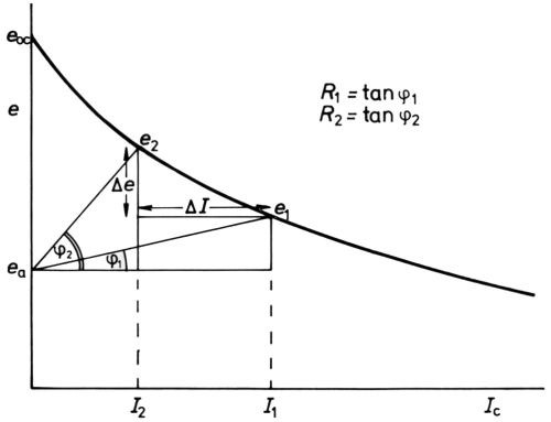
Figure 13 - Analysis of potentials and current in the Haring-Blum cell59 (after Hoar and Agar60).
An even more illuminating result comes from putting (17) into specific form by transforming it into terms of current density i (A/cm2) and specific conductivity κ (mho.cm). It becomes60
(18)
where l1, l2 are the lengths in cm of the two sides of the Haring-Blum cell. Δe/ΔI is the average slope of the e/i polarization curve specific for the plating bath: and we note that as well as depending on a steep e/i curve, good throw requires high specific conductivity of the bath and small size. In an unavoidably large plant, the best throw obtainable is to be had from high conductivity baths and steep cathodic polarization characteristics. We may note also that laboratory determinations of throwing power cannot be translated directly to practical baths unless the appropriate linear dimensions of the laboratory cell and the practical bath are about the same: thus ordinary laboratory determinations are liable to be too optimistic for large practical baths, (e.g., those nickel-plating bumper-bars) and too pessimistic for small ones (e.g., those gold-plating very small parts). Exactly the same size considerations apply to the Hull cell and to other throwing-power cells, and indeed, to "model" electrochemical cells of every kind.61
The general importance of polarization
The requirement of high polarization to give even small current densities in the cathodic reduction of oxygen is adventitiously of great material benefit to us; were this polarization requirement low, all our metals would perform like short-circuited Grove cells and disappear rapidly in any electrolytic environment. So relieved was I by my realization, nearly 40 years ago, of this (rather obvious) truth that I wrote6 with the smugness of youth, "Thus, while the slowness of the oxygen hydroxyl ion reaction has the unfortunate academic consequence that the reversible oxygen electrode cannot be prepared, it nevertheless has the much more important practical effect of rendering the corrosion of metals in aerated electrolytes comparatively slow."
Now at just about that time, Bacon, unknown to me, was beginning his search for a practical fuel cell62 - which, after years of intensive development, much of it aimed at reducing the polarization required for the rapid cathodic reduction of oxygen, has been several times successfully round and on the moon in the Gemini and Apollo projects. Somewhere in the 1950s I think I atoned a little for my earlier statement, when I had thankfully and smugly accepted the oxygen cathode as a sluggish beast - almost a non-starter - and for my 1950 skepticism of the fuel-cell project. Tom Bacon, then working in our laboratory, put his head round my door one day and mildly complained, "If my nickel electrodes are coarsely porous the caustic potash goes through, and if the pores are fine the gas won't." I replied, very off-handedly because I was teaching, "Oh, get them to make them coarse on one side and fine on the other" - and Bacon (no metallurgist, but an inspired engineer) went off and got his biporous electrodes successfully into action. So I may have made a tiny contribution towards accelerating the reaction O2 + 2H2O + 4 e- 4OH- where this was needed, as well as some others towards retarding it in corrosion situations. The oxygen electrode is in fact one of the most complex electrochemical systems,63 displaying nearly all the polarization phenomena that electrochemists, "pure" and "applied," are interested in: electroplaters, mainly concerned with the somewhat simpler metallic systems, may feel thankful that they can usually leave oxygen to the attention of the fuel-cell and corrosion people!
But let me end on a serious note: electroplating and the allied processes are no longer "arts;" they are complex applied science, and as Blum realized more than half a century ago, susceptible of technological and economic improvement only by constant scientific study in all their varied fields. Of these fields, that of "polarization" is among the more important.
References
1. J. Tafel, Z. Phys. Chem., 50, 641 (1905).
2. J.A.A. Butler, Trans. Faraday Soc., 19, 729 (1924).
3. T. Erdey-Gruz and M. Volmer, Z. Phys. Chem., A150, 203 (1930).
4. L.P. Hamniett, Trans. Faraday Soc., 29, 770 (1933).
5. F.P. Bowden and E.K. Rideal, Proc. Roy. Soc., A120, 59 (1928).
6. T.P. Hoar, ibid., A142, 628 (1933).
7. J.A.V. Butler, ibid., A157, 42,3 (1936).
8. R.W. Gurney, ibid., A134, 137 (1932).
9. S. Glasstone, K. Laidler and H. Eyring, The Theory of Rate Processes, New York-London, McGraw-Hill, 1941; p. 575.
10. T. P. Hoar in Modern Aspects of Electrochemistry, ed. J. O'M. Bockris, No. 2, London, Butterworths, 1959; p. 262.
11. F.P. Bowden and J.N. Agar, Ann. Rep. Chem. Soc., 35, 90 (1938).
12. K.F. Bonhoeffer and W. Jena, Z. Elektrochem., 59, 151 (1951).
13. M. Stern and A.L. Geary, J. Electrochem. Soc., 104, 56 (1957).
14. M.Prazak and K. Barton, Corros. Set., 7, 159 (1967).
15. T.P. Hoar, ibid., 7, 455 (1967).
16. V.V. Losev, in Modern Aspects of Electrochemistry, ed. B. E. Conway and J. O'M. Bockris, No. 7, New York, Plenum, 1972; p. 314.
17. M. Devanathan, Electrochim. Acta, 17, 1683 (1972).
18. A.N. Frumkin, in Advances in Electrochemistry and Electrochemical Engineering, ed. P. Delahay and C.V.Y. Tobias, Vol. 1, p. 65; Vol. 3, p. 287, New York, Interscience, 1961, 1963.
19. R. Parsons, in ref. 18, Vol. 1, p. 1.
20. A.N. Frumkin, Z. Phys. Chem., A164, 121 (1933).
21. T P. Hoar and D.J. Arrowsmith, Trans. Inst. Metal Finishing, 36, 1 (1958).
22. T. P. Hoar, J. Electrodepositors Tech. Soc., 29, 302 (1953).
23. S. A. W atson and J. Edwards, Trans. Inst. Metal Finishing, 34, 167 (1957).
24. T. P. Hoar and R. D. Holliday, J. Appl. Chem., 3, 502 (1953).
25. J. Elze and H. Fischer, J. Electrochem. Soc., 99, 259 (1952).
26. T. P. Hoar and R. P. Khera, in European Symposium on Inhibitors of Corrosion, Italy, University of Ferrara, 1961; p. 73.
27. J. O'M. Bockris, D. Drazic and A.R. Despic, Electrochim. Acta, 4, .325 (1961).
28. K.E. Heusler, Z. Elektrochem., 62, 582 (1958).
29. T.P. Hoar and D. Havenhand, J. Iron Steel Inst., 133, 239P (1936).
30. B.E. Conway, J. O'M. Bockris and R. Lovrecek, Proc. 6th Meeting CITCE, Poitiers 1954, London, Butterworths, 1956; p. 207.
31. D. Ilkovic, Coll. Czech. Chem. Commun., 6, 498 (1934); J. Chim. Phys., 35, 129 (1938).
32. V.G. Levich, Physicochemical Hydrodynamics, Englewood Cliffs, N.J., Prentice-Hall, 1962.
33. J.B. Headridge, Electrochemical Techniques for Inorganic Chemistry, London and New York, Academic Press, 1965; p. 25.
34. A. Calasaru, Electrochim. Acta, 12, 1507 (1967).
35. A. Calasaru, ibid., 18, in press.
36. M. Clarke and J.A. Bernie, ibid., 12, 295 (1967).
37. T.P. Hoar, Corros. Sci., 7, 341 (1967).
38. T.P. Hoar and J.A.S. Mowat, Nature, London, 165, 64 (1950).
39. T.P. Hoar and T.W. Farthing, ibid., 169, 324 (1952).
40. T.P. Hoar and G.P. Rothwell, Electrochim. Acta, 9, 135 (1964).
41. G.P. Rothwell and T.P. Hoar, ibid., 10, 493 (1965).
42. W.A. Wesley, Trans. Inst. Metal Finishing, 33, 452 (1956).
43. J. O'M. Bockris and S. Srinivasan, Fuel Cells - Their Electrochemistry, New York, McGraw-Hill, 1969; pp. 166, 182.
44. T.P. Hoar, Trans. Inst. Metal Finishing, 42, 166 (1962).
45. G.H. Notman, Thesis, Cambridge (1961).
46. T.P. Hoar, Proc. 3rd Meeting CITCE, Berne 1951, Manfredi, Milan, 1952; p. 146.
47. T.P. Hoar, J. Electrochem. Soc., 117, 17C (1970).
48. A. Gunterschultze and H. Betz, Z. Phys., 92, 367 (1934).
49. L. Young, Anodic Oxide Films, London and New York, Academic Press, 1961.
50. E.J.W. Verwey, Physica, 2, 1059 (1935).
51. N. Cabrera and N.F. Mott, Rep. Phys., 12, 163 (1948-49).
52. J.F. Dewald, J. Electrochem. Soc., 102, 1 (1955).
53. D.A. Vermilyea, ibid., 102, 655 (1955); 104, 140 (1957).
54. J. Yahalom and T.P. Hoar, Electrochim. Acta, 15, 877 (1970).
55. R.J. Maurer, J. Chem. Phys., 9, 579 (1941).
56. M. Cole and T.P. Hoar, Proc. 8th Meeting CITCE, Madrid 1956, London, Butterworths, 1958; p. 158.
57. H. Luggin, cited by F. Haber, Z. Phys. Chem., 32, 208 (1900).
58. R. Piontelli and G. Bianchi, Proc. 2nd Meeting CITCE, Milano 1950, Milano, Tamburini, 1951; p. 379.
59. H.E. Haring and W. Blum, Trans. Am. Electrochem. Soc., 44, .313 (1923).
60. T.P. Hoar and J.N. Agar, Discuss. Faraday Soc., 1, 162 (1947).
61. J.N. Agar and T.P. Hoar, ibid., 1, 158 (1947).
62. F.T. Bacon, Electrochim. Acta, 14, 569 (1969).
63. J.P. Hoare, The Electrochemistry of Oxygen, New York, Wiley-Interscience, 1968.
About the author
This piece was written at the time Dr. Hoar was announced as the recipient of the 1971 Scientific Achievement Award:

Thomas Percy Hoar was born in Rochester, England on November 16, 1907. His early education was obtained in that city at Sir Joseph Williamson's Mathematical School. He later attended Sidney Sussex College, Cambridge, and was awarded his Ph.D. degree from the University of Cambridge in 1933, for studies of the corrosion of iron and of the oxygen electrode. In 1958, he received the Doctor of Science degree.
His paper, co-authored with Dr. U.R. Evans in 1932, on the velocity of corrosion was among the first to correlate corrosion rate quantitatively with measured electrochemical reaction rates. He performed important studies for the International Tin Research and Development Council. In the early 1940s, his studies on inhibiting corrosion, mainly by the use of sodium nitrite, contributed important knowledge. In 1946, Dr. Hoar was appointed lecturer in the Department of Metallurgy at the University of Cambridge, and Reader in Chemical Metallurgy in 1966.
He has been editor-in-chief of Electrochimica Acta from the time of its inception in 1959. He was instrumental in the founding and was second president of the International Committee for Electrochemical Thermodynamics and Kinetics. He has served on the editorial board of Corrosion Science.
Dr. Hoar is a past president of the Institute of Metal Finishing of England, and has been president of the Corrosion and Protection Association in the United Kingdom. The IMF presented him with the Hothersall medal in 1962.
He is a member of the Faraday Society, Society of the Chemical Industry, Institute of Metals, Iron and Steel Institute and The Electrochemical Society, from which he received the Palladium Medal in 1969. He is a Fellow of the Royal Institute of Chemistry. He has served as president of the Institute of Corrosion Technology, and chairman of a committee of the British Ministry of Technology on studying the cost of corrosion and protection in the UK.
He was host organizer of the Third International Conference on the Passivity of Metals at Cambridge, England in July 1970. A prolific author, he has published more than 100 papers. Dr. Hoar, with his wife, has visited the United States many times. He has lectured here, in Australia, Chile, New Zealand, Argentina, and on the European Continent. A gifted speaker, Dr. Hoar will deliver the William Blum Lecture at the Opening Session of the 1972 Convention in Cleveland, Ohio on Monday morning, June 19.
Related Content
Successful South African Plater Beating the Odds
Remaining focused on quality and reliability, Team Plating Works stays profitable in a volatile and challenging economy.
Read MorePossibilities From Electroplating 3D Printed Plastic Parts
Adding layers of nickel or copper to 3D printed polymer can impart desired properties such as electrical conductivity, EMI shielding, abrasion resistance and improved strength — approaching and even exceeding 3D printed metal, according to RePliForm.
Read MoreNanotechnology Start-up Develops Gold Plating Replacement
Ag-Nano System LLC introduces a new method of electroplating based on golden silver nanoparticles aimed at replacing gold plating used in electrical circuits.
Read MoreProducts Finishing Reveals 2024 Qualifying Top Shops
PF reveals the qualifying shops in its annual Top Shops Benchmarking Survey — a program designed to offer shops insights into their overall performance in the industry.
Read MoreRead Next
Episode 45: An Interview with Chandler Mancuso, MacDermid Envio Solutions
Chandler Mancuso, technical director with MacDermid Envio discusses updating your wastewater treatment system and implementing materials recycling solutions to increase efficiencies, control costs and reduce environmental impact.
Read MoreDelivering Increased Benefits to Greenhouse Films
Baystar's Borstar technology is helping customers deliver better, more reliable production methods to greenhouse agriculture.
Read MoreA ‘Clean’ Agenda Offers Unique Presentations in Chicago
The 2024 Parts Cleaning Conference, co-located with the International Manufacturing Technology Show, includes presentations by several speakers who are new to the conference and topics that have not been covered in past editions of this event.
Read More


