Some Practical and Theoretical Considerations of Corrosion and the Role of Chromium - The 12th William Blum Lecture
This paper is a re-publication of the 12th William Blum Lecture, presented at the 58th AES Annual Convention in Buffalo, New York, on June 14, 1971. The corrosion of plated coatings under varying environmental conditions, including the effect of polarity, porosity, combination of plate, as well as thickness and other factors on the durability of the plated product is covered.
by
Jesse E. Stareck
Recipient of the 1970 William Blum
AES Scientific Achievement Award
Editor’s Note: Originally published as Plating, 59 (4), 303-308 (1971), this paper is a re-publication of the 12th William Blum Lecture, presented at the 58th AES Annual Convention in Buffalo, New York, on June 14, 1971. A printable PDF version is available by clicking HERE.
ABSTRACT
The corrosion of plated coatings under varying environmental conditions is discussed. The effect of polarity, porosity, combination of plate, as well as thickness and other factors on the durability of the plated product is described and touched on more fundamentally. Less well understood is the undermining effect that often occurs during plating, particularly of such metals as magnesium, aluminum, zinc and even steel. Some theoretical aspects are developed and presented.
I wish to take this opportunity to thank the Society I for this signal honor. I know you had my research team in mind, and much credit must go to them and to my loyal friends and associates in the plating industry, who over the years have contributed so much that made this occasion possible.
Also, I think it fitting at this time to mention my first contact with Dr. Blum. It was back in the depression days of 1933, almost 40 years ago. I sought his advice in connection with color plating, which I came upon in the process of working out my doctoral thesis.
If I may digress a bit here, this is how it happened. After considerable searching for a suitable topic, I finally concluded that an alkaline divalent copper plating bath should make an interesting subject for a thesis. A readily available complexing agent at the time was Fehling's solution (an alkaline copper tartrate reagent). I ran some polarograms on it and kept getting an unexpected break in the cathode curve at low voltages. In trying to determine the cause, I examined the cathode film from time to time. To my great surprise a different color was obtained every time I looked at it.
As it turned out, the colored deposit was cuprous oxide, plating out at the cathode just like a metal. Needless to say, my attention was diverted from the copper project to one of color plating. It was not until later, in 1935, that a suitable alkaline complexing agent was finally found for the copper project, namely, pyrophosphate. This time, in reverse, it was an outgrowth of the color plating (Electrocolor) research carried out for United Chromium.
The initial color plating investigation, however, proved to be a fascinating topic for a thesis. As the research phase neared completion, it was in an effort to find out whether color plating might be novel or useful that my professor at the University of Kansas, the late Dr. Robert Taft, suggested that I write to Dr. Blum at the National Bureau of Standards to seek his advice and counsel. I still have his kind reply.
Over the years we had many other associations, particularly in connection with the various corrosion projects that were being carried out by the Bureau of Standards, the AES and ASTM. In following these programs, I became interested in the unexplained anomalies that often showed up at the various corrosion sites.
I should like to review at this time some of the more interesting situations that came to light, and some of their interpretations and applications, particularly with respect to composite electrodeposited coatings. Before doing this, however, it might be instructive to review briefly some of the pertinent factors that have been established with respect to the corrosion behavior of electrodeposited coatings.
It has long been recognized, for example, that the position of the plated metal in the galvanic series is an important factor in determining protection. Figure 1 shows the relative positions of the more common metals and alloys used by the plating industry, and some of the cathodic displacements that result from natural passivation in the atmosphere. The scale, however, is not changed appreciably in the salt spray, inasmuch as the passivating agent (oxygen) is still the same. The salt mainly increases the cell conductivity and shortens the time to corrosion failure.
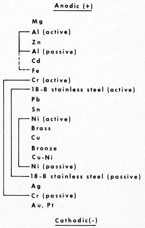
Figure 1 - Galvanic series (atmosphere) for metals common in electroplating.
Metals higher in the scale (active) generally give cathodic protection to those lower. However, some metals are more prone to passivation than others, and as a result strongly shift in potential to more cathodic positions. Thus, aluminum in air becomes cathodic to zinc, and sometimes even to steel.
Of particular interest is the pronounced shift in the cathodic direction of chromium, nickel and stainless steel, as they change from the active to the passive state. Chromium shows the greatest shift, and this has both good and bad implications. It is good because passive chromium is a poor conductor and does not tarnish. The passive oxide thickness stops just short of the interference color range so often encountered with metals that tarnish.
On the other hand, the strong cathodic behavior of chromium is bad because it promotes anodic corrosion of the underlying steel ("pinhole" rusting). Fortunately, this is in part balanced out by the good properties. That is, the excellent wear resistance of the metal and the poor conductivity of the passive oxide layer reduce the corrosion problem, and thus give chromium the unique position it holds in decorative plating. The corrosion aspects will be expanded shortly.
In a similar way, the passive nature of nickel and chromium in stainless steel make this alloy more cathodic, and likewise free from tarnish. Its cathodic position in the above series helps explain the reversal in polarity sometimes encountered with aluminum in contact with steel, but never with stainless, even though the corrosion current is considerably reduced. The more cathodic position of the latter makes the reversal in polarity more difficult, and the high resistances of the oxide layer and the alloy decrease the corrosion current.
Other factors can also influence the position of a metal in the galvanic series. They may shift the potential in either direction from the standard value of the electromotive series. That is, in addition to the passivating influence of air and various oxidizing anions, the galvanic potential of a metal is sensitive to environmental changes, such as concentration and type of electrolyte, internal stresses, impurity content, alloying constituents, and contact with other metals.
Oxidizing environments are passivating and tend to shift the potential to a more cathodic position, whereas internal stresses and certain active impurities such as sulfur in nickel, or alloying constituents such as magnesium or zinc, tend to shift the position to a more anodic level. Other alloying constituents may shift the potential in the opposite direction, and are often used to reduce activity.
Tomashov,1 for example, was able to increase the corrosion resistance of titanium in strong acids several hundredfold, simply by alloying with a small amount of palladium, or similar noble metal. Bedi2 showed a similar protection of steel against cathodic etching in chromium plating solutions of the chromic-acid-silico-fluoride type.
On the other hand, Steer3 and Spahn4 showed beyond question that internal stresses make a metal more active, and therefore more anodic.
In any event, as long as the plated metal is sacrificial to the basis metal (anodic) the latter is said to be cathodically protected. Zinc on steel is such a metal. Pinhole rusting does not occur, and failure begins by exposure of the bare steel in patches that gradually spread over the surface, and finally rust some distance away from the Fe-Zn couple.
Thus, cathodic protection depends on the potential of the sacrificial metal, and, as aptly stated by Henze,5 "The criterion of protection is not the current density on the metal surface but the potential of the structure with respect to its environment."
Magnesium at the top of the galvanic series is ideally situated to give cathodic protection to many metals, and its effectiveness in this connection is well-known.
External potentials are also sometimes used. For example, oil field pipe lines in the Midwest are commonly protected by maintaining a cathodic potential from outside storage batteries. On the other hand, titanium is effective in the environment of certain strong acids when a passive state is maintained by an anodic potential.
In contrast with cathodic protection, the reverse combination is perhaps more common in decorative plating. That is, plated metals such as chromium, bronze, silver or tin, generally become cathodic in use. For example, in the case of chromium on a bumper, or tin on a steel can, the steel (now anodic) fails by "pinhole" rusting through pores in the coating. The chromium and the tin, however, remain bright and shiny.
In either of the above types of corrosion (whether anodic or cathodic), it has been well-established that thickness of plate correlates directly with the life of the article. The number of pores and their size rapidly decrease with thickness of plate, and thus, the corrosion resistance improves with thickness.
The polarity of the plated coating, however, remains unchanged. This can be quite easily recognized by the type of failure, as already indicated. That is, if the article fails by pinhole corrosion, the plate is cathodic; whereas, if it fails by sacrificial patchy surface corrosion, the plate is anodic.
Composite metal coatings
With multiple coatings a new dimension in corrosion behavior is added. Under proper conditions, the potential as well as the polarity of the basis metal can be controlled, and the value of thickness augmented. Overall protection can often be markedly improved beyond that of single coatings. That is, by careful selection of the metals deposited, and the order of their deposition, it is often possible to obtain cathodic protection by inversion of the polarity of the corrosion cell, as will be described shortly.
First, let us examine some typical examples of cathodic protection. The simple case of zinc on steel is well-known. Let us now go a step further and add a copper strike under the zinc. The steel, contrary to what might be expected, becomes more cathodic because of the determining influence of the cathodic copper, now adjacent to the zinc.
This effect can be easily demonstrated in the salt spray by comparing two steel panels, each coated with 0.5 mil zinc, the only difference being that one has first been given a copper strike. The panels are half plated and half unplated. On exposure to the fog of a salt spray, differences in cathodic protection are soon visible. That is, the bare steel begins to rust about 0.375 in. away from the plain zinc, whereas the more cathodic panel with a copper strike is protected to about 0.5 in. under identical conditions. An independent confirmation of the increase in potential is indicated by the more rapid accumulation of white corrosion products on top of the zinc.
At first sight one might logically ask, since steel is anodic to copper, how can copper actually increase the cathodic protection of the steel?
Let us examine Fig. 2. Here the relative positions of the galvanic potentials vs. thickness of plate are given. Considering first zinc alone (to the right of point e), as thickness is increased, the anodic potential of the plated surface increases from that of bare steel at e to that essentially of zinc at d. In typical fashion the steel is cathodically protected under the curve d.
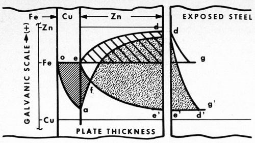
Figure 2 - Potential curves vs thickness of zinc plate, showing cathodic protection of steel with and without a copper strike. To the right, the different distances to which bare steel is protected from rusting are shown (bg and e'g').
The unplated steel is also cathodically protected (shown separately to the extreme right) by the curve dg along which the potential gradually falls off to that of the original steel (point g). Beyond g rusting occurs, but between the points b and g the bare steel is protected.
In the case of the panel with a copper strike, however, the potential of the surface first drops off closer to that of the more noble copper layer (curve oa). The steel in this area is anodic to the copper. At a, zinc plate is applied, and now the surface again gradually assumes the anodic potential of zinc (curve ad'). Copper in this instance becomes the cathode. The steel, buried under the copper plate, becomes part of the copper cathode.
The initial potential of steel at e now falls to the more cathodic value e'. Thus, the galvanic potential is increased from bd in the first case, to e'd in the second. Similarly, the cathodic protection of bare steel is also increased, this time by the distance e'g'.
Within the area oafe, the steel is anodic and pinhole rusting is pronounced. In contrast, within the area f'd', cathodic protection is obtained, and no rusting at all is evident. At point f, the potential of the corrosion cell is zero, the point of reversal of polarity. To the left the basis metal is anodic, to the right cathodic. As determined by the type of corrosion failure, reversal occurs in the salt spray and on outdoor exposure at a thickness of about 0.1 mil of zinc plate.
In the diagram it is also interesting to note that, as the thickness of zinc decreases by weathering away, the potential slowly drops off from the initial accelerated anodic value e'd' to one more and more restricted, as the zero point f is approached. As the driving force decreases, the rate of corrosion also decreases, and at the point f it all but stops.
The retardation has a balancing effect on thickness in that the thicker areas with more driving force carry relatively more of the corrosion current, and as a result tend to even up the plate. When failure does occur, it is quite general and surprisingly uniform.
Because of the above retardation, the overall protection is appreciably increased over that of zinc alone. Also, as a fallout, the copper strike reduces hydrogen embrittlement, and difficult cast irons are more readily covered with zinc.
Cadmium is similar in behavior to zinc except that sometimes its anodic potential is hardly sufficient to give cathodic protection to steel. For example, in the industrial atmosphere of Detroit, passivation has tended to lower the potential below the required value. As a result, pinhole rusting generally occurs instead of the typical anodic-patchy type.
Here again (as with zinc) a copper strike increases the cell potential, but in this case makes the difference between borderline failure and effective protection. Pinhole rusting does not occur as long as the thickness is more than 0.15 mil of cadmium, the reversal point. Greater thicknesses give progressively higher ratings than cadmium alone.
In both of the above cases the anodic character of zinc, and generally also of cadmium, is sufficient to give cathodic protection to steel, even without the assistance of a cathodic metal, such as copper. However, to bring out the full significance of the mechanism involved here, let us now examine the case of lead.
The mechanism in this instance is still the same, the only difference being that in the galvanic series lead is a step more cathodic than cadmium, and even slightly cathodic to steel. That is, both lead and copper are cathodic to steel, and separately each promotes pinhole rusting of the latter. However, when copper is applied, only a thin strike (0.015 mil) under the lead essentially eliminates pinhole rusting6 in thicknesses greater than 0.25 mil of lead.
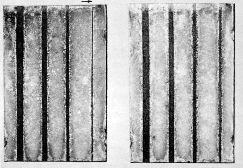
Figure 3 - Two steel panels plated with 1.0 mil lead, grooved after plating in widths 0.25, 0.1875, 0.125, 0.0625 in. to expose the steel. The left panel has a copper strike; the other, none. Outdoor exposure: ten years.
Significantly, exposure in the unpolluted atmosphere of State College, Pa., produced no rusting even in grooves of bare steel provided on some of the panels. Figure 3 shows a typical result after ten years' exposure. The two panels both have 1.0 mil lead, the one on the left with a copper strike, the other without. For several years, no rusting (with copper) was apparent even in grooves 0.125 in. wide. However, after ten years of exposure, erosion of the plate has progressed to the point where only the narrowest groove 0.0625 in. in the above figure is still rust-free.
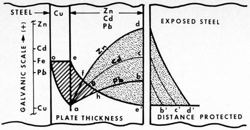
Figure 4 - Cathodic protection of steel. Potential curves are compared vs. thickness of zinc, cadmium and lead (plated over a copper strike). Separated to the right, the different cell potentials protect steel (rust-free) to the different distances indicated.
What does this mean? Let us examine Fig. 4. The relative potentials of zinc, cadmium and lead, assisted by a copper strike, are compared vs. thickness of plate. The curves are quite similar, differing only in galvanic potential. As indicated by the reference scale, cadmium is cathodic to zinc, and lead cathodic to cadmium.
In the case of lead, however, of particular interest is the fact that, in addition, lead happens also to be cathodic to steel. The small difference, however, can still be reversed by the copper strike, inasmuch as copper is cathodic to all three metals. That is, the copper undercoating is not only able to straighten out the borderline situation of cadmium (described above), but it is also sufficiently cathodic (in this intermediary role) to enable lead to protect steel cathodically.
As the diagram illustrates, the three cases differ in degree only, not in substance. The significant point demonstrated here can be summed up by the following statement:
A metal article can be cathodically protected by two other metal coatings though neither is anodic to it, provided that the more cathodic one is applied first, and sufficient thickness of the second is added to reverse the polarity of the article.
Now, to go a step further, if the mechanism described above is correct in satisfactorily explaining the beneficial combinations cited, then, to be complete, it should also be capable of predicting correctly the undesirable combinations. It follows, therefore, that the reverse extreme should yield a combination which, in contrast, should be to the same degree bad.
Stated concisely, a metal article can fail to be protected cathodically by two other plated metals, even when both are anodic to it singly, provided that the more anodic one is applied first, and the second one is plated in sufficient thickness to reverse the polarity.
Such an example is steel-zinc-cadmium. Platers have often attempted to improve the borderline corrosion resistance of cadmium by mistakenly thinking that a strike of more anodic zinc under the cadmium would be beneficial. Though such an approach does not seem unreasonable, nevertheless the combination does give unexpectedly bad results.
For example, in the ordinary salt spray 0.05 mil of zinc under 0.2 mil of cadmium showed white pinhole corrosion spots in 7 hr, while in 24 hr considerable undermining was evident; and at 72 hr heavy rust developed.
On the other hand, the reverse combination (0.2 mil Cd, 0.05 mil Zn) under the same conditions showed only general surface corrosion (no rust) during the entire 72 hr. The result was even superior to corresponding thicknesses of either metal alone.
A similar bad combination (steel-zinc-nickel) was reported many years ago by Blum, Strausser and Brenner.7 These authors stated, "During the first few months of exposure, white spots appeared over the surface, and a few months later decided rust appeared. It appears, therefore, that nickel accelerated, not only the corrosion of exposed zinc, but also of iron that was exposed when the zinc was penetrated, even though some zinc was still adjacent to the iron."
Now, to return to the zinc strike under cadmium, since cadmium is cathodic to zinc, applying the more anodic zinc first gives a combination just the reverse of that illustrated in Fig. 2. That is, the steel base becomes part of the zinc anode, and the more cathodic cadmium now promotes pinhole corrosion, first as white corrosion products of the zinc, and later as rust pits in the steel.
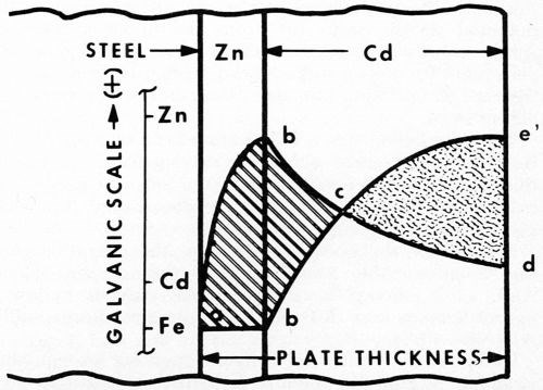
Figure 5 - Electrode potentials vs. thickness. This shows unfavorable coupling of Fe-Zn-Cd and failure to achieve cathodic protection, even though each metal alone is sufficiently anodic.
The reason for this behavior is apparent from the diagram of Fig. 5. The initial zinc strike (as before) by itself gives typical cathodic protection (curve ab). However, as soon as the more cathodic cadmium is applied, the surface rapidly becomes cathodic to the zinc (curve bed). The steel, covered by the zinc strike, soon reverses polarity (point c) and becomes part of the zinc anode (curve ece'). Thus, from point c on, the corrosion cell is determined by the Cd-Zn couple. Reversal takes place at about 0.1 mil of cadmium.
Pitting
As is well-known, pinhole corrosion (pitting) is associated with the anodic polarity of the article with respect to the outer plate. It is unsightly, and its extreme penetrating power makes it destructive as well. What makes it so powerful that, as Blum7 once pointed out, pits can penetrate into the steel, even when zinc is adjacent to it?
In the preceding diagrams, it was shown that reversal in polarity often overcomes the problem successfully. However, I should like to add here another observation that may be pertinent. It came to light many years ago during a patent search in regard to Electrocolor.
One of the references related to an ingenious experiment carried out 100 years ago (in 1870) by Wernicke,8 a German physicist, studying interference color phenomena. He was aware of the possibility of plating cuprous oxide from an alkaline copper tartrate solution, but his equipment was limited essentially to a Bunsen cell (1.84 V). The experiment is all the more remarkable when one begins to realize that this took place long before the electronics era. No voltage regulating equipment existed, not even a motor generator set. The electron had not yet been discovered. The electric light was a laboratory curiosity, and the basic electrical industry was still to be developed.
With these extreme limitations, however, Wernicke set out to plate cuprous oxide on copper, and did so with surprising ingenuity, using only the simple tool available to him, the Bunsen cell. It is now known by modern techniques that the cathode potential of his plating solution, to give successful deposits, must be maintained close to 0.2 V.
How did he do it, starting with nine times this voltage? Quite ingeniously, by simply decreasing the size of the anode. He found that, when the anode area was reduced to 1 mm2 and the cathode increased to 1 dm2, excellent deposits were obtained. The ratio of cathode to anode was 10,000/1, a value today we strive hard to avoid. By this simple expedient, however, Wernicke was able to reduce the cathode potential to the workable level (0.2 V). The anode potential constituted most of the remainder (about 1.6 V).
This remarkable achievement in its own right, however, has a parallel in the corrosion cell. That is, in pinhole corrosion, the process also starts with a small anode, usually in a pore even smaller than the 1 mm2 used by Wernicke. Also, the cathode area is often much larger than 1 dm2. The ratio initially, thus no doubt, often exceeds the above value by many fold.
In any event, it is evident that most of the potential drop (>80%, indicated above) must be concentrated at the pore site. As a result, the driving force behind pitting likewise is substantially increased, and certainly is sufficient to overcome the small differences that generally exist between the cathode potentials of adjacent metals, such as zinc against steel, mentioned by Blum.
Microcracked and microporous chromium
The case of chromium-plated steel is a typical example of the type just described. The cathodic surface is large, and the strong driving force in the pores often produces severe rust pitting of the steel. However, much has been done in recent years to overcome this difficulty by using microcracked and microporous chromium.9,10 It is now generally recognized that breaking up the chromium cathode into small units materially reduces the penetration of corrosion.
From the analysis described in the previous section, it follows that when the anode and cathode sizes approach equality the concentration of anodic potential in the pores may drop back almost 50% (several tenths of a volt). This substantial reduction in driving force, when coupled with the much smaller cell capacity of the micro-cells, makes the corrosion current all but disappear.
Also, the edges of the microcracks, as determined by the Dubpernell acid Cu test,11 are more active (anodic) than the surface. Indeed, the polarity of the Fe-Ni-Cr corrosion cell may even be reversed. Pitting is generally absent, and after exposure microporous chromium often shows a slight smokiness or etched appearance, but no rusting. In addition, panels with gross cracks frequently develop wider and wider hair-line fissures. Such behavior suggests that the chromium in the cracks and pores is corroding away anodically, thus accounting for the pit-free, etched condition.
On a micro-scale this is precisely analogous to industrial porous chromium,12 where the gross crack pattern is deliberately etched out anodically in order to widen the cracks into channels that provide the oil-retaining quality of the deposit. Here also, the edges of the cracks are more active and etch out (corrode) preferentially to the passive surface plateaus. In any event, the improvement in corrosion protection of microporous chromium is quite remarkable compared to the conventional deposit.
The anodic role of chromium
Until recently, the active state of chromium (anodic) was almost absent. Only occasionally would one encounter dissolution of chromium under organic coatings exposed to the salt spray. However, this new role for chromium is beginning to be harnessed. That is, besides the possible anodic behavior described above in connection with microporosity, a wholly new field is emerging for chromium in the canning industry. In this new role, chromium is exhibiting a number of interesting properties that are quite unusual and different from those normally encountered.
For example, chromium is plated in the mill right on the steel strip at line speeds running from 1000 to 2000 ft/min.13 The total plating time is only about 0.3 sec. The thickness, of course, is extremely low (about 0.3 μ-in). The steel is only partially covered with chromium. The plating step is followed by a chromate treatment and a special organic coating. These treatments are similar to those that have been used over the years for tin plate.
The small amount of chromium used in this new application, surprisingly enough, is sufficient to prevent blackening of the steel by sulfur, just as tin does. An accelerated test consisting of immersion in an alkaline sodium sulfide solution is used to compare the effectiveness of the coating. Steel alone, similarly treated, turns black almost immediately, whereas the thin chromium plate prevents the formation of black iron sulfide for the duration of the test.
This stain-preventing steel sometimes referred to as "the poor man's stainless" is turning out to be tremendously important to the canning industry, where the more expensive tin is being replaced by chromium. No doubt it will find other applications as the various useful combinations become better known. Its possibilities in decorative plating are practically nil, but, as a base for paint to inhibit rusting, this high-speed, low-cost strip has considerable merit.
What is the mechanism of this unusual corrosion behavior? We saw earlier that chromium is generally cathodic in service. In this new role, however, the organic coating eliminates oxygen, and, like the example observed above in the salt spray, chromium tends to revert closer to its inherent anodic position. Also, being amphoteric in nature, the alkaline sulfide solution encourages it to dissolve. Iron is not affected by alkali and remains passivated by the chromate treatment. The chromium, in dissolving anodically, induces a cathodic potential on the passivated steel. Thus, the repressed ferrous ion is not available to form the black iron sulfide. Such a mechanism is illustrated in Fig. 6 along with possible electrode reactions.
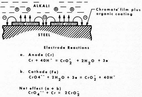
Figure 6 - Anodic behavior of chromium under an organic coating exposed to alkali.
A simple way to show the anodic behavior of an amphoteric metal in the presence of alkali is to insert a piece about an inch long part way into a test tube of silica gel containing a small amount of lead acetate (0.02M). Those metals anodic to lead in the galvanic (displacement) series become plated with lead from the gel. Large shiny crystals of lead form, such as illustrated in Fig. 7. The rate of formation and the crystal pattern vary with the driving power of the electrode potential. Thus, zinc, manganese, cadmium, thallium, iron and tin all give rather characteristic crystal patterns.
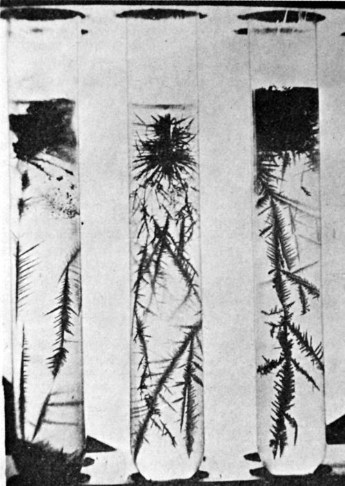
Figure 7 - Growth of lead crystals. Reducing metal (left to right): tin, cadmium, iron. Concentration of lead acetate: 0.1N; Age: 3 to 5 weeks.
Metals more noble than lead, however, show no deposit unless an anodic environment is provided on the protruding part of the inserted metal. For example, amphoteric metals such as lead or passive chromium can be made anodic by adding alkali on top of the gel. In this case, the top of the metal insert becomes anodic, and the bottom cathodic. Thus, in atypical fashion, lead plates out on lead or on chromium, as the case may be.
One can even reverse the polarity of such noble metals as silver and copper, simply by replacing the alkali with cyanide. Thus, instead of silver or copper plating out by immersion on lead (as is usually the case), the reverse process results, i.e., lead plating out on silver and copper.
Conclusions
From the foregoing discussion one is tempted to make a few projections that appear to merit further consideration.
We saw, for example, the good effect of a copper strike under zinc, cadmium and lead. Similarly, tin should be added to this group because of the increased interest in bright tin plating, and the need for a white metal substitute for the dwindling silver supply.
Particularly bad results on steel were noted when a zinc strike under cadmium or nickel was used. This deleterious effect also carries over to aluminum, as observed by Seyb, Jongkind and Gowman,14 who reported that zinc under tin plate was much inferior, to a bronze strike for the same purpose.
From the foregoing analysis the guiding principle that results is that the top two metals determine the initial polarity of the corrosion cell and generally of the article as well. Pitting can thus be prevented if the outside metal is anodic (or nearly so).
For a long time, it did not appear possible to eliminate pitting of chromium plate (steel-Cu-Ni-Cr), since passive chromium can go right to the cathodic limit of the galvanic scale. A silver strike was tried over the copper in an effort to reverse the polarity of the chromium; though improved results were obtained, pitting still persisted. Now, with microporosity, the more active chromium in the cracks and pores finally makes reversal possible. With the edges either slightly anodic, or close to it, the cell potential is markedly reduced, and pitting may be overcome altogether.
No doubt further improvements can still be made by refining and coordinating the electrode potential of chromium with respect to thickness and type of bath, as well as with the type of nickel adjacent to it.
The bipolar system of duplex nickel15 has added a major step forward in bright nickel and chromium plating. However, in addition to sulfur in the top layer, other considerations such as active alloying constituents and internal stresses are also known to make nickel more sacrificial. Further study in these directions should prove fruitful. For example, during the recent nickel shortage some composite systems on steel with as little as 0.03 mil of nickel were found to be superior in corrosion resistance to 1.5 mil of duplex nickel, using the following sequence of plate (mil): 1.5 bright acid Cu; 0.01 semi-bright Ni; 0.01 bright Ni; 0.01 high stress Ni; 0.01 microporous Cr.
Equally important is the cathodic potential of the semi-bright nickel; for, as long as this layer is kept in its more noble position, the mechanism remains intact, regardless of whether the top layer contains sulfur.
One final thought might be suggested as a guide in arriving at suitable composite metal coating systems. That is, it is more important to consider the feasibility of picking components so that the outermost metal is anodic, or nearly so, to the metal adjacent to it, than to be stymied by the realization that a particular cathodic metal, when plated alone on a basis metal (such as steel), might by itself be deleterious. In a composite coating system, it is quite likely to be beneficial instead.
References
1. N.E. Tomashov, R.M. Altovskv and G.P. Chernova, J. Electrochem. Soc., 108, 113 (1961).
2. R.D. Bedi, Plating, 55, 238 (1968).
3. A.T. Steer, J. Electrodepositors Tech. Soc., 25, 125 (1950).
4. H. Spahn, Trans. Inst. Metal Finishing, 42, 364 (1964).
5. B. Henze, First International Conference on Metal Corrosion, London. April, 1962; p. 394.
6. Am. Soc. Testing Mater. Proc., 53, 256 (1953); 55, B151, 338 (1955).
7. W. Blum, P.W.C. Strausser and A. Brenner, J. Res. Nat. Bur. Std., 13, RP712 (1932).
8. W. Wernicke, Pogg. Ann., 139, 132 (1870).
9. E.J. Seyb, Proc. Am. Electroplaters Soc., 50, 175 (1963).
10. H. Brown, Plating, 55, 1047 (1968).
11. E.M. Baker and W.L. Pinner, S.A.E. Journal, 22, 331 (1928).
12. T.G. Coyle, Proc. Am. Electroplaters Soc., 32, 20 (1944).
13. E.J. Seyb, R.E. Woehrle and F.G. Xeitzel, U.S. Patent 3,498,892 (1970).
14. E.J. Seyb, J. Jongkind and L. Gowman, Proc. Am. Electroplaters Soc., 51, 133 (1964).
15. A.H. DuRose, Plating, 57, 798 (1970).
About the author

Related Content
Successful South African Plater Beating the Odds
Remaining focused on quality and reliability, Team Plating Works stays profitable in a volatile and challenging economy.
Read MoreTrivalent Chrome Overview
As the finishing industry begins to move away from the use of hexavalent chromium to trivalent chromium, what factors should finishers consider as they make new investments? Mark Schario, chief technology officer for Columbia Chemical offers a helpful overview of this complicated topic.
Read More3 Tests to Ensure Parts are Clean Prior to Plating
Making sure that all of the pre-processing fluids are removed prior to plating is not as simple as it seems. Rich Held of Haviland Products outlines three tests that can help verify that your parts are clean.
Read MoreNanotechnology Start-up Develops Gold Plating Replacement
Ag-Nano System LLC introduces a new method of electroplating based on golden silver nanoparticles aimed at replacing gold plating used in electrical circuits.
Read MoreRead Next
Delivering Increased Benefits to Greenhouse Films
Baystar's Borstar technology is helping customers deliver better, more reliable production methods to greenhouse agriculture.
Read MoreEducation Bringing Cleaning to Machining
Debuting new speakers and cleaning technology content during this half-day workshop co-located with IMTS 2024.
Read MoreA ‘Clean’ Agenda Offers Unique Presentations in Chicago
The 2024 Parts Cleaning Conference, co-located with the International Manufacturing Technology Show, includes presentations by several speakers who are new to the conference and topics that have not been covered in past editions of this event.
Read More





.jpg;maxWidth=300;quality=90)
